


|
arduino IDEArduino
|
|

|
PrusaslicerPrusa
|
JP eCatFeeder
Overview
In 2017 I published the first iteration of this project. And since then, the cat feeder had been daily working. The mechanics is still the same and has proven its reliability over years.
Software has changed, starting using AI (a failure at that time), then using an old smartphone as a webcam. And now using a much more compact and cheap solution !
Here is what it looked like in 2017:
Sadly, Chicha (my cat in the video) died last year and won't be there for another video today...
Lessons learnt
Here are the lessons learnt during 8 years of daily operations:
- Ants love cat kiddles... When dish is on the floor, the day after it will be full of ants. So the dish must "float" in the air
- Cat is a hunter, he always prefer squirrels or birds or mouses to kiddles. If you feed it with the same amount of food, the day after the dish will overflow (and feed the ants !)
- kibbles are like a "3d tetris game" they tend to fall and intricate and block the feeder. A reliable anti jam feature is mandatory
- high capacity feeders are a must to take one month vacation for instance... But detecting that the feeder is empty is also needed
- notification that your cat is eating is fun but should occur only when your cat is eating and not when somebody is in front of the dish !
- Seeing your cat eating is a smart feature, not really mandatory but so fun !
We will see how these concerns have been addressed.
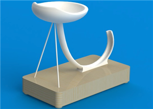
Mechanical design
Mechanical design is based on a pyramidal hopper which is dropping the kiddles on a big worm screw.
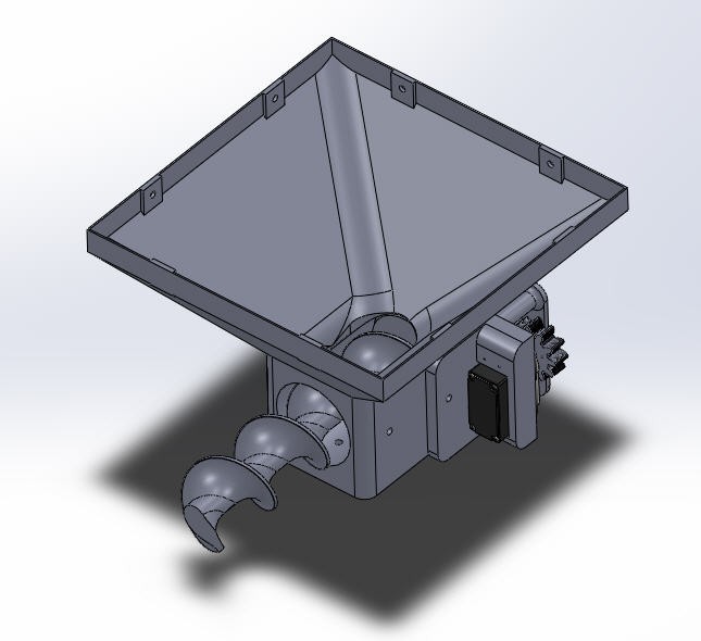
The worm screw is driven by a 360° RC servo and two gears.
 A 360° servo allows a continuous rotation in both direction CW or CCW. The PWM signal only allow to control rotation direction and speed (not position).
T

Anti jamming :
to prevent blocking the worm gear, motion is controlled in both directions by software. This will "shake" the kibbles and help them drop from the hopper into the worm gear.
To avoid blocking the worm gear in "forward motion" a rubber lip is glued into the hopper on the its front side. This soft lip will absorb all the constraints and, toghether with the back and forth motion, prevent any jamming. Trust me it works !

As you can see on this picture a PVC pipe is inserted around the worm gear and a slot is cut on top of it to allow kibbles to drop into the worm gear.
PVC is perfect to allow a friction less motion into the pipe. It is strong, very soft and naturally shiny (almost "oiled").
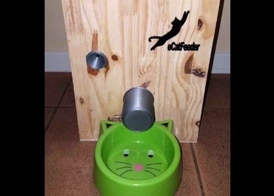
Weighing the dish
Weighing the dish is an idea which fixes a lot of concerns explained above!
- the dish will "float" above the ground preventing ants to eat the kibbles
- when the cat is eating, weight of the dish decreases. It's an elegant way to detect "cat eating" event
- when the kibbles are dropping we can measure the exact ration we want to deliver to the cat and stop worm screw motion
- if the dish is not empty, we only fill it to the exact ration, preventing "overflow"
- if the kibbles do not fall it is either a jam situation or an empty hopper one. A notification can be sent to your smartphone
So a load cell is added under the hopper it acts as a kitchen scale !

Outer walls assembly
Finally, as shown on the picture, wooden walls are added around the hopper. They are fixed together using 3d printed feets and 5mm wood screws. Dimensions to cut the 18mm plywood are given into the 3d printed parts package.
Here is an exploded view: Assembly of all these parts is fairly easy and straightforward
 As you can see holes are drilled into the front wall to accommodate the camera and the motion detector (IR sensor).
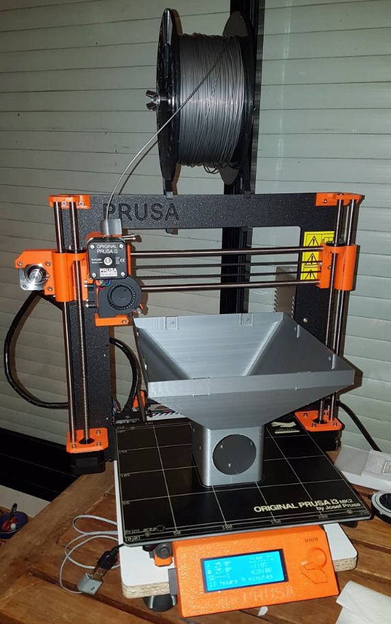
Printing the catfeeder
Most of the parts are printed with PLA filament. All the files are downloadable on my "printables" project page
The biggest one is the hopper ! It can however be printed directly on my Prusa i3 Mk2.s printer without any support.
The auger must be as strong as possible and as smooth as possible. For these reasons, it is printed with ABS filament.
To keep it stronger and to avoid supports, the auger is printed cut into two halves horizontally. Then it is glued with acetone. And it is also smoothed with acetone (see here how to do it).

When all this is done, your catFeeder is almost finished... Well still missing some electronic stuff !
Electronics
Schematics

Micro controller
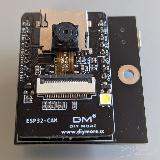
The heart of the system is an Ai-Thinker ESP32-CAM microcontroller. It is a cheap but powerful dual cores 32 bits microcontroller that you can program easily with Arduino IDE
This MCU has a tiny 2xMPixels camera OV2640 which will be perfect to monitor our cat !

A few IO pins are available for DIY projects.
I have used most of them !
- IO12 and IO13 to control the Load cell driver HX711
- IO15 to control the RC servo
- IO12 to get the PIR sensor signal
- IO11 , IO14 and IO15 to flash the fimware
sensors used
360° servo :
A 360° servo allows a continuous rotation in both direction CW or CCW. The PWM signal only allows to control rotation direction and speed (not position).
These servos are easy to source : Servo at aliexpress
Their dimensions are standard : 40.8*20.2*28.5mm
A model with metal gears and a torque > 10kg.cm is needed. The worm gear can apply a lot of strength to the kibbles when jamming occurs...
PIR sensor
The MCU will sleep most of the time saving energy.
It will be waken up by an infra red sensor via an interruption signal.
The model I have choosen is the cheapest one : HC-SR501

The white radom can be removed, so that the sensor will fit into the 3D printed part and look at the cat from inside the front wall.
Whenever something passes in front of the feeder, the output of the PIR sensor will go "high" and wake up the ESP32.
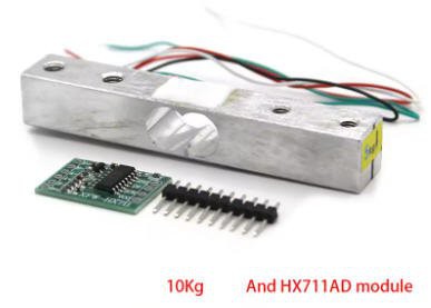
LoadCell
The loadcell will measure the weight of the food.
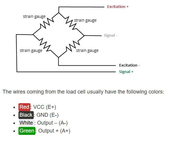
I have choosen a 1kg loadcell. This device need an amplifier HX711 to adapt its value.
Connection between load cell and amplifier follows this schematics:
Programming the ESP32-CAM
Unfortunately this MCU is not equiped with an on board USB to Serial adapter. We will need to use an external one to program our catFeeder.
A lot of solutions does exist. I have choosen this one : CP2102 FTDI USB to TTL

We will see later on how to use it.
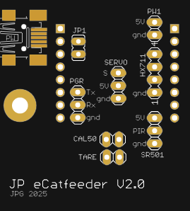
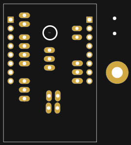
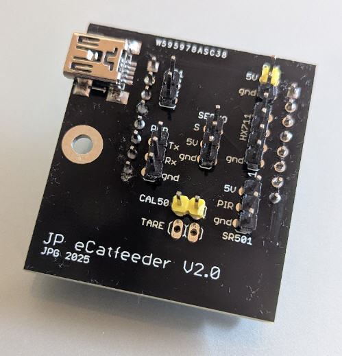
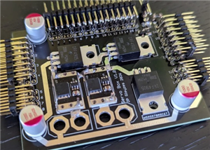
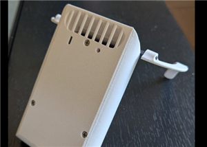
PCB
I have designed a nice and compact PCB allowing to fit the ESP32 and to connect all the sensors
The PCB was kindly sponsored by PCBWay and is as usual of excellent quality.

You can order it directly from this page. It's cheap, delivered very fast and so professional looking!
And if you are new to PCBWay please use this affiliated link : https://pcbway.com/g/o35z4O

This PCB exposes all the native connectors for the various modules used. It's very very easy to solder !
Power considerations
The board uses 5V DC power supplys for the ESP32 and all the sensors. The servo is also powered at 5V and can eat 1 or more Amps of current. So you can power the system with a smartphone charger, provided it can deliver more than 1A. (2A is a perfect choice).
You can plug the 5V directly on the USB connector (PW) or on the pin headers (PW1) of the PCB.
Software : ESP32 firmware
Firmware for the catFeeder is available on my Github pages
You will find there everything needed to compile and configure your catfeeder.
Arduino installation
You will need to install Aduino IDE : https://www.arduino.cc/en/software
Then you should add a reference to your ESP32 board. Simply open preferences and add this link to the "Additionnal Boards Manager URLs" : https://espressif.github.io/arduino-esp32/package_esp32_index.json

Then you should see your ESP32 board into the board Manager menu

Libraires installation
You will need to install a few libraries before compiling your CatFeeder... Most of them are installed via the Libraries Manager.
Ticker

WifiManager to configure your Wifi Credentials

Time for NTP time synchro

URLencode for WhatsAppNotification

All this being done you should be able to compile your Weather Station without error !
Unzip the github project and open it into the IDE
You should see 5 opened files

I have only modified the .ino one. All the 4 other are original files from the AI-thinker repo. They might be "old" versions but they do work with my board !
You can try to compile it should work but we have to jump into the source code for some parameters changes
And I still have to explain how to flash the firmware...
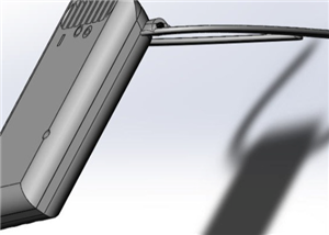
Flashing the firmware
connect your USB to serial dongle to your cat feeder. Don't forget to bridge the jumper JP1. This will force GIO0 to ground and allow the ESP32 to boot into bootloader mode.

Do not connect the 5V nor the +3.3V on the dongle (but of course plug it into your PC USB port !). Instead plug the +5V on your board and now click on the compile button. A few second after, the firmware will be uploaded.
Remove the jumper on JP1 and reset the ESP32 (or disconnect/reconnect the +5V). Your catfeeder will boot !
configuring the wifi
To configure the wifi simply follow this procedure:
I have used the ESP32 WifiManager library capabilities to enter wifi credentials on the ESP32 board.
So if you boot the board (or reset it with the reset button) while touching the "CAL50" touchpad on the PCB d, then the ESP32 exposes a Wifi hotspot (named "JP eCatfeeder" on which you can connect any smartphone (or PC)
Connecting to it will automatically open a configuration window

Click on the "Configure Wifi" button to choose an exisitng wifi network for which you have the credentials and enter them !
Your ESP32 board is now configured to run with wifi and you would want to monitor your cat and receive notifications !
WhatsApp notifications
Your cat can send you whatsApp notifications !
It's easy... I used the CallMeBot service to send text notifications to my phone.
Go to the callMeBot page and follow the instructions using whatsApp on your phone

And you will receive a message with your ApiKey inside.

Once you have allowed CallMeBot to send you notifications, then you have to configure your phone number and your APIkey into the source code (line 145)
//WhatsApp callmebot : https://www.callmebot.com/blog/free-api-whatsapp-messages/ // +international_country_code + phone number // France +33, example: +36010100101 String phoneNumber = "+YOUR_PHONE"; String apiKey = "YOUR_APIkey";
Now you can compile again your code and you should be able to receive messages from your cat !
Calibration of the daily ration
As any scale your catFeeder must be calibrated:
- the tare should be done with an empty plate on the scale. So, run the catfeeder, let it boot and before it goes to deepsleep (40s) touch the CAL50 touchpad on the PCB during 4s (more than 3s and less than 6s). That's as simple as this !
- the daily ration should be calibrated after the tare is done. drop the kibbles you want into the plate, run the cat feeder, let it boot and press the "CAL50" touchpad on the PCB during 7s. (more than 6s)
For each of these actions , you will receive a notification to acknowledge the calibrations
Feed hours are fixed into the code, but you can change them easily (line 255/256)
FeedHour1 = preferences.getInt("FeedHour1", 7); FeedHour2 = preferences.getInt("FeedHour2", 20);
I do feed my cat at 7 in the morning and 20 in the evening !
You may also notice that I calibrated my feeder with 50g ration. But as the weight is never displayed, you can put the ration you want, calibration will work as well even when saying that 80g is 50g :-)
Seeing your cat when he eats
If you are here, into this long description, then you want to be rewarded and see your cat eating.
How does it work ?
1) PIR sensor detects something and boots your ESP32
This is done by 2 lines of code !
you define a bitmask for your GPIO :
#define PIR_PIN_BITMASK 0x4 // 2^2 (exponent is GPIO number) in hex
and you enable external interupts to wake up the ESP32 from deepsleep when this GPIO goes "high"
esp_sleep_enable_ext1_wakeup(PIR_PIN_BITMASK, ESP_EXT1_WAKEUP_ANY_HIGH); //this will be the code to enter deep sleep and wakeup with pin GPIO2 high
2) ESP32 is now booted and enters the setup routine
3) Thus you weight the plate just after boot time into the setup routine
AverageWeight = GetRawWeight(); AverageWeight = CalibZero - AverageWeight; AverageWeight = AverageWeight * 50.0 / Calib; RealTimeWeight = AverageWeight;
4) you do the same thing repetitively inside the loop routine
And if you detect a variation of weight, then your cat (or the neighbour's one!) is eating.
if ((abs(AverageWeight - RealTimeWeight) > 10.0) && (SendEating == true)) // if weight has changed more than 10g then cat is eating { SendAlarm = true; Mess = "Cat is eating. Live stream here \n\"http://"; Mess += IpAddress2String(WiFi.localIP()); Mess += ":81/stream\""; SendEating = false; // clear the flag to only send one notification ! } RealTimeWeight = AverageWeight; // and update the real time weight
Then the catFeeder will send a notification (only once)

5) And if you follow the URL you will have access to the live stream of your cat :

As I said Chicha my cat is dead so I filmed the first picture I found on internet (and blurrred it a little to avoid copyright issues !)... Sorry Joseph !
6) Finally, at the end of the loop, ESP32 will go into deepsleep if you are not connected to the livestream (50s timeout) and if nothing is moving in front of the PIR sensor
if ((millis() - Timeout) > 50000) //if more than 40s without connection then sleep { #if defined DEBUG_OUT Serial.println("Time out connection --> stop now"); #endif doStop = 1; //force stop } if ((doStop == 1) && (digitalRead(PIR_PIN) == LOW)) { #if defined DEBUG_OUT Serial.println("Going to sleep now"); delay(200); #endif esp_deep_sleep_start(); //enter deeep sleep mode if PIR sensor is off and time out }
JP eCatFeeder
*PCBWay community is a sharing platform. We are not responsible for any design issues and parameter issues (board thickness, surface finish, etc.) you choose.


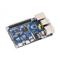


Raspberry Pi 5 7 Inch Touch Screen IPS 1024x600 HD LCD HDMI-compatible Display for RPI 4B 3B+ OPI 5 AIDA64 PC Secondary Screen(Without Speaker)
BUY NOW


- Comments(0)
- Likes(1)
More by Jean-Pierre Gleyzes
-
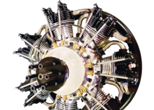
 RC radial engine spark plug heater
BackgroundMy friend bought this wonderful engine from UMS_technologiesIt's a 7 cylinders star engine...
RC radial engine spark plug heater
BackgroundMy friend bought this wonderful engine from UMS_technologiesIt's a 7 cylinders star engine...
-
 Convert a DC motor into a stepper one
This project is a way to convert a DC motor into a stepper motor.Of course "conversion" will not be ...
Convert a DC motor into a stepper one
This project is a way to convert a DC motor into a stepper motor.Of course "conversion" will not be ...
-
 OpenxSensor variometer and telemetry for RC planes
Ever wanted a very cheap variometer on your RC glider ?battery voltage monitoring ?extra RC channels...
OpenxSensor variometer and telemetry for RC planes
Ever wanted a very cheap variometer on your RC glider ?battery voltage monitoring ?extra RC channels...
-
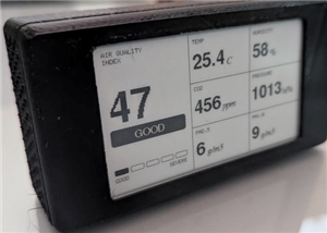 Air Quality station (e-paper and Home Assistant)
OverviewThis DIY air quality monitoring system integrates precision sensors with a connected process...
Air Quality station (e-paper and Home Assistant)
OverviewThis DIY air quality monitoring system integrates precision sensors with a connected process...
-
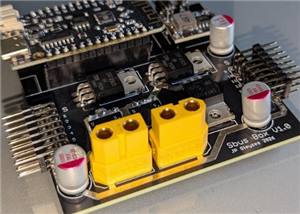 2S LiPo High-Current Power Box with two Sbus inputs
Project Overview: 2S LiPo High-Current Power Box with two Sbus inputsThis circuit is a high-performa...
2S LiPo High-Current Power Box with two Sbus inputs
Project Overview: 2S LiPo High-Current Power Box with two Sbus inputsThis circuit is a high-performa...
-
 Power box for big RC plane
Project Overview: 2S LiPo High-Current Power BoxThis circuit is a high-performance power distributio...
Power box for big RC plane
Project Overview: 2S LiPo High-Current Power BoxThis circuit is a high-performance power distributio...
-
 A bluetooth Joystick for TX16s radio (or others)
This project is kind of follow on of this one : Buddy Box for Radiomaster TX16sI decided to write an...
A bluetooth Joystick for TX16s radio (or others)
This project is kind of follow on of this one : Buddy Box for Radiomaster TX16sI decided to write an...
-
 Radiomaster TX16s buddy box (master/trainer and more)
I wanted a wireless buddy box for my Radiomaster TX16sThis buddy box would allow to wireless link tw...
Radiomaster TX16s buddy box (master/trainer and more)
I wanted a wireless buddy box for my Radiomaster TX16sThis buddy box would allow to wireless link tw...
-
 "perpetual" motion ball
Browsing internet and youtube, I found this mind blowing "perpetual motion" device designed by Willi...
"perpetual" motion ball
Browsing internet and youtube, I found this mind blowing "perpetual motion" device designed by Willi...
-
 Freon: Freeze On Neck - 3d printed box top
Freon project is fully describbed on this project page
Freon: Freeze On Neck - 3d printed box top
Freon project is fully describbed on this project page
-
 Freon: Freeze On Neck - 3d printed box bottom
Freon project is fully described on this project page
Freon: Freeze On Neck - 3d printed box bottom
Freon project is fully described on this project page
-
 Freon: Freeze On Neck personal cooler
DescriptionAre you tired of sweltering through hot days, feeling uncomfortable and unproductive?Imag...
Freon: Freeze On Neck personal cooler
DescriptionAre you tired of sweltering through hot days, feeling uncomfortable and unproductive?Imag...
-
 ESP32_StarMotor_glow plugs heater _ V2
BackgroundMy friend bought this wonderful engine from UMS_technologiesIt's a 7 cylinders star engine...
ESP32_StarMotor_glow plugs heater _ V2
BackgroundMy friend bought this wonderful engine from UMS_technologiesIt's a 7 cylinders star engine...
-
 RC plane CoG finder
IntroductionAs an intro here is a video of the system runningand another using the LCD displayA litt...
RC plane CoG finder
IntroductionAs an intro here is a video of the system runningand another using the LCD displayA litt...
-
 JP eCatFeeder
Overview In 2017 I published the first iteration of this project. And since then, the cat feeder had...
JP eCatFeeder
Overview In 2017 I published the first iteration of this project. And since then, the cat feeder had...
-
 ESP32_RC_Motor_tester_V2
FeaturesOn an RC plane, propeller performance depends on pitch, diameter, profile, and material.Test...
ESP32_RC_Motor_tester_V2
FeaturesOn an RC plane, propeller performance depends on pitch, diameter, profile, and material.Test...
-
 ESP32_RC_Motor_tester
FeaturesOn an RC plane, propeller performance depends on pitch, diameter, profile, and material.Test...
ESP32_RC_Motor_tester
FeaturesOn an RC plane, propeller performance depends on pitch, diameter, profile, and material.Test...
-
 FluidNC foam cutter controller
A few months ago I retrofited an old foam cutter based on a MM2001 hardware.This system works quite ...
FluidNC foam cutter controller
A few months ago I retrofited an old foam cutter based on a MM2001 hardware.This system works quite ...
-
Programmable Mist Maker - XIAO / QT PY Extension
553 1 0 -
RadioHAT - Raspberry Pi radio development platform
438 0 1 -
-
-
-
-
ARPS-2 – Arduino-Compatible Robot Project Shield for Arduino UNO
2950 0 6 -
A Compact Charging Breakout Board For Waveshare ESP32-C3
3463 3 8 -
AI-driven LoRa & LLM-enabled Kiosk & Food Delivery System
3806 2 2


