


ESP32_RC_Motor_tester
Features
On an RC plane, propeller performance depends on pitch, diameter, profile, and material.
Testing your propellers will allow you to measure and improve their efficiency.
This motor + propeller test equipment will measure:
- Thrust
- RPM
- Current
- Voltage
- Electrical power
- Temperature
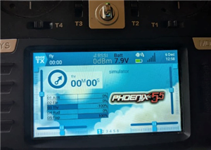
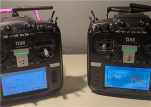
It can be controlled either manually via a servo tester or your radio transmitter/receiver or automatically via your Android phone.
Please note that the full project is available on my hackaday's pages
And here is a video showing the system running
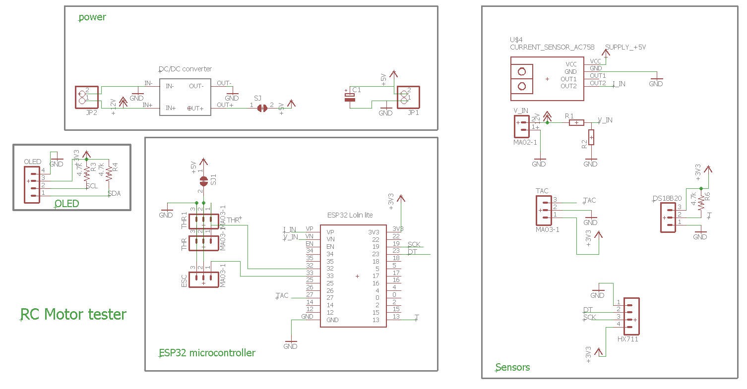
Schematics
The heart of the system is based on a Lolin32 lite ESP32 microcontroler.
Then a bunch of sensors are added to measure all the parameters.
An Oled dispaly is (optionnaly) there to help debug or usage without smartphone
Bill of material can be found at the bottom of this page
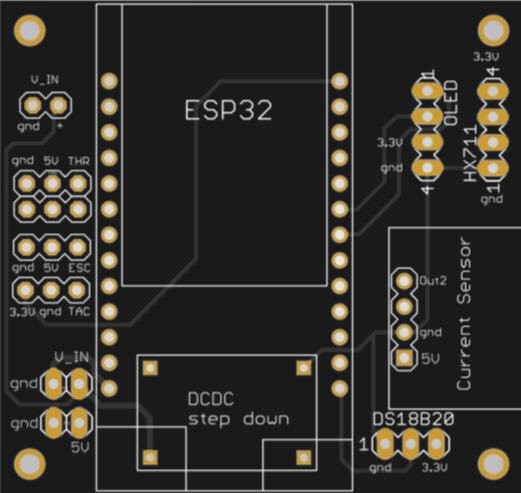
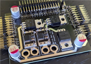
PCB
I have designed a nice and compact PCB allowing to fit the ESP32 an a connect all the sensors
The PCB was kindly sponsored by PCBWay and is as usual of excellent quality.

You can order it directly on this page !
And if you are new to PCBWay please use this affiliated link : https://pcbway.com/g/o35z4O
Power considerations
5V can be delivered either by the DC/DC converter (prefered solution) or directly by the ESC of your plane
power with DC/DC converter :
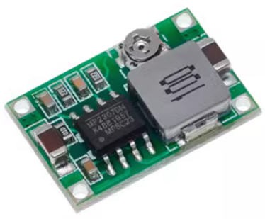
- first tune the trim pot value in order to get less than 5V (4.8V) output (do not power anything else before...)
- when this 5V is achieved, you can paint the trim pot with a drop of nail varnish to fix the potentiometer
- then (and only then) solder the SJ solder pad on the bottom side of the PCB. The 5V will now flow to the DFPlayer and the ESP32 (via the battery connector)
- Do not solder the SJ1 solder pad
using the DC/DC will insure a stable 5V supply which is used by the current sensor. Zero current is half the 5V supply. So this value ("5V") must be stable. If powered by the ESC, the "5V" could be as well 4.8V of 5.2V... this would induce a biais into the idle current measurement from ESC to ESC... So it's better to have a consistant "5V" which will allow to calibrate properly the current sensor.
Power with the ESC :
If your ESC is equiped with a strong enough BEC (1A for the ESP32) you can power the board and the ESP32 directly with the ESC connector :
- do not solder the SJ solder pad (nor the DCDC module if you want)
- solder the SJ1 solder pad
- connect the ESC servo pin header to the ESC connector on the board and power your ESC
I however do not recommand this second option (power with the ESC) as the 5V delivered by the ESC would change form ESC to ESC... see above...
Power with the USB plug :
It is safe but not reliable for exactly the same reason as above.
However you can power the device by the DC/DC converter (or the ESC) AND plug safely your USB to the PC for debugging purposes.
sensors
Five sensors are there to measure the parameters of your motor and propeller:
- ADC to measure battery voltage
- current sensor to measure current flowing into the motor
- IR sensor to measure rotation speed of the propeller
- temperature sensor to prevent over heating of the controller
- load cell sensor to measure the "weight" of the propeller (converted to thrust !)
Links for these sensors are provided into the bill of material
ADC
Voltage of the battery is directly measured by one of the ESP32 ADCs
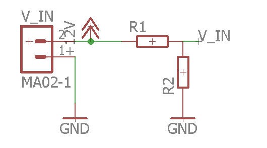
R1/R2 are a voltage divider needed to decrease the battery voltage to the ESP32 range (3V)
V_IN = R1 x Vbat / (R1 +R2)
So you have to be careful when selecting these resistors depending on the maximum voltage you plan to use for your battery.
Here are the values for a lipo 3s battery (my prefered setup!)
With R1 = 20k and R2 = 6.8k you will get max 3.3V with a fully charged lipo at 13V (3x 4.3V = 13V)
current sensor
To safely measure high current motors I have selected a powerful 100A current sensor : ACS758_100B
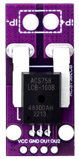
This sensor module is equiped with an operationnal amplifier on its OUT2 pin. So that you can input this pin safely on a micro controller ADC.
This sensor is "bidirectionnal" meaning that it can measure positive and negative currents. The zero value is at mid range of the ADC thus at 2.5V when the sensor is powered at 5V. This is totally within the range of the ESP32 ADC specifications. (no need to change this OUT2 value if you measure values between 0 and 2.5V !).
LoadCell
A loadcell will measure the thrust of the propeller.
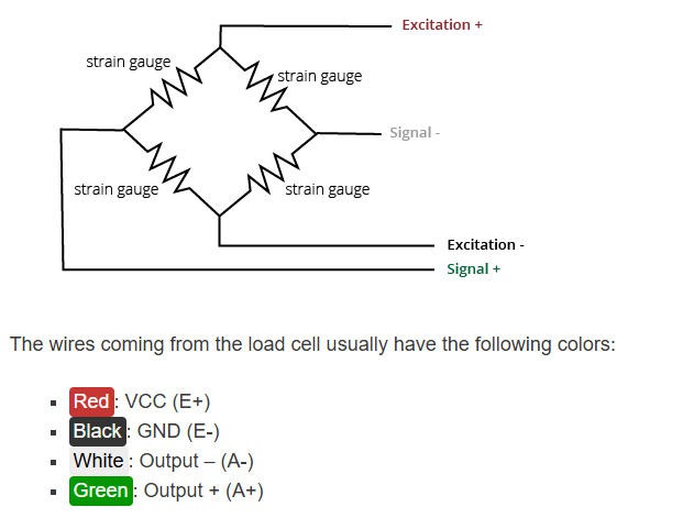
I have choosen a 10kg loadcell. This device need an amplifier HX711 to adapt its value.
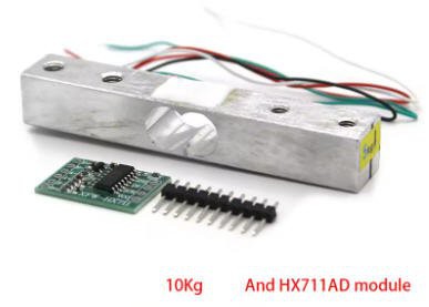
Connection between load cell and amplifier follows this schematics:
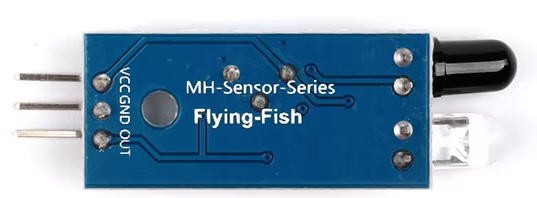
Propeller RPM
To measure the propeller speed we need to setup a tachometer. It will be made with an IR sensor. The reflection of the IR beam on the arms of the propeller will trigger interrupts on the ESP32, and we will compute the rotation speed.
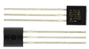
Temperature
A DS18B20 chip will take care of measuring the temperature of the ESC.
Basic wiring
Here is how the system should be connected to have a "basic" working condition:
- ESC is controlled by a servo tester
- current sensor is put in place between the ground and the negative side of the battery connector
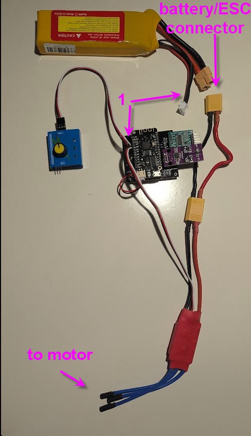
note that:
1) red wire of the balance plug of the battery should be connected to +V_in pin of the board
2) the load cell connector should be connected as well (not shown on the picture
3) the black wire from the ESC should go to IP- pin of the current sensor
4) IP+ pin of the current sensor shoud go to the negative wire of the battery pack
Software
ESP32 Firmware
Firmware is availble on my Github pages
This firmware needs to be as fast as possible for sensors acquisition. So all the sensors as acquired into the main loop and then sent to the Android application using UDP.
UDP is a "send and forget" protocol over IP. It is, by far, the fastest wireless protocol available to transfer data between computers.
So the firmware will take care of establishing the connection with the Android phone. This will be done automatically without having to enter any "manual handshake" by the user.
The only condition is that both the phone and the ESP32 are connected to your wifi router.
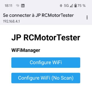
configuring the wifi
To configure the wifi simply follow this procedure:
I have used the ESP32 WifiManager library capabilities to enter wifi credentials on the ESP32 board.
So if you boot the board (or reset it with the reset button) while touching the "GPIO15" touchpad on the lower right corner of the board, then the ESP32 exposes a Wifi hotspot (named "JP RCMotorTester" on which you can connect any smartphone (or PC)
Connecting to it will automatically open a configuration window
You then have to choose an exisitng wifi network for which you have the credentials, enter them into the form
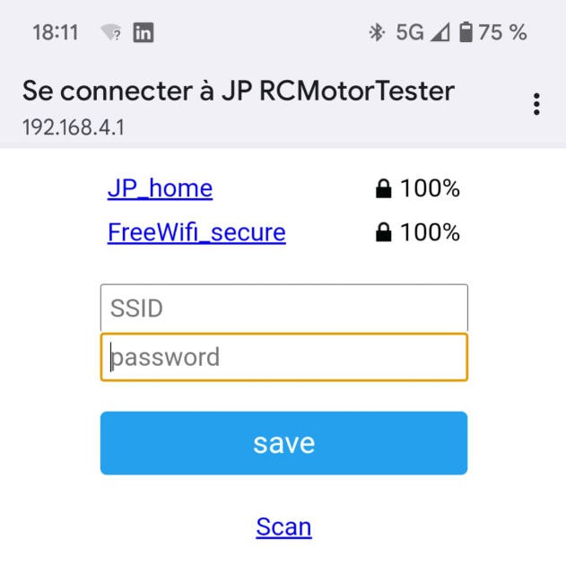
Your ESP32 board is now configured to run with wifi and you would be able to monitor your motor with the android App
Android Application
Android App is available on my Github pages
You can compile the source code using B4X freeware compiler or use directly the .apk file available into the github project.
When installing the App you will get warnings saying that this App is "old", go on installing it it is safe!
Using the App is very very simple:
- launch it
- look at the points arriving into the screen !
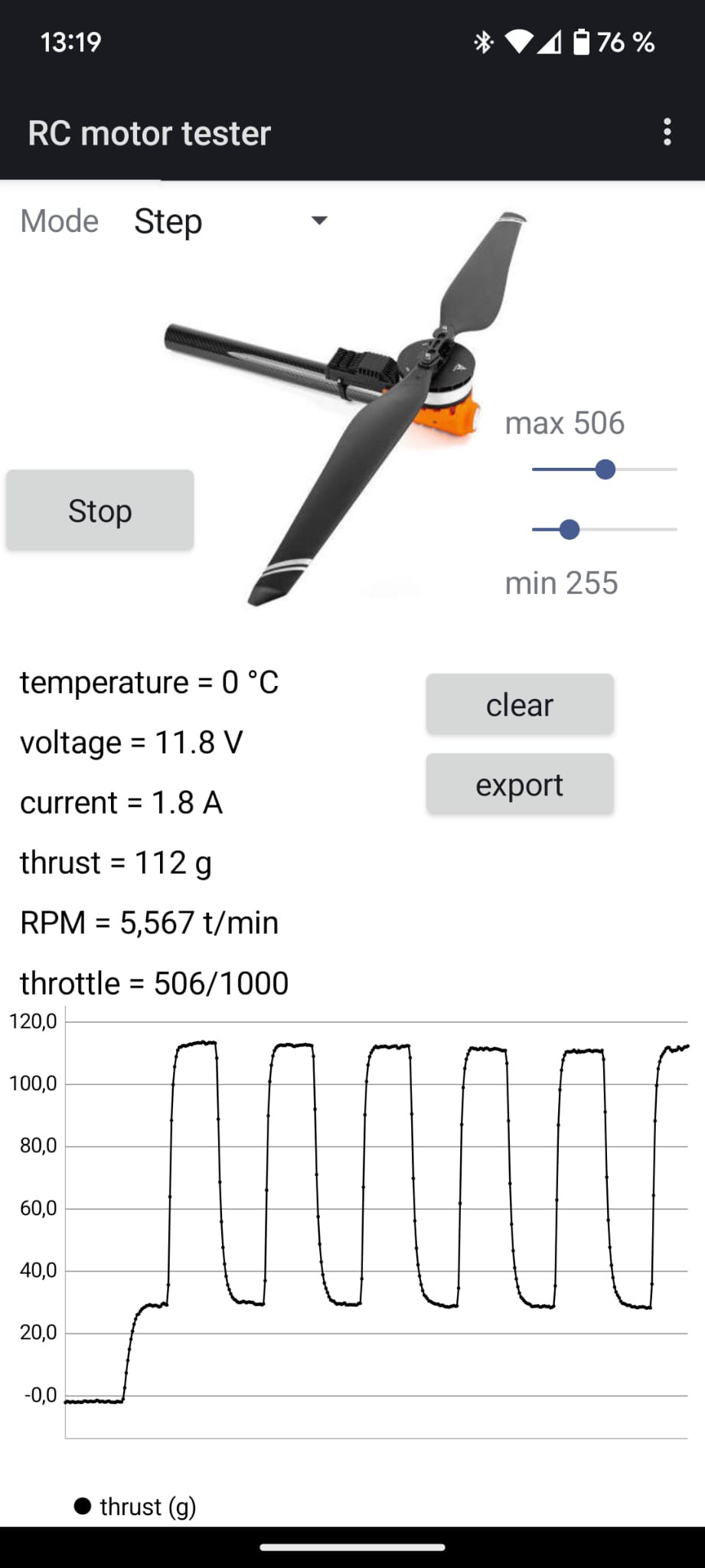
- click on the labels : temperature, voltage, ..., throttle to change the display
- click and zoom on the curve to analyse it
- click on the "clear button" to ... clear the curve
- click on the "export" button to export all the acquisition (even the oldest hidden part of the curves). The file will be saved into the "download" folder of your phone. It is a text file that you can import into excel.
change the mode of operation between:
- manual : throttle control is done either by your RC receiver or servo tester
- step : will perform steps between min and max throttle values
- sweep : will perform a saw teeth pattern between min and max
- stop : stops the motor
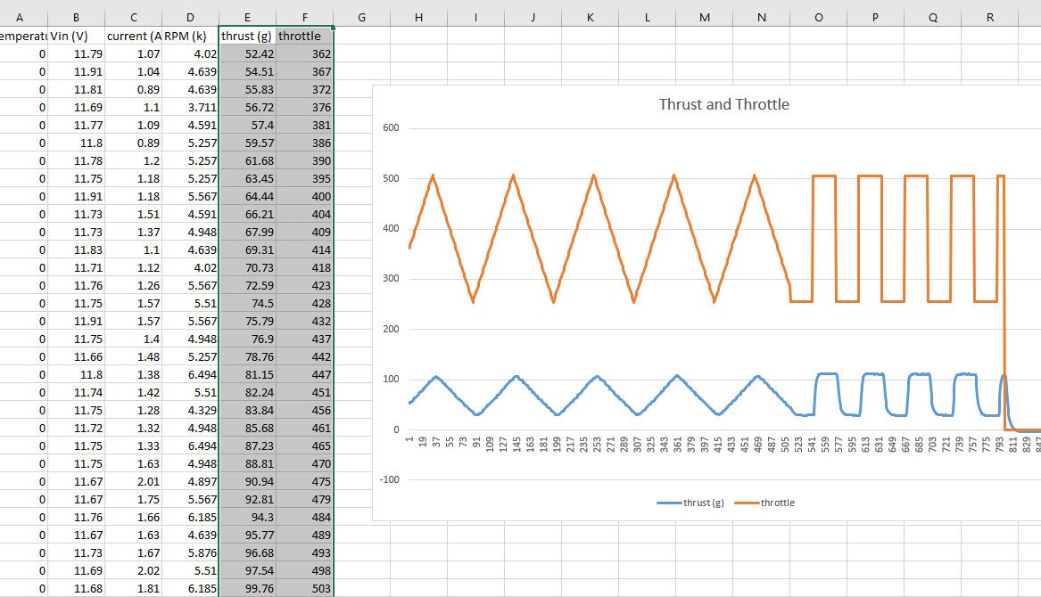
Here is another screenshot showing two successive acquisitions "sweep" followed by "step"

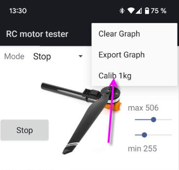
Finally, into the top right 3 dots menu you can access to the calibration of the load cell.
What you will have to do is to start the system (motor off) and the arm horizontal. Then (when some points arrive) attach a 1kg load to the spinner and launch the calibration (not the motor !)... That's it your load cell is calibrated and will keep this value.
During start up two other calibrations are performed :
- "tare" of the loadcell. This will "erase" the weights of the propeller and of the motor
- calibration of the zero current of the hall sensor
Due to these calibrations, which can last around 10s, do not start your motor before you see new points coming into the curves...
Excel export
Here is an example file when using the "export" button.
You can open this file into a spreadsheet and do what you want with the data !
troubleshooting :
If the acquisition of new points do not start, it likely to be a problem into the communication protocol.
Try these tricks:
- close the App (do not kill it) use right button or right to left swipe
- if it still do not work try to reboot your wifi router (I had to do it with my freebox...)
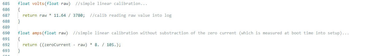
If the calibrations of current and voltage are not precise enough... plug an ampere meter and a volt meter into the battery, un comment the DEBUG_VIN and DEBUG_CURRENT lines and read the log file into your Arduino IDE...
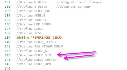
Then change the calibration values accordingly into the volts() and amps() functions, and recompile the ES32 firmware
ESP32_RC_Motor_tester
Project images are for reference only. Actual production is based on the manufacturing files on the project page.
Please review the designer's notes (e.g., PCB thickness) and select the appropriate options.
PCBWay is not responsible
for issues caused by unsuitable parameter selections.
For more important ordering information, please refer to
Read More


Raspberry Pi 5 7 Inch Touch Screen IPS 1024x600 HD LCD HDMI-compatible Display for RPI 4B 3B+ OPI 5 AIDA64 PC Secondary Screen(Without Speaker)
BUY NOW


- Comments(2)
- Likes(0)
More by Jean-Pierre Gleyzes
-
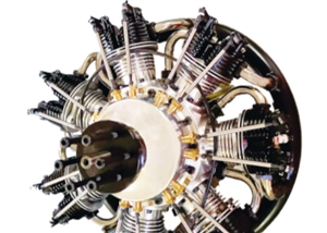
 RC radial engine spark plug heater
BackgroundMy friend bought this wonderful engine from UMS_technologiesIt's a 7 cylinders star engine...
RC radial engine spark plug heater
BackgroundMy friend bought this wonderful engine from UMS_technologiesIt's a 7 cylinders star engine...
-
 Convert a DC motor into a stepper one
This project is a way to convert a DC motor into a stepper motor.Of course "conversion" will not be ...
Convert a DC motor into a stepper one
This project is a way to convert a DC motor into a stepper motor.Of course "conversion" will not be ...
-
 OpenxSensor variometer and telemetry for RC planes
Ever wanted a very cheap variometer on your RC glider ?battery voltage monitoring ?extra RC channels...
OpenxSensor variometer and telemetry for RC planes
Ever wanted a very cheap variometer on your RC glider ?battery voltage monitoring ?extra RC channels...
-
 ESP32 Linky Teleinfo (TIC) to MQTT – Real-Time Home Assistant Integration
The teleinfo component allows you to retrieve data from a French electrical counter using Teleinform...
ESP32 Linky Teleinfo (TIC) to MQTT – Real-Time Home Assistant Integration
The teleinfo component allows you to retrieve data from a French electrical counter using Teleinform...
-
 Air Quality station (e-paper and Home Assistant)
OverviewThis DIY air quality monitoring system integrates precision sensors with a connected process...
Air Quality station (e-paper and Home Assistant)
OverviewThis DIY air quality monitoring system integrates precision sensors with a connected process...
-
 2S LiPo High-Current Power Box with two Sbus inputs
Project Overview: 2S LiPo High-Current Power Box with two Sbus inputsThis circuit is a high-performa...
2S LiPo High-Current Power Box with two Sbus inputs
Project Overview: 2S LiPo High-Current Power Box with two Sbus inputsThis circuit is a high-performa...
-
 Power box for big RC plane
Project Overview: 2S LiPo High-Current Power BoxThis circuit is a high-performance power distributio...
Power box for big RC plane
Project Overview: 2S LiPo High-Current Power BoxThis circuit is a high-performance power distributio...
-
 A bluetooth Joystick for TX16s radio (or others)
This project is kind of follow on of this one : Buddy Box for Radiomaster TX16sI decided to write an...
A bluetooth Joystick for TX16s radio (or others)
This project is kind of follow on of this one : Buddy Box for Radiomaster TX16sI decided to write an...
-
 Radiomaster TX16s buddy box (master/trainer and more)
I wanted a wireless buddy box for my Radiomaster TX16sThis buddy box would allow to wireless link tw...
Radiomaster TX16s buddy box (master/trainer and more)
I wanted a wireless buddy box for my Radiomaster TX16sThis buddy box would allow to wireless link tw...
-
 "perpetual" motion ball
Browsing internet and youtube, I found this mind blowing "perpetual motion" device designed by Willi...
"perpetual" motion ball
Browsing internet and youtube, I found this mind blowing "perpetual motion" device designed by Willi...
-
 Freon: Freeze On Neck - 3d printed box top
Freon project is fully describbed on this project page
Freon: Freeze On Neck - 3d printed box top
Freon project is fully describbed on this project page
-
 Freon: Freeze On Neck - 3d printed box bottom
Freon project is fully described on this project page
Freon: Freeze On Neck - 3d printed box bottom
Freon project is fully described on this project page
-
 Freon: Freeze On Neck personal cooler
DescriptionAre you tired of sweltering through hot days, feeling uncomfortable and unproductive?Imag...
Freon: Freeze On Neck personal cooler
DescriptionAre you tired of sweltering through hot days, feeling uncomfortable and unproductive?Imag...
-
 ESP32_StarMotor_glow plugs heater _ V2
BackgroundMy friend bought this wonderful engine from UMS_technologiesIt's a 7 cylinders star engine...
ESP32_StarMotor_glow plugs heater _ V2
BackgroundMy friend bought this wonderful engine from UMS_technologiesIt's a 7 cylinders star engine...
-
 RC plane CoG finder
IntroductionAs an intro here is a video of the system runningand another using the LCD displayA litt...
RC plane CoG finder
IntroductionAs an intro here is a video of the system runningand another using the LCD displayA litt...
-
 JP eCatFeeder
Overview In 2017 I published the first iteration of this project. And since then, the cat feeder had...
JP eCatFeeder
Overview In 2017 I published the first iteration of this project. And since then, the cat feeder had...
-
 ESP32_RC_Motor_tester_V2
FeaturesOn an RC plane, propeller performance depends on pitch, diameter, profile, and material.Test...
ESP32_RC_Motor_tester_V2
FeaturesOn an RC plane, propeller performance depends on pitch, diameter, profile, and material.Test...
-
 ESP32_RC_Motor_tester
FeaturesOn an RC plane, propeller performance depends on pitch, diameter, profile, and material.Test...
ESP32_RC_Motor_tester
FeaturesOn an RC plane, propeller performance depends on pitch, diameter, profile, and material.Test...
-
Programmable Mist Maker - XIAO / QT PY Extension
1061 2 1 -
RadioHAT - Raspberry Pi radio development platform
863 0 2 -
-
-
-
-
ARPS-2 – Arduino-Compatible Robot Project Shield for Arduino UNO
3323 0 6 -
A Compact Charging Breakout Board For Waveshare ESP32-C3
3931 3 8 -
AI-driven LoRa & LLM-enabled Kiosk & Food Delivery System
4317 2 2


