


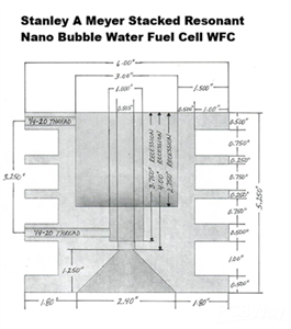
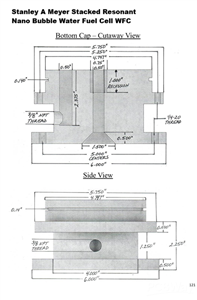
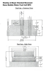

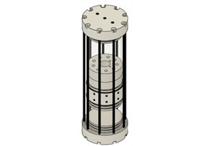
Stanley A Meyer Stack Resonant Cavity
Dynamysthesis: Force-Dominant Energy Release via Charge-Separated Fuel Collapse
1. Definition of Dynamysthesis (Engineering Context)
Dynamysthesis describes a force-first energy release mechanism in which chemically derived fuel is conditioned into a charge-separated, electron-deficient state prior to ignition, such that mechanical impulse (pressure / thrust) dominates over thermal dissipation during the initial reaction phase.
Unlike conventional combustion—where energy manifests primarily as heat due to rapid electron recombination—dynamysthetic fuel releases energy through electrostatic field collapse and momentum transfer before thermal equilibration occurs.
Join Us https://www.patreon.com/c/securesupplies
2. Charge State Conditioning: All-Positive Fuel Domain
In the stacked WFC architecture:
Fuel gases are produced under unipolar, positive-only voltage stimulation
No alternating polarity is applied
No negative return path (ground) is provided during conditioning
This results in:
Electron-deficient hydrogen and oxygen species
Net positive charge dominance across the fuel mass
Suppressed electron backflow during formation
From an engineering standpoint, the fuel exits the stack in a non-neutral plasma-adjacent molecular state, not a chemically balanced gas.
3. Absence of Ground and Electron Return
A critical requirement for dynamysthesis is intentional removal of electron equilibrium.
Engineering conditions enforced by the system:
No ground reference during fuel formation
High impedance voltage intensification
Gated pulse sequencing
Electron extraction above the stack
Electrons displaced during molecular elongation are:
Pulled away
Delayed from recombination
Routed externally or spatially isolated
This ensures that, at the moment of ignition, the fuel cannot immediately collapse into a thermal equilibrium state.
4. Ignition Phase: Force Before Heat
When the conditioned fuel is ignited:
Electrostatic field collapse occurs first
Rapid charge neutralization creates:
Intense Coulombic attraction
Sudden pressure expansion
Mechanical impulse is generated prior to full thermalization
This produces:
A pressure spike
High expansion velocity
Strong impulse suitable for mechanical work
Heat is a secondary byproduct, not the primary energy carrier in the first reaction interval.
5. The Donatelli Cycle (Closed Energy Loop Model)
The Donatelli Cycle describes the complete dynamysthetic loop:
Phase 1 – Polarization
Water molecules are aligned and elongated under high electric field strength.
Phase 2 – Electron Removal
Electrons are displaced and prevented from immediate return.
Phase 3 – Charge-Separated Fuel State
Fuel exists as a positively charged, electron-deficient nano-bubble gas.
Phase 4 – Force-Dominant Ignition
Electrostatic collapse produces mechanical impulse before heat.
Phase 5 – Electron Reacquisition
Post-expansion, electrons return from the environment.
Phase 6 – Molecular Reformation
Hydrogen and oxygen collapse back into water.
Phase 7 – Implosive Relaxation
The system transitions from expansion to recombination, completing the cycle.
This expansion → collapse sequence explains why the system can exhibit both explosive force and implosive recovery without violating conservation laws.
6. Implosion Back to Water (Post-Reaction Physics)
After force release:
Charge neutrality is restored
Electron balance returns
Molecular bonds re-form
This results in:
Rapid cooling
Volume contraction
Apparent “implosion” back toward water
From an engineering perspective, this is a dielectric relaxation event, not a chemical anomaly.
7. Why Dynamysthesis Produces More Force Than Heat
Key engineering reasons:
Energy stored in electric fields, not molecular vibration
Momentum transfer occurs before thermal diffusion
Reaction time constants favor pressure over temperature
Electron return is delayed, not instantaneous
This makes the fuel behavior closer to:
Electrostatic discharge mechanics
Plasma impulse phenomena
Field-collapse driven expansion
rather than classical flame-front combustion.
8. Engineering Implications
Dynamysthetic fuel is inherently suited for systems requiring:
High impulse density
Rapid expansion
Pressure-based energy transfer
Reduced waste heat
The stacked WFC with photon injection and electron management is therefore an energy conditioning system, not merely a gas generator.
9. Practical Summary
Fuel is charged before ignition
No ground = no premature electron collapse
Force is released before heat
Electron return occurs after work is done
Water reforms as part of the cycle
This completes the dynamysthetic / Donatelli Cycle.
Engineering Explanation of the Stanley A. Meyer Stacked WFC Nano-Bubble Water Fuel Cell with LED Injection
1. Why the Stacked WFC Was Created (Engineering Objective)
The stacked WFC architecture was created to solve four engineering problems simultaneously:
Increase gas production per unit input current
Maintain electrical isolation while scaling voltage
Control electron behavior during molecular dissociation
Condition the produced gas into a higher-energy, nano-structured state
From an engineering standpoint, stacking was not about brute-force electrolysis.
It was about field control, charge management, and residence time.
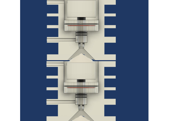
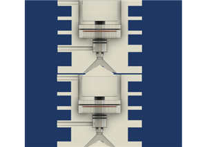
Each stacked cavity acts as:
A capacitive voltage domain
A nano-bubble generator
A photon–field interaction chamber
A charge-controlled flow stage
2. How the Stacked Cell Works (System-Level Physics)
2.1 Electrical Architecture: Voltage Without Current
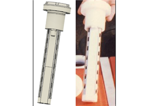
Each resonant cavity uses:
Coaxial stainless steel electrodes
A Voltage Intensifier Circuit (VIC)
Unipolar, gated, step-charging pulses
This creates:
High electric field strength
Extremely low electron current
From physics:
The system operates in a dielectric polarization regime
Water behaves as a nonlinear dielectric, not a resistive load
Voltage is increased incrementally (step-charging), allowing molecular polarization without electron recombination.
2.2 Why Stacking Matters Electrically
Stacking does three critical things:
Prevents voltage collapse
Each cavity is electrically isolated
Voltage builds independently per stage
Extends exposure time
Gas bubbles formed in the lower cell rise into the next
Each stage re-energizes the same molecules
Creates a vertical field gradient
Gas experiences multiple polarization zones
Acts as a field pump, not a pressure pump
This is functionally similar to multi-stage particle conditioning, not electrolysis.
3. Nano-Bubble Formation (Water Fuel Physics)
3.1 Why Nano-Bubbles Are Central
Under high electric field strength:
Gas nucleates as nano-scale bubbles
These bubbles have:
High surface charge
Extended lifetime
Increased gas–water interface energy
Nano-bubbles:
Store electrostatic energy
Carry net charge
Resist recombination
Stacking increases:
Bubble density
Bubble residence time
Bubble charge uniformity
4. LED Photon Injection: Engineering Purpose
4.1 Why LEDs Were Added
The LED system is not illumination.
It is photon-assisted charge destabilization.
Key engineering functions:
Inject photons at controlled pulse rates
Maintain gas atoms in an excited electronic state
Prevent re-bonding after electron displacement
From physics:
Photon energy increases electron orbital instability
Works synergistically with electric field elongation
Each cavity includes:
LED ring
Reflective Delrin geometry
Optical confinement cone
This increases:
Photon dwell time
Interaction probability
Gas excitation persistence
5. Electron Removal & Management (Critical Engineering Insight)
5.1 Why Removing Electrons Matters
In conventional electrolysis:
Electrons immediately recombine
Energy is lost as heat
In Meyer’s system:
Electrons are intentionally displaced
Replacement is electron-restricted
Mechanisms used:
Unipolar pulses
High impedance
Gated sequencing
Electron extraction circuit (above the stack)
Result:
Atoms remain electron-deficient
Gas exits the water in a non-equilibrium state
5.2 Electron Extraction Path
Above the stack:
Gas passes into the Gas Resonant Cavity
Additional voltage stimulation occurs
An electron extraction grid pulls liberated electrons
Engineering effect:
Prevents charge neutralization
Converts electron flow into usable electrical output
Maintains gas in a higher enthalpy condition
This is why:
More gas is produced per input watt
Gas carries higher reactive potential
6. Why the Gas Outlet Is on Top (Fluid + Charge Physics)
Top-exit gas flow is intentional:
Buoyancy-assisted staging
Minimal turbulence
Charge retention
Directional electron extraction
Gas rising upward:
Moves with the electric field gradient
Experiences sequential excitation
Avoids charge-scrubbing against water
This preserves:
Nano-bubble structure
Electron deficiency
Photon-induced excitation
7. Engineering Rationale for Turbine / High-Energy Use
From an engineering physics standpoint, the output gas differs from standard HHO:
Higher ionization fraction
Reduced electron population
Increased reaction rate upon ignition
Faster flame front propagation
These properties are advantageous for:
High-RPM combustion
Pressure-pulse systems
Turbine or expansion-based engines
The system conditions the gas before combustion rather than relying on combustion alone.
8. Why the Stacked WFC Is an Elegant Engineering System
From pure engineering analysis, the stacked WFC excels because it:
Separates voltage from current
Uses field effects instead of joule heating
Employs temporal control instead of brute force
Integrates electrical, optical, and fluid domains
Treats water as a dielectric medium, not a consumable electrolyte
9. Practical Engineering Summary (Actionable Takeaways)
The stack is a multi-stage field conditioner
LEDs provide photon-assisted electron destabilization
Electron extraction increases gas energy density
Nano-bubbles are the energy storage medium
Top-exit gas preserves charge and excitation
This is a systems-engineering solution, not a chemical trick.
Stanley A Meyer Stack Resonant Cavity
*PCBWay community is a sharing platform. We are not responsible for any design issues and parameter issues (board thickness, surface finish, etc.) you choose.


Raspberry Pi 5 7 Inch Touch Screen IPS 1024x600 HD LCD HDMI-compatible Display for RPI 4B 3B+ OPI 5 AIDA64 PC Secondary Screen(Without Speaker)
BUY NOW

- Comments(0)
- Likes(0)
More by Daniel Donatelli
-
 Stanley A Meyer VIC Voltage intensifier circuit transformer board v1.8 updated jan 11 2021
Stanley A Meyer VIC Voltage intensifier transformer board Join Support help change the World https:/...
Stanley A Meyer VIC Voltage intensifier circuit transformer board v1.8 updated jan 11 2021
Stanley A Meyer VIC Voltage intensifier transformer board Join Support help change the World https:/...
-
 STANLEY A MEYER LES BANKI AUTO START AUTO WATER FUEL REFILL
Join Support help change the World https:...
STANLEY A MEYER LES BANKI AUTO START AUTO WATER FUEL REFILL
STANLEY A MEYER LES BANKI AUTO START AUTO WATER FUEL REFILLJoin Support help change the World https:...
-
 Stanley A Meyer Gated Pulse Frequency Generator K3 with DB 37 updated 060622
Stanley A Meyer Gated Pulse Frequency Generator K3 with DB 37 to suit matrix vic main board Join Sup...
Stanley A Meyer Gated Pulse Frequency Generator K3 with DB 37 updated 060622
Stanley A Meyer Gated Pulse Frequency Generator K3 with DB 37 to suit matrix vic main board Join Sup...
-
 Stanley A Meyer K2 Variable Pulse Frequency Generator GMS Vic Matrix PCB Gerber
Stanley A Meyer K2 Variable Pulse Frequency Generator GMS Vic Matrix PCBGerberJoin Support help chan...
Stanley A Meyer K2 Variable Pulse Frequency Generator GMS Vic Matrix PCB Gerber
Stanley A Meyer K2 Variable Pulse Frequency Generator GMS Vic Matrix PCBGerberJoin Support help chan...
-
 Hyduino Stim Stimulator circuit board Ms EMS ECU
Join Support help change the World https://www.patre...
Hyduino Stim Stimulator circuit board Ms EMS ECU
Hyduino Stim Stimulator circuit board Ms EMS ECUJoin Support help change the World https://www.patre...
-
 Stanley A Meyer VIC Daughter Board Driver Transistor Circuit board Version 1
 Updated 28th Sept 2021 ...
Stanley A Meyer VIC Daughter Board Driver Transistor Circuit board Version 1
Stanley A Meyer VIC Daughter Board Driver Transistor Circuit board Version 1 Updated 28th Sept 2021 ...
-
 Stanley A Meyer VIC Daughter Board Driver USed with Variac EEC eleectron eextrract & chokes
Stanley A Meyer VIC Daughter Board Driver USed with Variac EEC eleectron extrract & chokes can d...
Stanley A Meyer VIC Daughter Board Driver USed with Variac EEC eleectron eextrract & chokes
Stanley A Meyer VIC Daughter Board Driver USed with Variac EEC eleectron extrract & chokes can d...
-
 Stanley A Meyer Taking Gas Management Warning Board Stans Voice
 Who Wants to Clone Stans Voice and M...
Stanley A Meyer Taking Gas Management Warning Board Stans Voice
Stanley A Meyer Taking Gas Management Warning Board Stans Voice Who Wants to Clone Stans Voice and M...
-
 Stanley A Meyer Stack Resonant Cavity
Dynamysthesis: Force-Dominant Energy Release via Charge-Separated Fuel Collapse1. Definition of Dyna...
Stanley A Meyer Stack Resonant Cavity
Dynamysthesis: Force-Dominant Energy Release via Charge-Separated Fuel Collapse1. Definition of Dyna...
-
 Stanley A Myer nano bubble water fuel 9 TUBE CELL Modern 3d Print
Join Us https://www.patreon.com/c/s...
Stanley A Myer nano bubble water fuel 9 TUBE CELL Modern 3d Print
Stanley A Myer nano bubble water fuel 9 TUBE CELL Modern 3d PrintJoin Us https://www.patreon.com/c/s...
-
 Stanley A Meyer Nano Bubble Water Fuel Tank Steam Defrost Resonator
Stanley A. Meyer Nano-Bubble Water Fuel Tank Steam Defrost ResonatorTechnical DescriptionJoin Us htt...
Stanley A Meyer Nano Bubble Water Fuel Tank Steam Defrost Resonator
Stanley A. Meyer Nano-Bubble Water Fuel Tank Steam Defrost ResonatorTechnical DescriptionJoin Us htt...
-
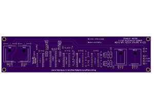
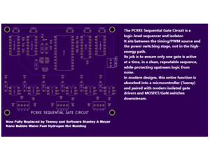 Stanley A Meyer PC9XE Sequential Gate Circuit
Ethan Replication Stanley A Meyer PC9XE Sequential Gate Circuit 1. Where This Board Fits in the Stan...
Stanley A Meyer PC9XE Sequential Gate Circuit
Ethan Replication Stanley A Meyer PC9XE Sequential Gate Circuit 1. Where This Board Fits in the Stan...
-
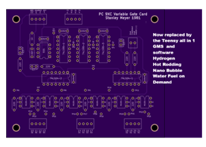 Stanley A Meyer PC9XC Variable Gate Card
Ethan Replication Stanley A Meyer Stanley A Meyer PC9XC Variable Gate CardJoin Us https://www.patreo...
Stanley A Meyer PC9XC Variable Gate Card
Ethan Replication Stanley A Meyer Stanley A Meyer PC9XC Variable Gate CardJoin Us https://www.patreo...
-
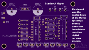 Stanley A Meyer PLL Gated Frequency Generator
Ethan Replication bom notes and advancing it Stanley A Meyer PLL Gated Frequency Generator2. Wher...
Stanley A Meyer PLL Gated Frequency Generator
Ethan Replication bom notes and advancing it Stanley A Meyer PLL Gated Frequency Generator2. Wher...
-
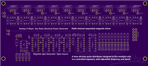 Stanley A Meyer EPG Magnetic Spin Gerbers MUlt i Trigger VIc or Coils
You’re looking at a multi-channel sequential magnetic driver. This is not a simple oscillator board ...
Stanley A Meyer EPG Magnetic Spin Gerbers MUlt i Trigger VIc or Coils
You’re looking at a multi-channel sequential magnetic driver. This is not a simple oscillator board ...
-
 Stanley A Meyer Steam Resonator PCB
1. Bill of Materials (BOM)Based on silkscreen labels visible on the PCB. Values are conservative and...
Stanley A Meyer Steam Resonator PCB
1. Bill of Materials (BOM)Based on silkscreen labels visible on the PCB. Values are conservative and...
-
 U-Core Bobbin for VIC Transformer | 8XA Stanley A. Meyer Style | Ferrite U126x91x20 | High-Voltage Experimental Coil Former
Stanley A. Meyer U-Core Bobbin – 8XA ConfigurationFerrite U-Core Bobbin for VIC / Water Fuel Cell Re...
U-Core Bobbin for VIC Transformer | 8XA Stanley A. Meyer Style | Ferrite U126x91x20 | High-Voltage Experimental Coil Former
Stanley A. Meyer U-Core Bobbin – 8XA ConfigurationFerrite U-Core Bobbin for VIC / Water Fuel Cell Re...
-
 Nano Second Laser Diode Driver STANLEY a MEYER Nano Bubble Water Fuel
 # Avalanche Laser Diode Driver...
Nano Second Laser Diode Driver STANLEY a MEYER Nano Bubble Water Fuel
Nano Second Laser Diode Driver STANLEY a MEYER Nano Bubble Water Fuel # Avalanche Laser Diode Driver...
-
Programmable Mist Maker - XIAO / QT PY Extension
867 1 0 -
RadioHAT - Raspberry Pi radio development platform
696 0 2 -
-
-
-
-
ARPS-2 – Arduino-Compatible Robot Project Shield for Arduino UNO
3166 0 6 -
A Compact Charging Breakout Board For Waveshare ESP32-C3
3782 3 8 -
AI-driven LoRa & LLM-enabled Kiosk & Food Delivery System
4125 2 2


