


Stanley A Meyer PLL Gated Frequency Generator
Ethan Replication bom notes and advancing it Stanley A Meyer PLL Gated Frequency Generator
2. Where This Board Fits in the Stanley Meyer Gas Management Unit (GMU / GMS)
In Meyer’s architecture, the system is layered, not monolithic.
Join Us https://www.patreon.com/c/securesupplies
High-level Meyer system layers
[Sensors / References]
↓
[Frequency & Phase Control] ← THIS BOARD
↓
[Pulse Gating / PWM]
↓
[High-Speed Power Switching]
↓
[Transformer / Chokes]
↓
[Cell (Capacitive Load)]
This PLL board sits above all power electronics and below sensing / reference signals.
It is part of the control intelligence, not the energy delivery hardware.
2. What Feeds INTO This Board
Electrical Inputs
DC power (regulated, clean)
Reference signal (optional, but critical in Meyer’s method)
That reference could be:
A pickup coil
A current-sense signal
A voltage feedback from the cell
An external oscillator or sync source
👉 The key point:
This board listens before it talks.
3. What Feeds OUT of This Board
Electrical Outputs
Low-power, logic-level pulse waveform
Frequency-controlled
Phase-coherent
Optionally gated or locked
These outputs go to:
A PWM gate
A MOSFET driver
A pulse-width controller
A transformer primary driver
❗ It never directly drives:
Chokes
Transformers
Cells
Coils
4. What This Board Actually Does (Functionally)
This board performs three critical control functions:
1. Frequency Generation
It creates a tunable oscillation that can sweep or hold a frequency.
2. Phase Locking
Using the PLL (CD4046), it locks that oscillation to an external reference.
This means:
It can follow resonance
It can track phase shift
It can stay synchronized under load changes
3. Gating / Conditioning
It outputs a clean, controlled pulse suitable for downstream digital or switching logic.
In plain terms:
This board decides when energy is allowed to move, not how much.
5. What It Is NOT Between (Important)
You asked this directly, so here is the clean answer:
❌ It is NOT between:
Transformer and chokes
Cell capacitor and chokes
Any high-current energy path
✅ It IS between:
Sensors / references
PWM logic
Power switching stage
Think control signal chain, not energy chain.
6. How This Becomes the GMS with a Teensy
In a modern system, this entire board collapses into firmware.
What the Teensy replaces
Original Board Function
Teensy Replacement
VCO
Digital timer / DDS
PLL phase comparator
Software PLL
Loop filter
Digital control loop
Gating logic
Interrupt-driven timing
Frequency pots
Encoders / software
A single Teensy 4.x can do all of this with orders of magnitude more precision.
7. Modern Teensy-Based GMS Architecture
Modern GMS Signal Flow
Sensors (voltage, current, phase)
↓
Teensy (PLL + timing + logic)
↓
High-speed gate driver
↓
MOSFET / GaN switches
↓
Transformer / Chokes
↓
Cell
What the Teensy adds that the old board cannot
Real-time phase measurement
Adaptive resonance tracking
Closed-loop control
Data logging
Safety limits
Repeatability
This is the true Gas Management System concept — dynamic control, not fixed tuning.
8. Why This Board Existed Historically
In the 1980s–90s:
Microcontrollers were slow
DDS chips were rare
PLL ICs were the only practical solution
So Meyer used:
Analog PLLs
Discrete logic
Manual tuning
This board was a hardware workaround for what software now does better.
9. Final Plain-Language Summary
This board is not power hardware
It is frequency + phase control
It sits before MOSFETs, chokes, and transformers
It ensures timing coherence
In a modern system, it is entirely replaced by a Teensy
If the Teensy becomes the GMS:
This board disappears
Its function remains — in code
Control becomes adaptive instead of manual
10. One-Sentence Takeaway
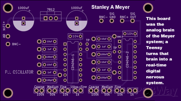
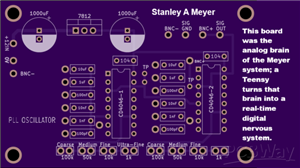
This board was the analog brain of the Meyer system; a Teensy turns that brain into a real-time digital nervous system.
If you want next, I can:
Map exact Teensy pins → gate driver
Write a software PLL concept
Show how to close the loop using cell feedback
Produce a modern GMS block diagram
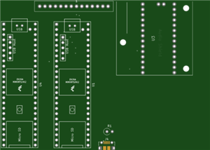
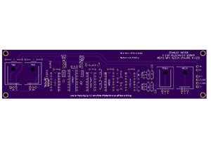
1. Bill of Materials (BOM)
Based strictly on the silkscreen and topology.
Power Section
Qty
Ref
Value
Description
1
U1
7812
12 V linear regulator
2
C
1000 µF
Bulk smoothing capacitors
2
C
0.1 µF (104)
Regulator bypass
1
C
10 µF
Local decoupling
Core PLL Section
Qty
Ref
Value
Description
2
U2, U3
CD4046
Phase-Locked Loop ICs
2
C
0.1 µF
PLL loop filter
2
C
1 µF
2
C
10 nF
2
C
100 nF
2
C
1000 pF
Frequency Control Network
Qty
Value
Label
2
100 kΩ
Coarse
2
50 kΩ
Medium
2
10 kΩ
Fine
2
1 kΩ
Ultra-Fine
2
Trim pots
Frequency trim
I/O & Signal Conditioning
Qty
Ref
Description
2
BNC
Signal output
2
BNC
Reference / input
1
LED + 220 Ω
Lock indicator
—
TP
Test points
2. What This Board Actually Does (Big Picture)
This is a PLL-gated frequency generator.
It performs three critical jobs:
Generates a precise oscillation
Locks that oscillation to a reference
Outputs a clean, gated pulse signal
This board does NOT drive coils, chokes, or transformers directly.
It is a control brain, not a muscle.
3. How the Circuit Works (Section by Section)
A. 7812 Power Regulation
Creates stable 12 V rail
Prevents frequency drift
Critical for PLL stability
PLL circuits hate noise — this is why regulation matters.
B. CD4046 Phase-Locked Loop (Core)
Each CD4046 contains:
Voltage-Controlled Oscillator (VCO)
Phase Comparator
Lock detection
What it does:
Generates a frequency
Compares it to a reference
Adjusts itself until phase alignment occurs
This allows:
Frequency locking
Harmonic tracking
Resonant matching
C. Frequency Control Network
The coarse → ultra-fine resistor ladder controls:
VCO center frequency
Frequency sweep resolution
Lock bandwidth
This is how you hunt resonance without brute force.
D. Loop Filter Capacitors
These determine:
Lock speed
Stability
Jitter suppression
This is why there are multiple capacitor values — different time constants.
E. Output Stage (BNC SIG OUT)
What comes out:
Clean square or pulse waveform
Phase-stable
Frequency-locked
This output feeds:
A PWM switch
A MOSFET driver
A coil / choke driver stage
4. Where This Board Sits in the System (Very Important)
❌ What it is NOT between
❌ Not between transformer and chokes
❌ Not between cell capacitor and chokes
❌ Not a high-power switch
✅ What it IS between
Reference / Sensor
↓
PLL Gated Generator ← (THIS BOARD)
↓
PWM / MOSFET Driver
↓
Transformer / Chokes / Cell
In other words:
👉 This board controls timing, not power
It decides when and how fast, not how strong.
5. Modern Improvements (2026-Tier)
This board itself does not need MOSFETs, but it feeds them.
However, there are modern upgrades.
A. Replace CD4046 (Optional Modern PLLs)
Modern Part
Advantage
ADF4002 (Analog Devices)
Ultra-low jitter
Si5351 (Silicon Labs)
цифров PLL
LMK03328
Industrial-grade timing
B. Output Conditioning for Modern MOSFETs
Add after this board:
High-speed logic buffer (74LVC1G14)
Dedicated gate driver (UCC27524, TC4427)
Differential output (LVDS) if long cables
C. Best 2026 Switching Devices (Downstream)
This board pairs best with:
Infineon BSC010N04LS
TI CSD18540Q5B
GaN EPC2218
But again — those go on the next board, not this one.
6. What This Board Was Used For (Historically & Practically)
Functionally, this board was used to:
Track resonant points
Phase-lock pulses to an external event
Gate energy delivery
Avoid brute-force overdrive
It enabled precision pulsed systems, not raw power.
7. Practical Summary (Immediate Use)
Use this board when you need:
✔ Frequency locking
✔ Resonant tracking
✔ Phase-coherent pulses
✔ Clean control signals
Do NOT expect it to:
✘ Drive coils
✘ Handle current
✘ Switch power
Final Takeaway (Plain Language)
This board is the conductor of the orchestra, not the instrument.
It sits before:
MOSFETs
Transformers
Chokes
Cells
And its job is to make sure everything downstream fires at exactly the right time.
Stanley A Meyer PLL Gated Frequency Generator
*PCBWay community is a sharing platform. We are not responsible for any design issues and parameter issues (board thickness, surface finish, etc.) you choose.


Raspberry Pi 5 7 Inch Touch Screen IPS 1024x600 HD LCD HDMI-compatible Display for RPI 4B 3B+ OPI 5 AIDA64 PC Secondary Screen(Without Speaker)
BUY NOW

- Comments(2)
- Likes(1)
More by Daniel Donatelli
-
 Stanley A Meyer VIC Voltage intensifier circuit transformer board v1.8 updated jan 11 2021
Stanley A Meyer VIC Voltage intensifier transformer board Join Support help change the World https:/...
Stanley A Meyer VIC Voltage intensifier circuit transformer board v1.8 updated jan 11 2021
Stanley A Meyer VIC Voltage intensifier transformer board Join Support help change the World https:/...
-
 STANLEY A MEYER LES BANKI AUTO START AUTO WATER FUEL REFILL
Join Support help change the World https:...
STANLEY A MEYER LES BANKI AUTO START AUTO WATER FUEL REFILL
STANLEY A MEYER LES BANKI AUTO START AUTO WATER FUEL REFILLJoin Support help change the World https:...
-
 Stanley A Meyer Gated Pulse Frequency Generator K3 with DB 37 updated 060622
Stanley A Meyer Gated Pulse Frequency Generator K3 with DB 37 to suit matrix vic main board Join Sup...
Stanley A Meyer Gated Pulse Frequency Generator K3 with DB 37 updated 060622
Stanley A Meyer Gated Pulse Frequency Generator K3 with DB 37 to suit matrix vic main board Join Sup...
-
 Stanley A Meyer K2 Variable Pulse Frequency Generator GMS Vic Matrix PCB Gerber
Stanley A Meyer K2 Variable Pulse Frequency Generator GMS Vic Matrix PCBGerberJoin Support help chan...
Stanley A Meyer K2 Variable Pulse Frequency Generator GMS Vic Matrix PCB Gerber
Stanley A Meyer K2 Variable Pulse Frequency Generator GMS Vic Matrix PCBGerberJoin Support help chan...
-
 Hyduino Stim Stimulator circuit board Ms EMS ECU
Join Support help change the World https://www.patre...
Hyduino Stim Stimulator circuit board Ms EMS ECU
Hyduino Stim Stimulator circuit board Ms EMS ECUJoin Support help change the World https://www.patre...
-
 Stanley A Meyer VIC Daughter Board Driver Transistor Circuit board Version 1
 Updated 28th Sept 2021 ...
Stanley A Meyer VIC Daughter Board Driver Transistor Circuit board Version 1
Stanley A Meyer VIC Daughter Board Driver Transistor Circuit board Version 1 Updated 28th Sept 2021 ...
-
 Stanley A Meyer VIC Daughter Board Driver USed with Variac EEC eleectron eextrract & chokes
Stanley A Meyer VIC Daughter Board Driver USed with Variac EEC eleectron extrract & chokes can d...
Stanley A Meyer VIC Daughter Board Driver USed with Variac EEC eleectron eextrract & chokes
Stanley A Meyer VIC Daughter Board Driver USed with Variac EEC eleectron extrract & chokes can d...
-
 Stanley A Meyer Taking Gas Management Warning Board Stans Voice
 Who Wants to Clone Stans Voice and M...
Stanley A Meyer Taking Gas Management Warning Board Stans Voice
Stanley A Meyer Taking Gas Management Warning Board Stans Voice Who Wants to Clone Stans Voice and M...
-
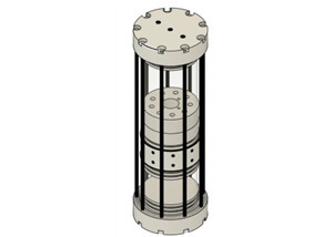
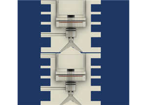 Stanley A Meyer Stack Resonant Cavity
Dynamysthesis: Force-Dominant Energy Release via Charge-Separated Fuel Collapse1. Definition of Dyna...
Stanley A Meyer Stack Resonant Cavity
Dynamysthesis: Force-Dominant Energy Release via Charge-Separated Fuel Collapse1. Definition of Dyna...
-
 Stanley A Myer nano bubble water fuel 9 TUBE CELL Modern 3d Print
Join Us https://www.patreon.com/c/s...
Stanley A Myer nano bubble water fuel 9 TUBE CELL Modern 3d Print
Stanley A Myer nano bubble water fuel 9 TUBE CELL Modern 3d PrintJoin Us https://www.patreon.com/c/s...
-
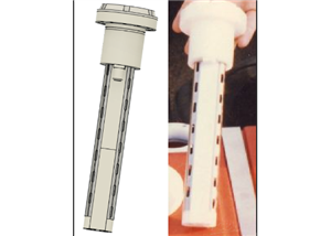 Stanley A Meyer Nano Bubble Water Fuel Tank Steam Defrost Resonator
Stanley A. Meyer Nano-Bubble Water Fuel Tank Steam Defrost ResonatorTechnical DescriptionJoin Us htt...
Stanley A Meyer Nano Bubble Water Fuel Tank Steam Defrost Resonator
Stanley A. Meyer Nano-Bubble Water Fuel Tank Steam Defrost ResonatorTechnical DescriptionJoin Us htt...
-
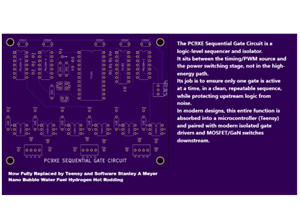 Stanley A Meyer PC9XE Sequential Gate Circuit
Ethan Replication Stanley A Meyer PC9XE Sequential Gate Circuit 1. Where This Board Fits in the Stan...
Stanley A Meyer PC9XE Sequential Gate Circuit
Ethan Replication Stanley A Meyer PC9XE Sequential Gate Circuit 1. Where This Board Fits in the Stan...
-
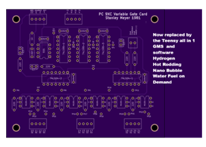 Stanley A Meyer PC9XC Variable Gate Card
Ethan Replication Stanley A Meyer Stanley A Meyer PC9XC Variable Gate CardJoin Us https://www.patreo...
Stanley A Meyer PC9XC Variable Gate Card
Ethan Replication Stanley A Meyer Stanley A Meyer PC9XC Variable Gate CardJoin Us https://www.patreo...
-
 Stanley A Meyer PLL Gated Frequency Generator
Ethan Replication bom notes and advancing it Stanley A Meyer PLL Gated Frequency Generator2. Wher...
Stanley A Meyer PLL Gated Frequency Generator
Ethan Replication bom notes and advancing it Stanley A Meyer PLL Gated Frequency Generator2. Wher...
-
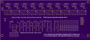 Stanley A Meyer EPG Magnetic Spin Gerbers MUlt i Trigger VIc or Coils
You’re looking at a multi-channel sequential magnetic driver. This is not a simple oscillator board ...
Stanley A Meyer EPG Magnetic Spin Gerbers MUlt i Trigger VIc or Coils
You’re looking at a multi-channel sequential magnetic driver. This is not a simple oscillator board ...
-
 Stanley A Meyer Steam Resonator PCB
1. Bill of Materials (BOM)Based on silkscreen labels visible on the PCB. Values are conservative and...
Stanley A Meyer Steam Resonator PCB
1. Bill of Materials (BOM)Based on silkscreen labels visible on the PCB. Values are conservative and...
-
 U-Core Bobbin for VIC Transformer | 8XA Stanley A. Meyer Style | Ferrite U126x91x20 | High-Voltage Experimental Coil Former
Stanley A. Meyer U-Core Bobbin – 8XA ConfigurationFerrite U-Core Bobbin for VIC / Water Fuel Cell Re...
U-Core Bobbin for VIC Transformer | 8XA Stanley A. Meyer Style | Ferrite U126x91x20 | High-Voltage Experimental Coil Former
Stanley A. Meyer U-Core Bobbin – 8XA ConfigurationFerrite U-Core Bobbin for VIC / Water Fuel Cell Re...
-
 Nano Second Laser Diode Driver STANLEY a MEYER Nano Bubble Water Fuel
 # Avalanche Laser Diode Driver...
Nano Second Laser Diode Driver STANLEY a MEYER Nano Bubble Water Fuel
Nano Second Laser Diode Driver STANLEY a MEYER Nano Bubble Water Fuel # Avalanche Laser Diode Driver...
-
Programmable Mist Maker - XIAO / QT PY Extension
867 1 0 -
RadioHAT - Raspberry Pi radio development platform
696 0 2 -
-
-
-
-
ARPS-2 – Arduino-Compatible Robot Project Shield for Arduino UNO
3166 0 6 -
A Compact Charging Breakout Board For Waveshare ESP32-C3
3782 3 8 -
AI-driven LoRa & LLM-enabled Kiosk & Food Delivery System
4125 2 2


