


Power Management Board for Battery Powered Projects
Introduction
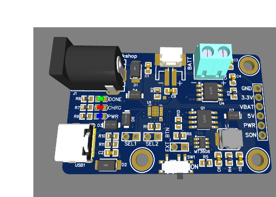
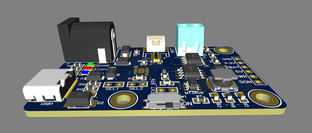
The LiPo Power Board functions as a power controller for devices powered by batteries, mainly aimed at prototyping use due to its breakout-style design. It operates with a single 3.7V LiPo cell and delivers two voltage outputs: a stable 3.3V and another adjustable output that can supply higher voltage and current levels. A built-in switch enables users to turn off power to both outputs when needed. The board supports battery charging through USB-C and DC jack connectors.
One of its key advantages is the flexible boost converter section, where the output voltage can be easily modified by adjusting the ratio of two resistors. This design also allows duplication of the boost circuit to create additional voltage outputs if required.This board is particularly useful in applications where a microcontroller operates at 3.3V while other components, such as sensors or devices like WS2812B LEDs, require a higher and more stable voltage supply.
For Full Project:
https://electronicsworkshops.com/power-management-board-for-battery-powered-projects/
Features
Low leakage current design for improved battery efficiency
3.81mm pin spacing for easy integration and compatibility
Includes 3D model support for accurate design and enclosure planning
Minimum guaranteed output current at 5V: over 400mA (tested at 3.3V input)
Circuit Diagram
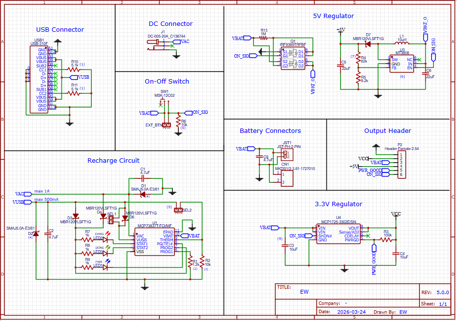
This circuit is a complete LiPo battery power management system that includes charging, voltage regulation, protection, and multiple output rails (3.3V and boosted 5V). It is divided into functional blocks:
1. Input Power Section (USB & DC Connector)
The board accepts input power from:
USB connector (USB1)
DC jack (DC-005-20A)
Input protection includes:
TVS diode (SMAJ5.0A) (Note 4) to suppress voltage spikes
Schottky diodes to prevent reverse current flow
USB resistors (R10, R11 = 5.1kΩ) configure proper USB-C behavior.
2. On-Off Control Circuit
A physical switch (SW1) controls the ON_SIG signal.
A pull-down resistor (R6) (Note 5) ensures the system does not power up unintentionally.
This signal enables/disables regulators and boost circuits.
3. Battery Charging Circuit
Main IC: MCP73831T LiPo charger
Key features:
Supports charging from USB (max 500mA) or DC input (up to 1A)
Charge current is set by R2 (1kΩ) (Note 2)
→ Increasing/decreasing this resistor changes charging current.
Status LEDs (D7, D8, D9) indicate charging states.
Protection:
Input current limiting resistors and diodes
Capacitors (C1, C2) for filtering
Temperature sensing:
Placeholder resistor for thermistor (Note 3)
→ Can be replaced with a real battery temperature sensor.
Special mode:
Can operate as LDO (no battery) (Note 5)
→ Requires Vtherm > Vdd – 100mV (SEL configuration).
4. Battery Connector
JST connector provides connection to the 3.7V LiPo battery
Includes decoupling capacitor (C7 = 4.7µF) for stability.
5. 3.3V Regulator Section
IC: MCP1725 LDO regulator
Converts VBAT → stable 3.3V output (VCC)
Features:
Low dropout voltage
Enable control via ON_SIG
Capacitors:
Input/output capacitors ensure stability (Note 9: Cin ≥ Cout and placed close to VIN)
6. 5V Boost Converter Section
IC: MT3606 boost converter
Steps up battery voltage (3.0–4.2V) → 5V output
Output voltage set by resistor divider: Vo = 0.6 × (1 + R4/R5) (Note 7)
Inductor (L1 = 10µH) and diode (Schottky) are essential for boost operation.
Important limitation:
The MT3606 cannot fully disconnect output (Note 6)
→ Even when EN is LOW, leakage path from VBAT to 5V exists.
Schottky diode drop:
Around 0.35V at 2A (Note 8), affecting efficiency.
7. Load Switch / Power Gating
MOSFET array (Q1) controls power delivery to outputs.
Ensures safe switching of voltage rails.
Controlled via ON_SIG signal.
8. Output Header
Provides multiple accessible signals:
VCC (3.3V)
VBAT (raw battery voltage)
+5V (boost output)
PWR_GOOD
ON_SIG control
For Full Project:
https://electronicsworkshops.com/power-management-board-for-battery-powered-projects/
Conclusion
The LiPo Power Board presents a well-integrated and flexible solution for managing power in battery-operated electronic systems. By combining efficient LiPo charging, stable 3.3V regulation, and an adjustable boost converter for higher voltage needs, it supports a wide range of components within a single compact design. Additional features such as input protection, power control switching, and configurable charging parameters enhance its reliability and adaptability. Despite minor limitations like boost converter leakage, the overall design makes it highly suitable for prototyping and embedded applications requiring multiple voltage levels from a single LiPo battery.
Power Management Board for Battery Powered Projects
Project images are for reference only. Actual production is based on the manufacturing files on the project page.
Please review the designer's notes (e.g., PCB thickness) and select the appropriate options.
PCBWay is not responsible
for issues caused by unsuitable parameter selections.
For more important ordering information, please refer to
Read More


Raspberry Pi 5 7 Inch Touch Screen IPS 1024x600 HD LCD HDMI-compatible Display for RPI 4B 3B+ OPI 5 AIDA64 PC Secondary Screen(Without Speaker)
BUY NOW

- Comments(0)
- Likes(1)
More by Rabin Poudel
-
 Automatic Water Pump Control System Using ESP-12F
IntroductionWater scarcity and wastage are major challenges in residential, agricultural, and indust...
Automatic Water Pump Control System Using ESP-12F
IntroductionWater scarcity and wastage are major challenges in residential, agricultural, and indust...
-
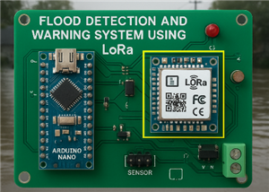 Flood Detection and warning system using LORA and Arduino
IntroductionFloods are one of the most devastating natural disasters, causing immense damage to life...
Flood Detection and warning system using LORA and Arduino
IntroductionFloods are one of the most devastating natural disasters, causing immense damage to life...
-
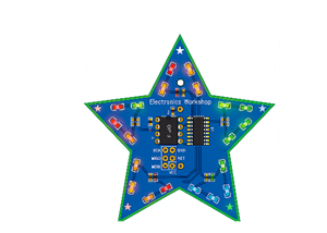 DIY LED Decoration Tiny Star PCB Project
IntroductionThe Tiny Star PCB is a small and fun DIY electronics project that is perfect for hobbyis...
DIY LED Decoration Tiny Star PCB Project
IntroductionThe Tiny Star PCB is a small and fun DIY electronics project that is perfect for hobbyis...
-
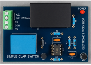 Simple and Cheap Clap Switch Circuit
IntroductionThe Simple and Cheap Clap Switch Circuit is a practical and fun DIY electronics project ...
Simple and Cheap Clap Switch Circuit
IntroductionThe Simple and Cheap Clap Switch Circuit is a practical and fun DIY electronics project ...
-
 Arduino-based Mist Maker and Hand Dryer
IntroductionIn today’s world, automation and hygiene have become essential, especially in public pla...
Arduino-based Mist Maker and Hand Dryer
IntroductionIn today’s world, automation and hygiene have become essential, especially in public pla...
-
 MPL3115A2 Barometric Pressure, Altitude, and Temperature Sensor
IntroductionThe MPL3115A2 is a highly accurate, low-power digital barometric pressure sensor from NX...
MPL3115A2 Barometric Pressure, Altitude, and Temperature Sensor
IntroductionThe MPL3115A2 is a highly accurate, low-power digital barometric pressure sensor from NX...
-
 E-Speaker Using ESP32
IntroductionThe E-Speaker is a smart, portable, and versatile audio system built using the ESP32 mic...
E-Speaker Using ESP32
IntroductionThe E-Speaker is a smart, portable, and versatile audio system built using the ESP32 mic...
-
 Heart Rate Monitor Circuit Using Photoplethysmography (PPG)
IntroductionHeart rate is a vital physiological parameter that reflects the health and fitness of an...
Heart Rate Monitor Circuit Using Photoplethysmography (PPG)
IntroductionHeart rate is a vital physiological parameter that reflects the health and fitness of an...
-
 Automated Greenhouse Control System using ESP32
IntroductionAn automated greenhouse control system leverages technology to optimize plant growth con...
Automated Greenhouse Control System using ESP32
IntroductionAn automated greenhouse control system leverages technology to optimize plant growth con...
-
 STD CH330N USB to Serial Converter 5V
IntroductionThe CH330N is a versatile USB-to-serial converter chip that simplifies interfacing betwe...
STD CH330N USB to Serial Converter 5V
IntroductionThe CH330N is a versatile USB-to-serial converter chip that simplifies interfacing betwe...
-
 KY-032 Obstacle avoidance sensor module
IntroductionIntroduction to Obstacle Avoidance SensorsObstacle avoidance sensors are essential compo...
KY-032 Obstacle avoidance sensor module
IntroductionIntroduction to Obstacle Avoidance SensorsObstacle avoidance sensors are essential compo...
-
 BC547 BASED WATER LEVEL INDICATOR
IntroductionA water level indicator using a BC547 transistor is a simple and effective electronic pr...
BC547 BASED WATER LEVEL INDICATOR
IntroductionA water level indicator using a BC547 transistor is a simple and effective electronic pr...
-
 How to Design Own Arduino Wifi shield PCB
OverviewArduino wifi shield connects the Arduino with a wifi chip through the serial communication p...
How to Design Own Arduino Wifi shield PCB
OverviewArduino wifi shield connects the Arduino with a wifi chip through the serial communication p...
-
 DIY Air Quality Tester
OverviewIn this project “DIY Air Quality Tester” we use Node MCU microcontroller and air quality sen...
DIY Air Quality Tester
OverviewIn this project “DIY Air Quality Tester” we use Node MCU microcontroller and air quality sen...
-
 Digital Clock Using Arduino
OverviewIn this project, “Digital clock using Arduino” we will make a PCB board for digital clock an...
Digital Clock Using Arduino
OverviewIn this project, “Digital clock using Arduino” we will make a PCB board for digital clock an...
-
 Bluetooth Controlled car using Arduino
OverviewA Bluetooth Controlled Car Using Arduino is a fascinating DIY project that involves building...
Bluetooth Controlled car using Arduino
OverviewA Bluetooth Controlled Car Using Arduino is a fascinating DIY project that involves building...
-
 Design a Magnetic Sensor Using S411A
IntroductionMagnetic sensors are widely used in modern electronic systems for detecting the presence...
Design a Magnetic Sensor Using S411A
IntroductionMagnetic sensors are widely used in modern electronic systems for detecting the presence...
-
 Design Simple Touch Sensor Using LM324
IntroductionTouch sensors have become an essential part of modern electronic devices, replacing trad...
Design Simple Touch Sensor Using LM324
IntroductionTouch sensors have become an essential part of modern electronic devices, replacing trad...
-
Programmable Mist Maker - XIAO / QT PY Extension
1037 2 1 -
RadioHAT - Raspberry Pi radio development platform
841 0 2 -
-
-
-
-
ARPS-2 – Arduino-Compatible Robot Project Shield for Arduino UNO
3296 0 6 -
A Compact Charging Breakout Board For Waveshare ESP32-C3
3914 3 8 -
AI-driven LoRa & LLM-enabled Kiosk & Food Delivery System
4292 2 2


