ESP8266 Programmer Board (USB-C Based)
Introduction
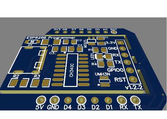
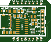
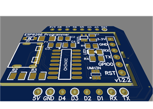
The ESP8266 Programmer is a compact breakout board designed to simplify firmware uploading and serial communication for ESP8266 modules (such as ESP-01, ESP-12, etc.).
It integrates power regulation, USB-to-serial conversion, and automatic boot mode control into a single board. The inclusion of a USB-C connector ensures modern compatibility, improved durability, and reliable power/data transfer.
For Full Project:
https://electronicsworkshops.com/esp8266-programmer-board-usb-c-based/
Objectives
Provide a plug-and-play solution for ESP8266 programming
Eliminate the need for external FTDI modules and manual wiring
Ensure stable 3.3V power supply
Enable automatic flashing mode (no manual GPIO switching)
Use modern USB-C interface
Block diagram
The block diagram shows the overall flow of the system. Power and data enter through the USB-C connector, where the protection circuit (diode and fuse) ensures safe operation. The voltage regulator converts 5V to a stable 3.3V required by the ESP8266. Meanwhile, the CH340C converts USB data into UART signals for communication. The auto-program circuit, controlled by RTS and DTR signals, manages GPIO0 and RST pins to automatically switch the ESP8266 into programming mode. All blocks work together to provide a seamless programming interface.
Circuit Diagram Explanation
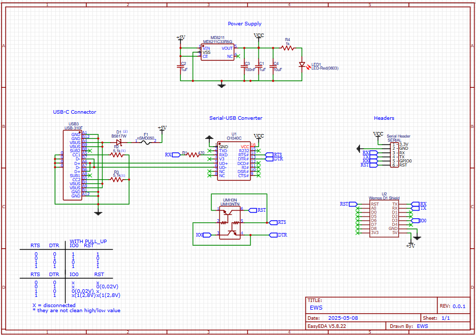
In the circuit diagram, the USB-C connector supplies 5V, which is protected using a Schottky diode and fuse before feeding the ME6211 LDO regulator to generate a stable 3.3V output. Capacitors are placed at input and output for filtering, and an LED indicates power status. The CH340C USB-to-serial converter connects to USB data lines (D+ and D−) and provides TX/RX communication to the ESP8266. The RTS and DTR pins from CH340C are routed through a dual NPN transistor (UMH3N), which automatically controls the ESP8266’s GPIO0 and RST pins for flashing. Finally, header pins expose power, serial, and control signals, allowing easy connection to ESP8266 modules like ESP-01 or D1 Mini.
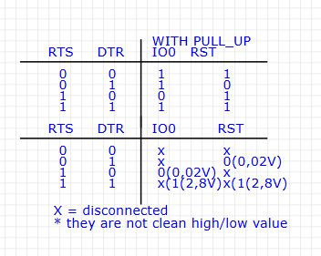
This table shows how RTS and DTR signals control GPIO0 (IO0) and RST for automatic programming of the ESP8266. With pull-up resistors, both IO0 and RST stay HIGH by default. When RTS/DTR change states, the transistor circuit pulls IO0 LOW and toggles RST to put the ESP8266 into flashing mode; otherwise, it stays in normal boot mode.
The second part shows real voltage behavior, where signals are not perfectly HIGH/LOW. Values like 0.02V (LOW) and 1.2–2.8V (uncertain) appear due to transistor switching. “X” means the pin is not actively driven. Despite this, the circuit works reliably for auto reset and programming.
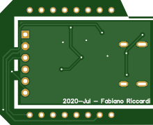
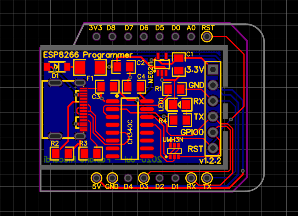
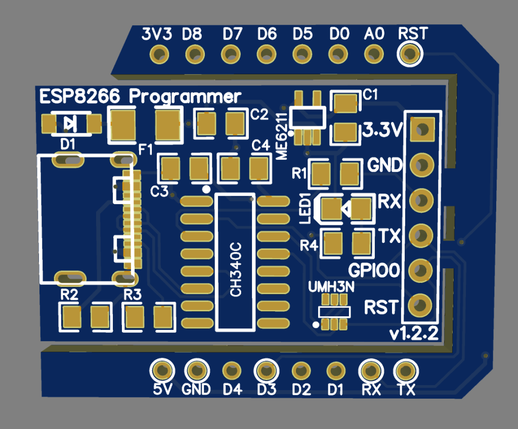
PCB Files
Conclusion
The ESP8266 Programmer Board with USB-C is an efficient and modern solution for developers working with ESP8266 modules. By combining power regulation, USB-to-serial conversion, and automatic boot control into a single compact board, it significantly simplifies firmware uploading and debugging.
This design improves reliability, reduces wiring complexity, and enhances user experience—making it ideal for both beginners and professionals in embedded systems and IoT development.
For Full Project:
https://electronicsworkshops.com/esp8266-programmer-board-usb-c-based/
ESP8266 Programmer Board (USB-C Based)
*PCBWay community is a sharing platform. We are not responsible for any design issues and parameter issues (board thickness, surface finish, etc.) you choose.


Raspberry Pi 5 7 Inch Touch Screen IPS 1024x600 HD LCD HDMI-compatible Display for RPI 4B 3B+ OPI 5 AIDA64 PC Secondary Screen(Without Speaker)
BUY NOW


- Comments(0)
- Likes(0)
More by Rabin Poudel
-
 Automatic Water Pump Control System Using ESP-12F
IntroductionWater scarcity and wastage are major challenges in residential, agricultural, and indust...
Automatic Water Pump Control System Using ESP-12F
IntroductionWater scarcity and wastage are major challenges in residential, agricultural, and indust...
-
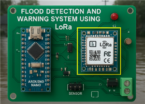 Flood Detection and warning system using LORA and Arduino
IntroductionFloods are one of the most devastating natural disasters, causing immense damage to life...
Flood Detection and warning system using LORA and Arduino
IntroductionFloods are one of the most devastating natural disasters, causing immense damage to life...
-
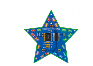 DIY LED Decoration Tiny Star PCB Project
IntroductionThe Tiny Star PCB is a small and fun DIY electronics project that is perfect for hobbyis...
DIY LED Decoration Tiny Star PCB Project
IntroductionThe Tiny Star PCB is a small and fun DIY electronics project that is perfect for hobbyis...
-
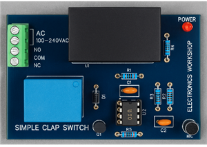 Simple and Cheap Clap Switch Circuit
IntroductionThe Simple and Cheap Clap Switch Circuit is a practical and fun DIY electronics project ...
Simple and Cheap Clap Switch Circuit
IntroductionThe Simple and Cheap Clap Switch Circuit is a practical and fun DIY electronics project ...
-
 Arduino-based Mist Maker and Hand Dryer
IntroductionIn today’s world, automation and hygiene have become essential, especially in public pla...
Arduino-based Mist Maker and Hand Dryer
IntroductionIn today’s world, automation and hygiene have become essential, especially in public pla...
-
 MPL3115A2 Barometric Pressure, Altitude, and Temperature Sensor
IntroductionThe MPL3115A2 is a highly accurate, low-power digital barometric pressure sensor from NX...
MPL3115A2 Barometric Pressure, Altitude, and Temperature Sensor
IntroductionThe MPL3115A2 is a highly accurate, low-power digital barometric pressure sensor from NX...
-
 E-Speaker Using ESP32
IntroductionThe E-Speaker is a smart, portable, and versatile audio system built using the ESP32 mic...
E-Speaker Using ESP32
IntroductionThe E-Speaker is a smart, portable, and versatile audio system built using the ESP32 mic...
-
 Heart Rate Monitor Circuit Using Photoplethysmography (PPG)
IntroductionHeart rate is a vital physiological parameter that reflects the health and fitness of an...
Heart Rate Monitor Circuit Using Photoplethysmography (PPG)
IntroductionHeart rate is a vital physiological parameter that reflects the health and fitness of an...
-
 Automated Greenhouse Control System using ESP32
IntroductionAn automated greenhouse control system leverages technology to optimize plant growth con...
Automated Greenhouse Control System using ESP32
IntroductionAn automated greenhouse control system leverages technology to optimize plant growth con...
-
 STD CH330N USB to Serial Converter 5V
IntroductionThe CH330N is a versatile USB-to-serial converter chip that simplifies interfacing betwe...
STD CH330N USB to Serial Converter 5V
IntroductionThe CH330N is a versatile USB-to-serial converter chip that simplifies interfacing betwe...
-
 KY-032 Obstacle avoidance sensor module
IntroductionIntroduction to Obstacle Avoidance SensorsObstacle avoidance sensors are essential compo...
KY-032 Obstacle avoidance sensor module
IntroductionIntroduction to Obstacle Avoidance SensorsObstacle avoidance sensors are essential compo...
-
 BC547 BASED WATER LEVEL INDICATOR
IntroductionA water level indicator using a BC547 transistor is a simple and effective electronic pr...
BC547 BASED WATER LEVEL INDICATOR
IntroductionA water level indicator using a BC547 transistor is a simple and effective electronic pr...
-
 How to Design Own Arduino Wifi shield PCB
OverviewArduino wifi shield connects the Arduino with a wifi chip through the serial communication p...
How to Design Own Arduino Wifi shield PCB
OverviewArduino wifi shield connects the Arduino with a wifi chip through the serial communication p...
-
 DIY Air Quality Tester
OverviewIn this project “DIY Air Quality Tester” we use Node MCU microcontroller and air quality sen...
DIY Air Quality Tester
OverviewIn this project “DIY Air Quality Tester” we use Node MCU microcontroller and air quality sen...
-
 Digital Clock Using Arduino
OverviewIn this project, “Digital clock using Arduino” we will make a PCB board for digital clock an...
Digital Clock Using Arduino
OverviewIn this project, “Digital clock using Arduino” we will make a PCB board for digital clock an...
-
 Bluetooth Controlled car using Arduino
OverviewA Bluetooth Controlled Car Using Arduino is a fascinating DIY project that involves building...
Bluetooth Controlled car using Arduino
OverviewA Bluetooth Controlled Car Using Arduino is a fascinating DIY project that involves building...
-
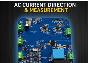 AC Current Direction & Measurement with Arduino Pro Micro
IntroductionWith the increasing adoption of renewable energy systems and smart energy management sol...
AC Current Direction & Measurement with Arduino Pro Micro
IntroductionWith the increasing adoption of renewable energy systems and smart energy management sol...
-
 ESP8266 Programmer Board (USB-C Based)
IntroductionThe ESP8266 Programmer is a compact breakout board designed to simplify firmware uploadi...
ESP8266 Programmer Board (USB-C Based)
IntroductionThe ESP8266 Programmer is a compact breakout board designed to simplify firmware uploadi...
-
Programmable Mist Maker - XIAO / QT PY Extension
62 0 0 -
-
-
-
-
-
ARPS-2 – Arduino-Compatible Robot Project Shield for Arduino UNO
2708 0 5 -
A Compact Charging Breakout Board For Waveshare ESP32-C3
3207 3 8 -
AI-driven LoRa & LLM-enabled Kiosk & Food Delivery System
3463 2 2