


|
|
MAX7219 |
x 1 |

|
arduino IDEArduino
|
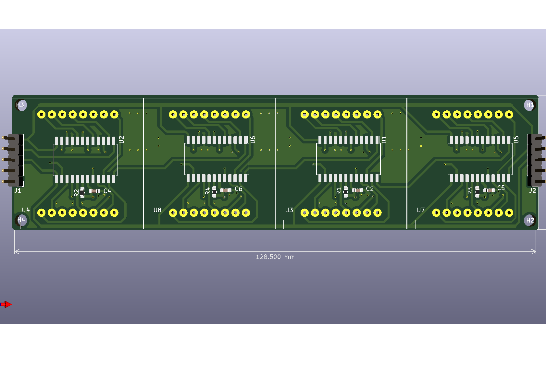
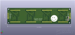
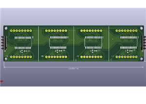
Matrix panel 8x32 3mm dot
Hi makers!
### **8x32 Common Anode LED Matrix Panel **
**Overview**
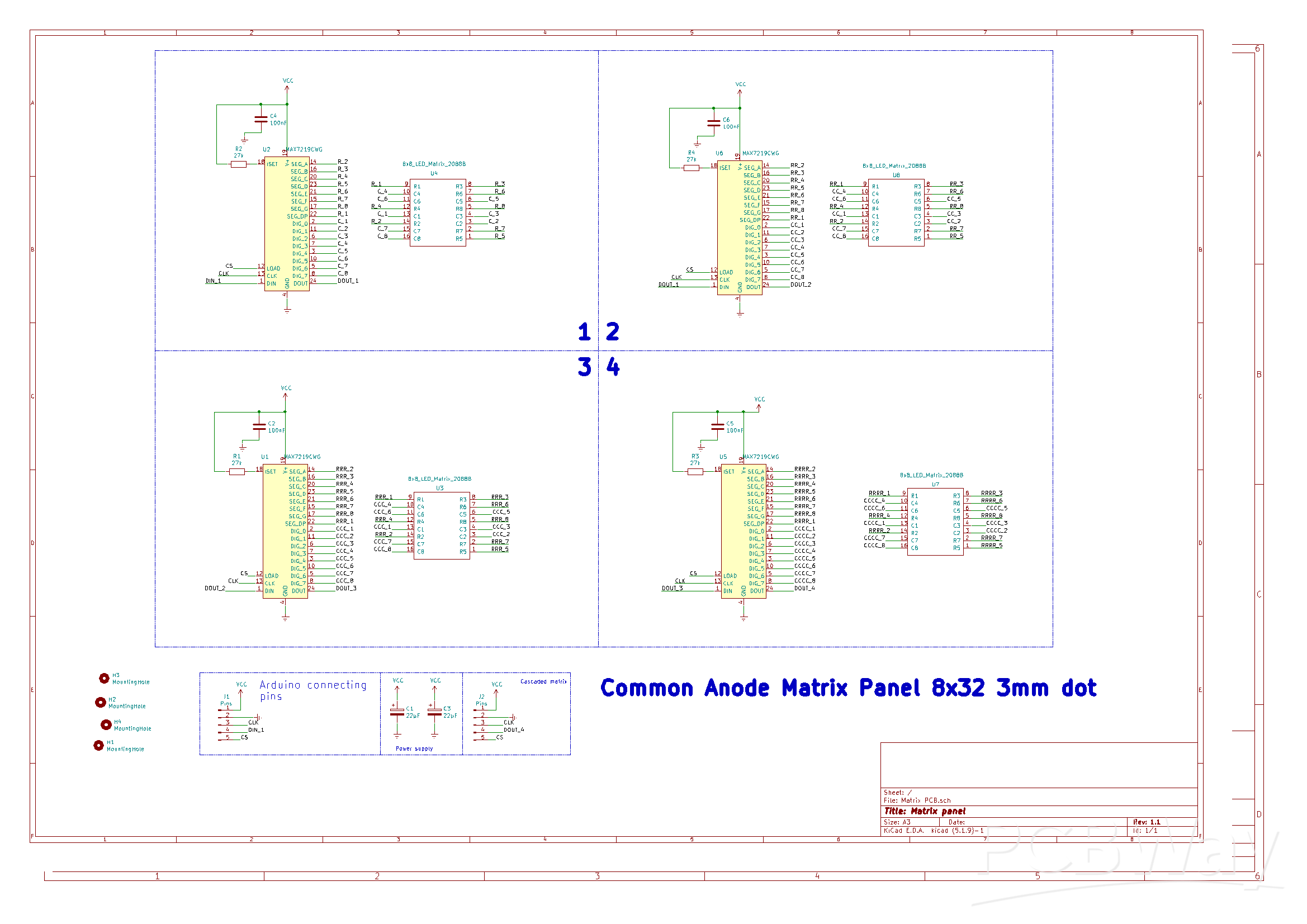
This schematic designs a driver board for a large **8x32 LED display** (8 rows high, 32 columns wide). It is constructed by chaining four standard 8x8 LED matrix modules together. The circuit is designed to be controlled by microcontrollers like Arduino, ESP32, or Raspberry Pi using a standard 3-wire serial interface (SPI-like).
**Key Components**
1. **Driver ICs (MAX7219CWG):**
* There are four **MAX7219** chips (labeled U1, U2, U5, U6).
* Normally, the MAX7219 is designed for *Common Cathode* displays. However, this circuit uses a specific wiring technique to drive *Common Anode* displays (see more info at the end).
* **ISET Resistors (R1-R4):** Each chip has a resistor (271, likely 270Ω or 27kΩ depending on desired brightness) connected to the `ISET` pin to regulate the maximum current flowing through the LEDs.
2. **LED Matrices (2088BS):**
* Four **8x8 LED Matrix** modules (labeled U3, U4, U7, U8).
* **2088B (Common Anode):** The Rows are Anodes (+) and Columns are Cathodes (-).
3. **Passive Components:**
* **Capacitors (C2, C4, C5, C6):** 100nF capacitors placed at the VCC pin of each MAX7219 to filter noise and ensure stable power delivery.
* **Power Supply Caps (C1, C3):** Larger capacitors (22µF) at the main power input to handle current spikes when many LEDs turn on at once.
### **Technical Logic: Driving Common Anode with MAX7219**
This is the most critical part of the design. The MAX7219 chip natively drives Common Cathode displays (it sinks current on Digit pins and sources on Segment pins). To make it work with the **Common Anode (2088B)** matrices , the designer has "swapped" the logical connections:
* **Standard MAX7219 Usage:** `DIG` pins control Rows (Cathodes), `SEG` pins control Columns (Anodes).
* **This Circuit's Usage:**
* **MAX7219 `SEG` pins** (which output High/Current Source) are connected to the **Matrix Rows (R1-R8)**. Since the matrix is Common Anode, the Rows need Positive voltage. This matches perfectly.
* **MAX7219 `DIG` pins** (which output Low/Current Sink) are connected to the **Matrix Columns (C1-C8)**. Since the matrix columns are Cathodes, they need to be pulled Low to complete the circuit. This also matches.
**Result:** The MAX7219 is effectively scanning the **Columns** instead of the Rows. This allows the Common Cathode driver chip to successfully light up a Common Anode display.
### **Circuit Architecture (Cascading)**
The four modules are daisy-chained to create a single long display (32 columns total). The data flows from the microcontroller through the chips in a specific order:
1. **Input:** Data enters at **U2** (Top-Left) via `DIN_1`.
2. **Stage 1 to 2:** U2 passes data to **U6** (Top-Right) via `DOUT_1` -> `DIN`.
3. **Stage 2 to 3:** U6 passes data to **U1** (Bottom-Left) via `DOUT_2` -> `DIN`.
4. **Stage 3 to 4:** U1 passes data to **U5** (Bottom-Right) via `DOUT_3` -> `DIN`.
5. **Output:** The final signal exits at `DOUT_4` (labeled J2 "Cascaded matrix"), allowing you to add even more panels if needed.
### **Usage with Microcontrollers (Arduino/ESP32/RPi)**
**Hardware Connections (J1 - Arduino connecting pins):**
* **VCC:** Connect to 5V.
* **GND:** Connect to Ground.
* **DIN (Data In):** Connect to a digital pin (e.g., Pin 11 / MOSI).
* **CLK (Clock):** Connect to a digital pin (e.g., Pin 13 / SCK).
* **CS (Chip Select/Load):** Connect to a digital pin (e.g., Pin 10 / SS).
**Software Considerations:**
Because the Rows and Columns are swapped to accommodate the Common Anode matrix:
1. **Rotation:** The display logic will be rotated 90 degrees compared to a standard MAX7219 library setup.
2. **Library Setup:** When using libraries like `LedControl` or `MD_MAX72xx`, you must initialize the library with **4 devices** (chips).
* *Example:* `LedControl lc = LedControl(DIN, CLK, CS, 4);`
3. **Coordinate Mapping:** You will likely need to swap your X and Y coordinates in your code. What the library thinks is "Row 0, Column 0" will physically light up "Column 0, Row 0" on your panel. To display horizontal text across the 32-length side, you may need to treat the "Columns" as the "Rows" in your software logic.
This description was created using AI.
This project is presented "as is", use it for personal use.
Enjoy it!
Matrix panel 8x32 3mm dot
Project images are for reference only. Actual production is based on the manufacturing files on the project page.
Please review the designer's notes (e.g., PCB thickness) and select the appropriate options.
PCBWay is not responsible
for issues caused by unsuitable parameter selections.
For more important ordering information, please refer to
Read More









Raspberry Pi 5 7 Inch Touch Screen IPS 1024x600 HD LCD HDMI-compatible Display for RPI 4B 3B+ OPI 5 AIDA64 PC Secondary Screen(Without Speaker)
BUY NOW


- Comments(0)
- Likes(0)
 More by cris 🙂
-
 Dynamic decoration with LEDs and more
Hello everyone!As you can see in the title, we have a circuit with LEDs, many LEDs, it's a 4x4 LEDs ...
Dynamic decoration with LEDs and more
Hello everyone!As you can see in the title, we have a circuit with LEDs, many LEDs, it's a 4x4 LEDs ...
-
 LEDs Stars
Hello everyone! I'm signing up for this competition with a small project designed to attract your a...
LEDs Stars
Hello everyone! I'm signing up for this competition with a small project designed to attract your a...
-
 Audio amplifier with LM386 (and BASS boost)
Hello everyone!Circuit descriptionThe LM386 is quite a ve...
Audio amplifier with LM386 (and BASS boost)
Audio amplifier with LM386 (and BASS boost)Hello everyone!Circuit descriptionThe LM386 is quite a ve...
-
 Audio amplifier 25W TDA2030
A fairly well-known and interesting montagePresentationThe presented audi...
Audio amplifier 25W TDA2030
Audio amplifier 25W TDA2030A fairly well-known and interesting montagePresentationThe presented audi...
-
 Raspberry Pi Pico Expansion Board
Hello everyone!UPDATE!!!I made some changes, routing in particular, and freed up the board of a few ...
Raspberry Pi Pico Expansion Board
Hello everyone!UPDATE!!!I made some changes, routing in particular, and freed up the board of a few ...
-
 Adjustable voltage power supply
Among the most important electronic devices in the electronics laboratory is the voltage source. Thi...
Adjustable voltage power supply
Among the most important electronic devices in the electronics laboratory is the voltage source. Thi...
-
 Digital Clock with AT89C2051
Circuit OperationShort SW2 presses cycle through displaying the current time in HH:MM and MM:SS form...
Digital Clock with AT89C2051
Circuit OperationShort SW2 presses cycle through displaying the current time in HH:MM and MM:SS form...
-
 Switch based light sensor
Hi!The circuit shown can be used to turn on the light in the garden, or some light panels / advertis...
Switch based light sensor
Hi!The circuit shown can be used to turn on the light in the garden, or some light panels / advertis...
-
 LM3909 flashing indicator
I present to you a circuit which is a little outdated, but quite pleasant for some, I saw that this ...
LM3909 flashing indicator
I present to you a circuit which is a little outdated, but quite pleasant for some, I saw that this ...
-
 Matrix panel 8x32 3mm dot
Hi makers!### **8x32 Common Anode LED Matrix Panel ****Overview**This schematic designs a driver boa...
Matrix panel 8x32 3mm dot
Hi makers!### **8x32 Common Anode LED Matrix Panel ****Overview**This schematic designs a driver boa...
-
 LM1084 Regulator
Hello makers! This schematic represents an Adjustable Linear Voltage Regulator (Power Supply) circui...
LM1084 Regulator
Hello makers! This schematic represents an Adjustable Linear Voltage Regulator (Power Supply) circui...
-
 Hexagonal Panel with WS2812B LEDs
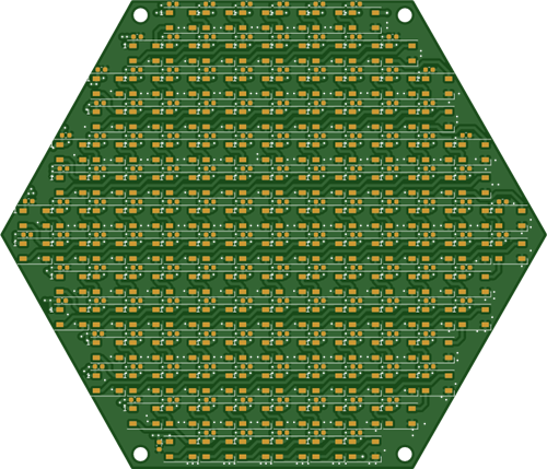
Hi makers!I created a hexagonal PCB with many WS2812B LEDs, 144 in total, for which I thought of pla...
Hexagonal Panel with WS2812B LEDs
Hi makers!I created a hexagonal PCB with many WS2812B LEDs, 144 in total, for which I thought of pla...
-
 ESP01S Minimal Board
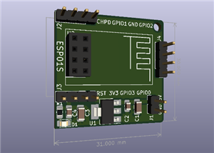
Hi makers!I created this small PCB for ESP01S because before I was using a DIY version and then I bo...
ESP01S Minimal Board
Hi makers!I created this small PCB for ESP01S because before I was using a DIY version and then I bo...
-
 4x4x4 cube with blue LEDs
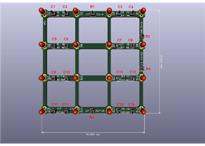
Hi makers!I know that these days there are many variations of LEDs, for example SMDs are smaller and...
4x4x4 cube with blue LEDs
Hi makers!I know that these days there are many variations of LEDs, for example SMDs are smaller and...
-
 Low cost turntable 😁
Hi makers!I'm entering this competition with a small project that I've wanted to make for some time,...
Low cost turntable 😁
Hi makers!I'm entering this competition with a small project that I've wanted to make for some time,...
-
 A DIY charger for 12V battery
Hello everyone!I present to you a project that really didn't reach its final state, until recently. ...
A DIY charger for 12V battery
Hello everyone!I present to you a project that really didn't reach its final state, until recently. ...
-
 ESP01 board
Hello PCBWayers!You probably know that ESP01S/01 boards can be a little difficult to use in an easie...
ESP01 board
Hello PCBWayers!You probably know that ESP01S/01 boards can be a little difficult to use in an easie...
-
 ESP12F Board
Hello makers!Some time ago I had a shopping coupon and I thought about making some simple PCBs with ...
ESP12F Board
Hello makers!Some time ago I had a shopping coupon and I thought about making some simple PCBs with ...
-
SmallOLED - Live PC Stats, Animated Clocks & Audio Visualizer
677 0 3 -
"Talking Multimeter": Arduino-Based Speech Add-on for Multimeters with SCPI Protocol
386 0 1 -
Programmable Mist Maker - XIAO / QT PY Extension
2828 2 3 -
RadioHAT - Raspberry Pi radio development platform
2424 0 4 -
-
-
-
ARPS-2 – Arduino-Compatible Robot Project Shield for Arduino UNO
4510 0 6


















