


|
KiCADKicad
|
4x4x4 cube with blue LEDs
Hi makers!
I know that these days there are many variations of LEDs, for example SMDs are smaller and brighter, there are addressable LEDs, i.e. individually controllable using a microcontroller, but I can't part with TH LEDs so easily so I'm trying to put them in a more favorable light through a different project-design.
Mostly the necessary things used are:
• 64x LEDs, either 3mm or 5mm, the color is your choice;
• 16x 220Ω resistors [TH];
• 2x 2N2222 transistors;
• 4x 10kΩ resistors;
• microcontroller board (e.g. ATMega);
• PCB of course;
• some male/female pin headers;
• 1mm copper rod;
• quite a bit of manual work...and patience.
I used both new and salvaged components that I reuse without any problems.
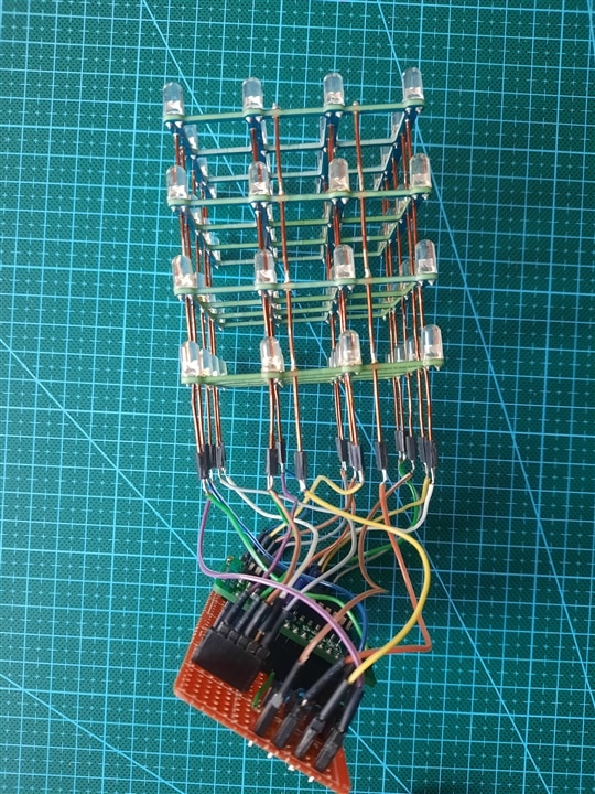
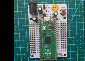
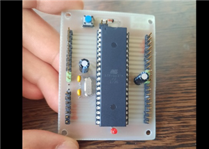
For all these LEDs to be more delightful we need an intelligent control (and the human eye which is easy to fool 😆), the microcontroller I use is an ATMega328P mounted on a minimal PCB that I atached to test board. I had to solder some more components and the conclusion I came to was to use pin headers. Maybe I could have used only the minimal PCB but it only resulted in an unwanted crowding of wires and solders.
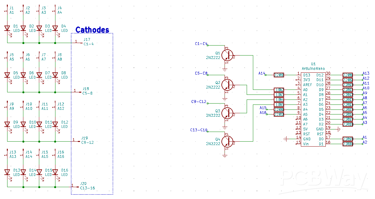
I used almost all available GPIOs, as you can see in the pictures. I placed a 220Ω resistor on each GPIO that is connected to the LEDs anodes and the BJT transistors have their collectors connected to the cathodes, one for each layer.
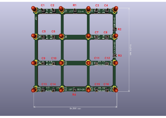
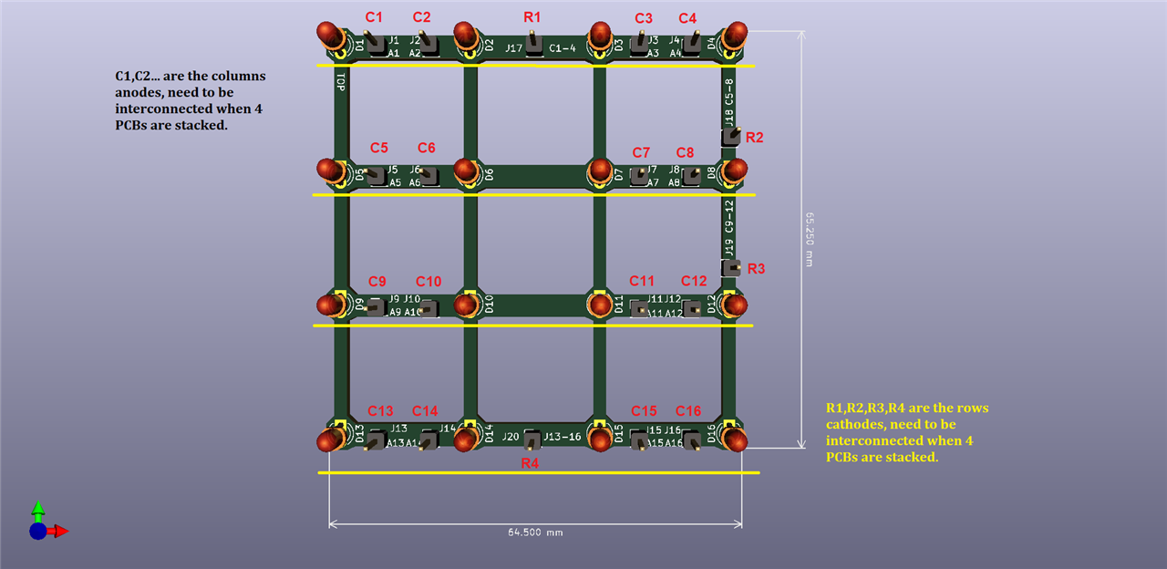
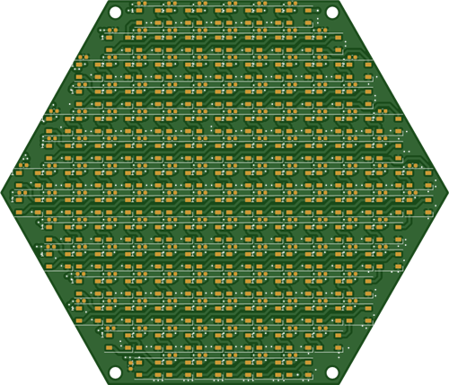
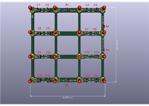
I thought I'd build a PCB for this cube to be more stable, rather than soldering LEDs on a wire, and maybe even positioning them crookedly. So, a simple PCB just for LEDs, precisely cut, dimensions ~65x65mm. We have 16 LEDs on each layer, grouped in 4. The cathodes are interconnected vertically, 4 on each layer.
Circuit:

PCB for LEDs:
Since I made a PCB for the LEDs, another minimal one for the microcontroller, the rest of the resistors and transistors components can be assembled on a test PCB. So I proceeded to a "low cost" PCB, let's say.
This is where the headache starts. Unfortunately, I didn't analyze this project in detail and I missed some aspects. The first would be that the copper wire I use is 1mm in diameter. The holes drilled in the PCB are about the same size, but in the end they fit. Another thing was that the copper wire has a protective outer layer of enamel (or something like that) that is quite difficult to remove but I handled it somwhow. Even so, at some point it was difficult to make correct soldering. I found a coil and cut a few segments with pliers, then removed the outer enamel little by little. One thing I try to apply as often as I can, modular assembly, I first thought about the PCB with LEDs because it is a little difficult to troubleshoot if problems arise, but at least I managed with the 20 wires soldered to the rods, I used female headers.
The layers are spaced ~20mm apart, which is enough for 5mm LEDs.
Tips for anyone who wants to do such a project: use a wire or rod that can be soldered along its entire length (without protective outer layer), it saves you a lot of manual work; position the 4 layers (PCBs) then insert all the wires through the interconnection holes. Later, you can easily space them out as you wish.
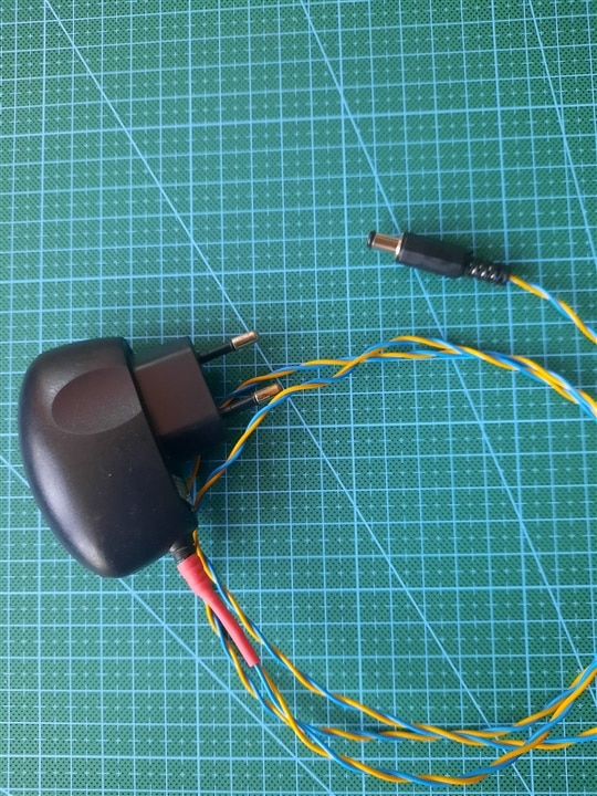
I used a single power supply, 5V, for which I had to solder the wires and the DC jack.
The microcontroller + test board:

Soldering on the test board:
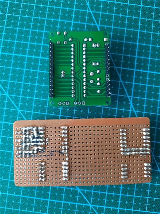
Assembled PCB with LEDs:

Assembled PCB:
Cheap enclosure (made of cardboard):

Enclosure:
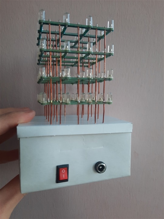
Inside the box:

Get the copper rods:
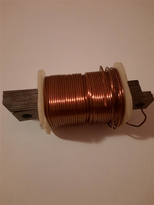
Cut the coper rods:

5V power supply:
Emergency solution, the box is made of cardboard, I definitely won't keep this case, but my friend is on vacation at the moment and I can't call on him to build a proper case on the 3D printer, but he will be available next year (a long time until then 😂😂). It will be useful for me both for the layout and for proper mounting of the boards.
The program takes up almost all available memory, it is not created by me, it is open source, I took it from the internet some time ago. I can't tell you much about this it. Thanks to the author for that. 🙏🙏
And a short video: https://drive.google.com/file/d/1_zM-xJtUpROYN9edPy9M5RC867_Q-HA0/view?usp=sharing
Have a great day! 🙂
4x4x4 cube with blue LEDs
Project images are for reference only. Actual production is based on the manufacturing files on the project page.
Please review the designer's notes (e.g., PCB thickness) and select the appropriate options.
PCBWay is not responsible
for issues caused by unsuitable parameter selections.
For more important ordering information, please refer to
Read More


Raspberry Pi 5 7 Inch Touch Screen IPS 1024x600 HD LCD HDMI-compatible Display for RPI 4B 3B+ OPI 5 AIDA64 PC Secondary Screen(Without Speaker)
BUY NOW

- Comments(0)
- Likes(0)
 More by cris 🙂
-
 Dynamic decoration with LEDs and more
Hello everyone!As you can see in the title, we have a circuit with LEDs, many LEDs, it's a 4x4 LEDs ...
Dynamic decoration with LEDs and more
Hello everyone!As you can see in the title, we have a circuit with LEDs, many LEDs, it's a 4x4 LEDs ...
-
 LEDs Stars
Hello everyone! I'm signing up for this competition with a small project designed to attract your a...
LEDs Stars
Hello everyone! I'm signing up for this competition with a small project designed to attract your a...
-
 Audio amplifier with LM386 (and BASS boost)
Hello everyone!Circuit descriptionThe LM386 is quite a ve...
Audio amplifier with LM386 (and BASS boost)
Audio amplifier with LM386 (and BASS boost)Hello everyone!Circuit descriptionThe LM386 is quite a ve...
-
 Audio amplifier 25W TDA2030
A fairly well-known and interesting montagePresentationThe presented audi...
Audio amplifier 25W TDA2030
Audio amplifier 25W TDA2030A fairly well-known and interesting montagePresentationThe presented audi...
-
 Raspberry Pi Pico Expansion Board
Hello everyone!UPDATE!!!I made some changes, routing in particular, and freed up the board of a few ...
Raspberry Pi Pico Expansion Board
Hello everyone!UPDATE!!!I made some changes, routing in particular, and freed up the board of a few ...
-
 Adjustable voltage power supply
Among the most important electronic devices in the electronics laboratory is the voltage source. Thi...
Adjustable voltage power supply
Among the most important electronic devices in the electronics laboratory is the voltage source. Thi...
-
 Digital Clock with AT89C2051
Circuit OperationShort SW2 presses cycle through displaying the current time in HH:MM and MM:SS form...
Digital Clock with AT89C2051
Circuit OperationShort SW2 presses cycle through displaying the current time in HH:MM and MM:SS form...
-
 Switch based light sensor
Hi!The circuit shown can be used to turn on the light in the garden, or some light panels / advertis...
Switch based light sensor
Hi!The circuit shown can be used to turn on the light in the garden, or some light panels / advertis...
-
 LM3909 flashing indicator
I present to you a circuit which is a little outdated, but quite pleasant for some, I saw that this ...
LM3909 flashing indicator
I present to you a circuit which is a little outdated, but quite pleasant for some, I saw that this ...
-
 Hexagonal Panel with WS2812B LEDs
Hi makers!I created a hexagonal PCB with many WS2812B LEDs, 144 in total, for which I thought of pla...
Hexagonal Panel with WS2812B LEDs
Hi makers!I created a hexagonal PCB with many WS2812B LEDs, 144 in total, for which I thought of pla...
-
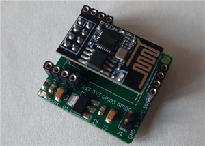
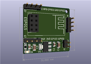 ESP01S Minimal Board
Hi makers!I created this small PCB for ESP01S because before I was using a DIY version and then I bo...
ESP01S Minimal Board
Hi makers!I created this small PCB for ESP01S because before I was using a DIY version and then I bo...
-
 4x4x4 cube with blue LEDs
Hi makers!I know that these days there are many variations of LEDs, for example SMDs are smaller and...
4x4x4 cube with blue LEDs
Hi makers!I know that these days there are many variations of LEDs, for example SMDs are smaller and...
-
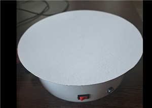 Low cost turntable 😁
Hi makers!I'm entering this competition with a small project that I've wanted to make for some time,...
Low cost turntable 😁
Hi makers!I'm entering this competition with a small project that I've wanted to make for some time,...
-
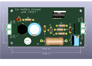 A DIY charger for 12V battery
Hello everyone!I present to you a project that really didn't reach its final state, until recently. ...
A DIY charger for 12V battery
Hello everyone!I present to you a project that really didn't reach its final state, until recently. ...
-
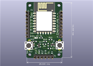
 ESP01 board
Hello PCBWayers!You probably know that ESP01S/01 boards can be a little difficult to use in an easie...
ESP01 board
Hello PCBWayers!You probably know that ESP01S/01 boards can be a little difficult to use in an easie...
-
 ESP12F Board
Hello makers!Some time ago I had a shopping coupon and I thought about making some simple PCBs with ...
ESP12F Board
Hello makers!Some time ago I had a shopping coupon and I thought about making some simple PCBs with ...
-
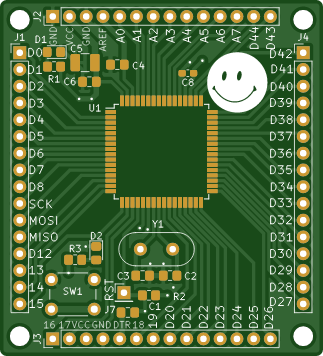
 ATMega32 Board
Hi !I remembered this simple project I made for myself, you can use it with an ATMega32 or ATMega16 ...
ATMega32 Board
Hi !I remembered this simple project I made for myself, you can use it with an ATMega32 or ATMega16 ...
-
 AT90CAN128
Hello makers!Here is a guy who likes to build various, small, electronic circuits, and through this ...
AT90CAN128
Hello makers!Here is a guy who likes to build various, small, electronic circuits, and through this ...
-
Programmable Mist Maker - XIAO / QT PY Extension
1048 2 1 -
RadioHAT - Raspberry Pi radio development platform
846 0 2 -
-
-
-
-
ARPS-2 – Arduino-Compatible Robot Project Shield for Arduino UNO
3314 0 6 -
A Compact Charging Breakout Board For Waveshare ESP32-C3
3916 3 8 -
AI-driven LoRa & LLM-enabled Kiosk & Food Delivery System
4299 2 2


