


|
LA 55-PLEM USA Inc.
|
x 1 | |
|
|
LV 25-PLEM
|
x 1 | |
|
|
Arduino Nano V3 |
x 1 | |
|
|
LM2575SX-5.0/NOPB |
x 1 | |
|
|
LMC6482IMM/NOPBTexas Instruments
|
x 1 | |
|
|
LCD 2X16 |
x 1 |

|
Soldering iron |
|

|
Pliers |
|

|
Tweezers for PCB |
|

|
Soldering Iron Wire |
|

|
KiCADKicad
|
|

|
arduino IDEArduino
|
|

|
Node-Rednodered
|
|
|
|
Simul IDE |
The use of IoT technology for monitoring specific electrical parameters of autonomous power systems
Hello everyone!
A brief introduction of this project.
What you see presented here is a home made (or DIY) project through which I wanted to check the consumption of some electronic devices that work in direct current. I especially wanted the power source that provides energy to be a battery, also because more and more people are starting to use photovoltaic panels, and as you well know, energy is stored in batteries, big batteries. For example, I had at my disposal a 12V battery, not very powerful.
What does consumption mean? That is, the power (voltage x current) consumed over time by an electronic device. These electrical parameters (voltage, current, power) are obtained by measuring with the help of transducers (voltage or current). In this stage of data acquisition, we also used analog electronic circuits. You can find a description in the link below.
The electrical parameters are displayed locally, on a 16x2 LCD. From here things start to become more familiar. How did I display the data? Well, with the help of our friend the Arduino Nano. From the analog circuits used for data acquisition, I took some voltage signals that I connected to the ADC port of the Arduino board. The signals are interpreted, entered into calculation formulas, and thus the Voltage-Current-Power results.
The local display of data is obviously useful, but what would it be like to see these data without being on the spot? Well, that's what I used NodeRed for. I have not worked with such interfaces, it is the first time I use it. I like to make things, I'm not very good at programming, so I opened the internet and started documenting myself as best I could. I did the first tests with NodeRed, as usual, with DHT11 connected to the Arduino and data retrieval in NodeRed. Pretty nice graphic interface, charts, gauges, etc.
After doing these tests, I moved on to my project.
Through NodeRed I was able to access the graphical interface from a distance.
Obviously, I have to mention the fact that everything didn't work out the first time, you ask a friend, you borrow something, it's something normal.
The results of the measurements are quite good, compared to those measured with a DMM for example, I was really pleasantly surprised. I mean, a difference of a few mV or mA was to be expected, I can't say that I had the most precise calibration of the created system, but it is a very positive result.
The use of IoT technology for monitoring specific electrical parameters of autonomous power systems
Table of contents
General elements about electric transducers
Description of the electrical parameters monitoring system
Simulation of electronic scheme
Practical achievements of the system
Data processing unit
System software components
ANNEXES
Introduction
The project aims to carry out some operations to monitor the most important electrical parameters that characterize an autonomous source of power, namely the voltage that this source provides, and the current that is absorbed by a consumer connected to the source terminals. This electronic assembly is addressed to use in the case of power supply that operates in DC, whose electrical, voltage and current parameters vary in time and depend on the power absorbed by the consumer, which is why it has been opted for studying on an autonomous power source. Meeting some electronic and home appliances, electric vehicles. The rechargeable battery is probably the most popular source of autonomous power. This energy source has made it possible to move from the dependence on the power supply of electronics and other devices of this kind, to portability, namely mobile phones, laptops, electric machines.
This is a sketch, more information can be found in the documentation attached below accessing the link to my drive. I could not upload these files here on the site.
https://drive.google.com/drive/folders/1yb-0X00C4WSuacLhXJ_IriCPPJSw3lnW?usp=sharing
You will be able to access both the software part with codes, and the hardware part with electronic schematics and gerbers files for those interested in the modules. Numerous pictures are available that capture the different stages in which this project was.
Almost all the electronic circuits were made with local resources, so there are not too many electronic components were bought, I applied the "recover-reuse" method. But, if you follow the electronic diagrams, you will easily identify the electronic components. It is not easy for me to buy components from outside the country, in general the costs of purchases from outside the country are not justified here.
It's good that we have a computer and programs for designing, creating documentation, schemes, etc. It really helps us. Of course, there was also manual work, and this should not be forgotten, such as when preparing a base plate (drills, mounting screws); mounting submodules; soldering components on PCBs; there are also enough wires, shorter or longer. Maybe sometimes you don't have everything you need to work, so you borrow tools from a friend, like a drill machine. But all these are part of home made projects. The working time was several weeks, but working on a personal basis, I don't consider it as lost time.
Non-Commercial purpose, informational only.
Thank you and don't forget to press the "Like" button if you think so ! 🤓

The use of IoT technology for monitoring specific electrical parameters of autonomous power systems
*PCBWay community is a sharing platform. We are not responsible for any design issues and parameter issues (board thickness, surface finish, etc.) you choose.


Raspberry Pi 5 7 Inch Touch Screen IPS 1024x600 HD LCD HDMI-compatible Display for RPI 4B 3B+ OPI 5 AIDA64 PC Secondary Screen(Without Speaker)
BUY NOW


- Comments(5)
- Likes(6)
- 2 USER VOTES
- YOUR VOTE 0.00 0.00

-
8design
-
7usability
-
8creativity
-
5content

-
8design
-
7usability
-
8creativity
-
7content
 More by cris 🙂
-
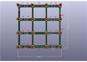
 Dynamic decoration with LEDs and more
Hello everyone!As you can see in the title, we have a circuit with LEDs, many LEDs, it's a 4x4 LEDs ...
Dynamic decoration with LEDs and more
Hello everyone!As you can see in the title, we have a circuit with LEDs, many LEDs, it's a 4x4 LEDs ...
-
 LEDs Stars
Hello everyone! I'm signing up for this competition with a small project designed to attract your a...
LEDs Stars
Hello everyone! I'm signing up for this competition with a small project designed to attract your a...
-
 Audio amplifier with LM386 (and BASS boost)
Hello everyone!Circuit descriptionThe LM386 is quite a ve...
Audio amplifier with LM386 (and BASS boost)
Audio amplifier with LM386 (and BASS boost)Hello everyone!Circuit descriptionThe LM386 is quite a ve...
-
 Audio amplifier 25W TDA2030
A fairly well-known and interesting montagePresentationThe presented audi...
Audio amplifier 25W TDA2030
Audio amplifier 25W TDA2030A fairly well-known and interesting montagePresentationThe presented audi...
-
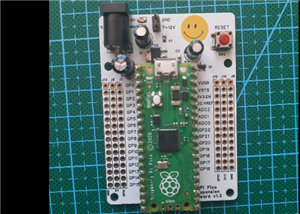 Raspberry Pi Pico Expansion Board
Hello everyone!UPDATE!!!I made some changes, routing in particular, and freed up the board of a few ...
Raspberry Pi Pico Expansion Board
Hello everyone!UPDATE!!!I made some changes, routing in particular, and freed up the board of a few ...
-
 Adjustable voltage power supply
Among the most important electronic devices in the electronics laboratory is the voltage source. Thi...
Adjustable voltage power supply
Among the most important electronic devices in the electronics laboratory is the voltage source. Thi...
-
 Digital Clock with AT89C2051
Circuit OperationShort SW2 presses cycle through displaying the current time in HH:MM and MM:SS form...
Digital Clock with AT89C2051
Circuit OperationShort SW2 presses cycle through displaying the current time in HH:MM and MM:SS form...
-
 Switch based light sensor
Hi!The circuit shown can be used to turn on the light in the garden, or some light panels / advertis...
Switch based light sensor
Hi!The circuit shown can be used to turn on the light in the garden, or some light panels / advertis...
-
 LM3909 flashing indicator
I present to you a circuit which is a little outdated, but quite pleasant for some, I saw that this ...
LM3909 flashing indicator
I present to you a circuit which is a little outdated, but quite pleasant for some, I saw that this ...
-
 4x4x4 cube with blue LEDs
Hi makers!I know that these days there are many variations of LEDs, for example SMDs are smaller and...
4x4x4 cube with blue LEDs
Hi makers!I know that these days there are many variations of LEDs, for example SMDs are smaller and...
-
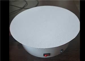 Low cost turntable 😁
Hi makers!I'm entering this competition with a small project that I've wanted to make for some time,...
Low cost turntable 😁
Hi makers!I'm entering this competition with a small project that I've wanted to make for some time,...
-
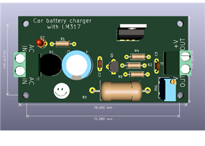 A DIY charger for 12V battery
Hello everyone!I present to you a project that really didn't reach its final state, until recently. ...
A DIY charger for 12V battery
Hello everyone!I present to you a project that really didn't reach its final state, until recently. ...
-
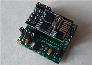 ESP01 board
Hello PCBWayers!You probably know that ESP01S/01 boards can be a little difficult to use in an easie...
ESP01 board
Hello PCBWayers!You probably know that ESP01S/01 boards can be a little difficult to use in an easie...
-
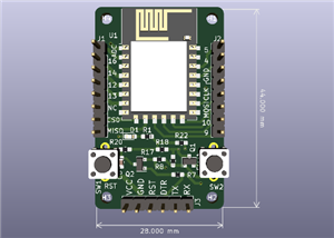 ESP12F Board
Hello makers!Some time ago I had a shopping coupon and I thought about making some simple PCBs with ...
ESP12F Board
Hello makers!Some time ago I had a shopping coupon and I thought about making some simple PCBs with ...
-
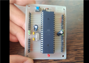 ATMega32 Board
Hi !I remembered this simple project I made for myself, you can use it with an ATMega32 or ATMega16 ...
ATMega32 Board
Hi !I remembered this simple project I made for myself, you can use it with an ATMega32 or ATMega16 ...
-
 AT90CAN128
Hello makers!Here is a guy who likes to build various, small, electronic circuits, and through this ...
AT90CAN128
Hello makers!Here is a guy who likes to build various, small, electronic circuits, and through this ...
-
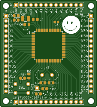
 PCBWay 11th Badge Design
Hello PCBwayers!I'm here to participate in the PCBWay 11th Badge Design Contest and after a few idea...
PCBWay 11th Badge Design
Hello PCBwayers!I'm here to participate in the PCBWay 11th Badge Design Contest and after a few idea...
-
 The use of IoT technology for monitoring specific electrical parameters of autonomous power systems
Hello everyone!A brief introduction of this project.What you see presented here is a home made (or D...
The use of IoT technology for monitoring specific electrical parameters of autonomous power systems
Hello everyone!A brief introduction of this project.What you see presented here is a home made (or D...
-
-
ARPS-2 – Arduino-Compatible Robot Project Shield for Arduino UNO
1370 0 5 -
A Compact Charging Breakout Board For Waveshare ESP32-C3
1897 3 7 -
AI-driven LoRa & LLM-enabled Kiosk & Food Delivery System
1901 2 0 -
-
-
-
ESP32-C3 BLE Keyboard - Battery Powered with USB-C Charging
2077 0 1 -


