


|
KiCADKicad
|
Differential voltage source
Circuit working principle
The application schemes of the already integrated classics LM317 and LM337 are used, but with the modified reference to increase the voltage from 0V. The power supply is made from a 24VA transformer that can provide 2x18V at 1.5A. The voltage is adjusted from the two potentiometers when used as a service source. Therefore, the LM317 and LM337 are part of the series of voltage regulators adjustable in the range of 1.25 V to 37 V at a current of 1.5A. The LM317 is designed as a positive voltage regulator and the LM337 is designed as a negative voltage regulator. These include a current limiting circuit, thermal overload protection and protection for safe operation.
The classic application of the LM317 controller is the one in the figure below:

The voltage at the output of the regulator is calculated by the formula:

The C5 capacitor is used for the rejection of transient signals from the output, the oscillations that would occur are integrated by this capacity. If it is used, the D9 diode is inserted, which turns the tips on the output line. Overload protection is very effective even when the V control terminal is detached. We therefore have extreme security. We have only one impediment to the classic scheme: the output voltage is not regulated from 0V precisely due to the voltage that falls on the two sets of the internal regulating transistors. The solution would be to lower the reference voltage by 1.25V, ie to compensate for the voltage that appears on the two junctions. This solution is applied in the figure below.

In this case, the voltage at the output of the regulator is calculated with the formula:

Given that the LM337 is identical to the LM317 as an internal structure, but designed for negative voltage, both the schematics and the calculation relations are valid:

80dB rejection is provided by C11 and C12. The source is protected with a 32mA fuse and the presence of the output voltage is indicated by LEDs D2 and D3 on the two sections. Diodes D8 and D9 have the role of protecting the regulators at reverse voltage applied to the output, in case we supply reactive loads.

Differential voltage source
*PCBWay community is a sharing platform. We are not responsible for any design issues and parameter issues (board thickness, surface finish, etc.) you choose.


Raspberry Pi 5 7 Inch Touch Screen IPS 1024x600 HD LCD HDMI-compatible Display for RPI 4B 3B+ OPI 5 AIDA64 PC Secondary Screen(Without Speaker)
BUY NOW


- Comments(0)
- Likes(1)
 More by cris 🙂
-
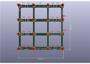
 Dynamic decoration with LEDs and more
Hello everyone!As you can see in the title, we have a circuit with LEDs, many LEDs, it's a 4x4 LEDs ...
Dynamic decoration with LEDs and more
Hello everyone!As you can see in the title, we have a circuit with LEDs, many LEDs, it's a 4x4 LEDs ...
-
 LEDs Stars
Hello everyone! I'm signing up for this competition with a small project designed to attract your a...
LEDs Stars
Hello everyone! I'm signing up for this competition with a small project designed to attract your a...
-
 Audio amplifier with LM386 (and BASS boost)
Hello everyone!Circuit descriptionThe LM386 is quite a ve...
Audio amplifier with LM386 (and BASS boost)
Audio amplifier with LM386 (and BASS boost)Hello everyone!Circuit descriptionThe LM386 is quite a ve...
-
 Audio amplifier 25W TDA2030
A fairly well-known and interesting montagePresentationThe presented audi...
Audio amplifier 25W TDA2030
Audio amplifier 25W TDA2030A fairly well-known and interesting montagePresentationThe presented audi...
-
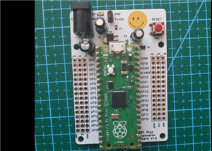 Raspberry Pi Pico Expansion Board
Hello everyone!UPDATE!!!I made some changes, routing in particular, and freed up the board of a few ...
Raspberry Pi Pico Expansion Board
Hello everyone!UPDATE!!!I made some changes, routing in particular, and freed up the board of a few ...
-
 Adjustable voltage power supply
Among the most important electronic devices in the electronics laboratory is the voltage source. Thi...
Adjustable voltage power supply
Among the most important electronic devices in the electronics laboratory is the voltage source. Thi...
-
 Digital Clock with AT89C2051
Circuit OperationShort SW2 presses cycle through displaying the current time in HH:MM and MM:SS form...
Digital Clock with AT89C2051
Circuit OperationShort SW2 presses cycle through displaying the current time in HH:MM and MM:SS form...
-
 Switch based light sensor
Hi!The circuit shown can be used to turn on the light in the garden, or some light panels / advertis...
Switch based light sensor
Hi!The circuit shown can be used to turn on the light in the garden, or some light panels / advertis...
-
 LM3909 flashing indicator
I present to you a circuit which is a little outdated, but quite pleasant for some, I saw that this ...
LM3909 flashing indicator
I present to you a circuit which is a little outdated, but quite pleasant for some, I saw that this ...
-
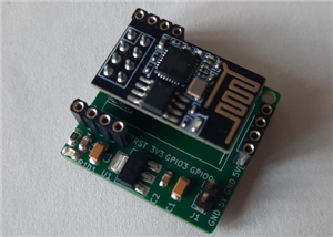
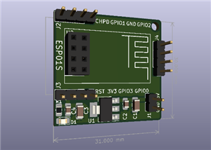 ESP01S Minimal Board
Hi makers!I created this small PCB for ESP01S because before I was using a DIY version and then I bo...
ESP01S Minimal Board
Hi makers!I created this small PCB for ESP01S because before I was using a DIY version and then I bo...
-
 4x4x4 cube with blue LEDs
Hi makers!I know that these days there are many variations of LEDs, for example SMDs are smaller and...
4x4x4 cube with blue LEDs
Hi makers!I know that these days there are many variations of LEDs, for example SMDs are smaller and...
-
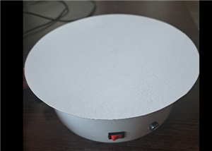 Low cost turntable 😁
Hi makers!I'm entering this competition with a small project that I've wanted to make for some time,...
Low cost turntable 😁
Hi makers!I'm entering this competition with a small project that I've wanted to make for some time,...
-
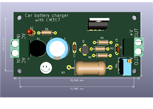 A DIY charger for 12V battery
Hello everyone!I present to you a project that really didn't reach its final state, until recently. ...
A DIY charger for 12V battery
Hello everyone!I present to you a project that really didn't reach its final state, until recently. ...
-
 ESP01 board
Hello PCBWayers!You probably know that ESP01S/01 boards can be a little difficult to use in an easie...
ESP01 board
Hello PCBWayers!You probably know that ESP01S/01 boards can be a little difficult to use in an easie...
-
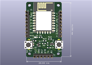 ESP12F Board
Hello makers!Some time ago I had a shopping coupon and I thought about making some simple PCBs with ...
ESP12F Board
Hello makers!Some time ago I had a shopping coupon and I thought about making some simple PCBs with ...
-
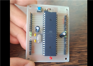 ATMega32 Board
Hi !I remembered this simple project I made for myself, you can use it with an ATMega32 or ATMega16 ...
ATMega32 Board
Hi !I remembered this simple project I made for myself, you can use it with an ATMega32 or ATMega16 ...
-
 AT90CAN128
Hello makers!Here is a guy who likes to build various, small, electronic circuits, and through this ...
AT90CAN128
Hello makers!Here is a guy who likes to build various, small, electronic circuits, and through this ...
-
 PCBWay 11th Badge Design
Hello PCBwayers!I'm here to participate in the PCBWay 11th Badge Design Contest and after a few idea...
PCBWay 11th Badge Design
Hello PCBwayers!I'm here to participate in the PCBWay 11th Badge Design Contest and after a few idea...
-
Programmable Mist Maker - XIAO / QT PY Extension
172 0 0 -
RadioHAT - Raspberry Pi radio development platform
182 0 1 -
-
-
-
-
ARPS-2 – Arduino-Compatible Robot Project Shield for Arduino UNO
2767 0 5 -
A Compact Charging Breakout Board For Waveshare ESP32-C3
3275 3 8 -
AI-driven LoRa & LLM-enabled Kiosk & Food Delivery System
3530 2 2


