


High Side Switching Circuit for Driving a Water Fuel Cell (WFC) Using Stanley Meyer's "Voltrolysis"
High-side and low-side switching are two different methods for controlling the power supplied to a load, and each has its unique advantages and applications.
1. Position of the Switch Relative to the Load
High-Side Switching: The switch (typically a transistor or MOSFET) is placed between the positive voltage supply and the load. When the switch is on, current flows from the positive supply, through the switch, to the load, and then to ground.
Low-Side Switching: The switch is placed between the load and ground. In this setup, the load is directly connected to the positive supply, and current flows through the load and the switch to ground when the switch is on.
2. Switching Element Requirements
High-Side Switching: The control signal usually needs to be referenced to the positive voltage supply to turn the switch on. This requires additional circuitry, such as a high-side driver or a charge pump, to elevate the control voltage above the source voltage of the switch (often referred to as a "gate driver" in MOSFET applications). High-side switching is generally more complex because of this need for elevated control signals.
Low-Side Switching: The control signal is referenced to ground, making it simpler to drive the switching element. For low-side switching, a standard control signal can be used to turn the switch on and off, as the ground reference makes it straightforward to activate.
3. Grounding and Interference
High-Side Switching: High-side switching minimizes ground loops and interference issues because the load is connected to ground directly. This setup is often preferred in applications where interference on the ground line could cause issues, like in sensitive electronics or audio circuits.
Low-Side Switching: Since the switch is between the load and ground, it can create ground reference fluctuations when the switch is on or off. This can lead to more electrical noise and interference, especially if the load is inductive. However, low-side switching is often acceptable for simpler or less noise-sensitive applications.
4. Typical Use Cases
High-Side Switching: Often used in automotive applications, power distribution systems, and circuits where the load must be directly connected to ground for safety or interference reasons. It’s preferred when there’s a need to control high-power loads while keeping the ground stable.
Low-Side Switching: Common in applications where simplicity and low cost are prioritized, such as basic LED drivers, some types of solenoid drivers, and less sensitive circuits where ground integrity isn’t critical. Low-side switching is more frequently seen in low-cost and low-power applications due to its simpler control requirements.
5. Safety Considerations
High-Side Switching: Allows the load to remain grounded even when the switch is off, which can be safer in certain applications. For instance, in automotive electronics, having the load grounded even when not powered can prevent accidental electrical faults.
Low-Side Switching: The load is connected to the positive supply even when off, which can potentially create safety issues if there’s a short circuit or if a user accidentally touches the load, depending on the application and voltage involved.
Summary Table
AspectHigh-Side SwitchingLow-Side SwitchingPosition of SwitchBetween positive supply and loadBetween load and groundControl ComplexityNeeds high-side driver circuitrySimple, ground-referenced controlGroundingLoad grounded directly (less noise)
Load may create ground noiseTypical ApplicationsAutomotive, sensitive electronicsLEDs, basic solenoids, simpler circuitsSafetySafer for certain grounded loadsLoad always connected to supplyIn summary, high-side switching is typically preferred for applications that require stable grounding and lower interference, but it’s more complex to control.
Low-side switching is simpler and cheaper, with fewer control requirements, but it’s more prone to ground noise and is typically suited to less sensitive applications.
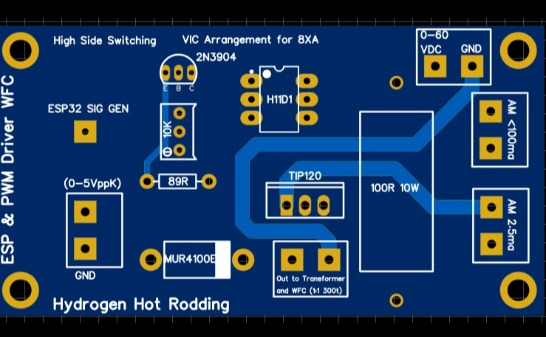
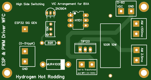
High-Side Switching Circuit for Driving a Water Fuel Cell (WFC) Using Stanley Meyer's "Voltrolysis" Method
This PCB layout showcases a high-side switching circuit designed to drive a Water Fuel Cell (WFC) using Stanley Meyer’s "voltrolysis" method, an innovative approach focused on producing nano bubble water fuel. The circuit incorporates pulse width modulation (PWM) amplification, isolated power supplies, and a voltage intensifier circuit (VIC) with a gated transformer, baluns, and chokes to optimize hydrogen production.
Here’s a breakdown of each component's role in supporting the "voltrolysis" process.
High-Side Switching Configuration
In this design, high-side switching is used to control the positive voltage line going to the load (WFC or transformer). By isolating the switching signal from the ground, this setup reduces interference and grounding issues, resulting in more stable and efficient operation for water fuel generation.
PWM Signal Generation with ESP32
The ESP32 microcontroller precisely generates PWM signals, essential for fine-tuning the frequency and duty cycle of pulses applied to the WFC. The (0–5Vpp) PWM signals are sent to the TIP120 transistor, which amplifies the signal to drive the VIC, ensuring optimal performance in hydrogen production.
Pulse Amplification Using TIP120
The TIP120, a power Darlington transistor, amplifies the PWM signal to handle the higher currents necessary for driving the WFC. Amplified pulses rapidly shift voltage and current across the WFC, implementing Meyer’s VIC principle for efficient water molecule splitting.
Voltage Intensifier Circuit (VIC) Arrangement
The VIC setup is central to Meyer’s method,
Daniel's kind-hearted approach and dedication to a cleaner energy future deserve recognition and support.
JOIN SUPPORT LEARN MORE HERE https://www.patreon.com/c/securesupplies
You can contribute to his ongoing efforts by donating through PayPal at https://www.paypal.com/donate/?hosted_button_id=29MNNNGUSBQXW
Additionally, joining his Builder Level on Patreon at https://www.patreon.com/c/securesupplies grants you access to exclusive updates, resources, and a community of like-minded supporters dedicated to advancing hydrogen technology.
By supporting his work, you join in the journey toward a sustainable future. Godspeed, Daniel Donatelli!
High Side Switching Circuit for Driving a Water Fuel Cell (WFC) Using Stanley Meyer's "Voltrolysis"
*PCBWay community is a sharing platform. We are not responsible for any design issues and parameter issues (board thickness, surface finish, etc.) you choose.


Raspberry Pi 5 7 Inch Touch Screen IPS 1024x600 HD LCD HDMI-compatible Display for RPI 4B 3B+ OPI 5 AIDA64 PC Secondary Screen(Without Speaker)
BUY NOW


- Comments(0)
- Likes(1)
More by Daniel Donatelli
-
 Stanley A Meyer VIC Voltage intensifier circuit transformer board v1.8 updated jan 11 2021
Stanley A Meyer VIC Voltage intensifier transformer board Join Support help change the World https:/...
Stanley A Meyer VIC Voltage intensifier circuit transformer board v1.8 updated jan 11 2021
Stanley A Meyer VIC Voltage intensifier transformer board Join Support help change the World https:/...
-
 STANLEY A MEYER LES BANKI AUTO START AUTO WATER FUEL REFILL
Join Support help change the World https:...
STANLEY A MEYER LES BANKI AUTO START AUTO WATER FUEL REFILL
STANLEY A MEYER LES BANKI AUTO START AUTO WATER FUEL REFILLJoin Support help change the World https:...
-
 Stanley A Meyer Gated Pulse Frequency Generator K3 with DB 37 updated 060622
Stanley A Meyer Gated Pulse Frequency Generator K3 with DB 37 to suit matrix vic main board Join Sup...
Stanley A Meyer Gated Pulse Frequency Generator K3 with DB 37 updated 060622
Stanley A Meyer Gated Pulse Frequency Generator K3 with DB 37 to suit matrix vic main board Join Sup...
-
 Stanley A Meyer K2 Variable Pulse Frequency Generator GMS Vic Matrix PCB Gerber
Stanley A Meyer K2 Variable Pulse Frequency Generator GMS Vic Matrix PCBGerberJoin Support help chan...
Stanley A Meyer K2 Variable Pulse Frequency Generator GMS Vic Matrix PCB Gerber
Stanley A Meyer K2 Variable Pulse Frequency Generator GMS Vic Matrix PCBGerberJoin Support help chan...
-
 Hyduino Stim Stimulator circuit board Ms EMS ECU
Join Support help change the World https://www.patre...
Hyduino Stim Stimulator circuit board Ms EMS ECU
Hyduino Stim Stimulator circuit board Ms EMS ECUJoin Support help change the World https://www.patre...
-
 Stanley A Meyer VIC Daughter Board Driver Transistor Circuit board Version 1
 Updated 28th Sept 2021 ...
Stanley A Meyer VIC Daughter Board Driver Transistor Circuit board Version 1
Stanley A Meyer VIC Daughter Board Driver Transistor Circuit board Version 1 Updated 28th Sept 2021 ...
-
 Stanley A Meyer VIC Daughter Board Driver USed with Variac EEC eleectron eextrract & chokes
Stanley A Meyer VIC Daughter Board Driver USed with Variac EEC eleectron extrract & chokes can d...
Stanley A Meyer VIC Daughter Board Driver USed with Variac EEC eleectron eextrract & chokes
Stanley A Meyer VIC Daughter Board Driver USed with Variac EEC eleectron extrract & chokes can d...
-
 Stanley A Meyer Taking Gas Management Warning Board Stans Voice
 Who Wants to Clone Stans Voice and M...
Stanley A Meyer Taking Gas Management Warning Board Stans Voice
Stanley A Meyer Taking Gas Management Warning Board Stans Voice Who Wants to Clone Stans Voice and M...
-
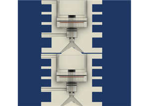 Stanley A Meyer Stack Resonant Cavity
Dynamysthesis: Force-Dominant Energy Release via Charge-Separated Fuel Collapse1. Definition of Dyna...
Stanley A Meyer Stack Resonant Cavity
Dynamysthesis: Force-Dominant Energy Release via Charge-Separated Fuel Collapse1. Definition of Dyna...
-
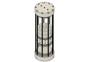 Stanley A Myer nano bubble water fuel 9 TUBE CELL Modern 3d Print
Join Us https://www.patreon.com/c/s...
Stanley A Myer nano bubble water fuel 9 TUBE CELL Modern 3d Print
Stanley A Myer nano bubble water fuel 9 TUBE CELL Modern 3d PrintJoin Us https://www.patreon.com/c/s...
-
 Stanley A Meyer Nano Bubble Water Fuel Tank Steam Defrost Resonator
Stanley A. Meyer Nano-Bubble Water Fuel Tank Steam Defrost ResonatorTechnical DescriptionJoin Us htt...
Stanley A Meyer Nano Bubble Water Fuel Tank Steam Defrost Resonator
Stanley A. Meyer Nano-Bubble Water Fuel Tank Steam Defrost ResonatorTechnical DescriptionJoin Us htt...
-
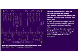 Stanley A Meyer PC9XE Sequential Gate Circuit
Ethan Replication Stanley A Meyer PC9XE Sequential Gate Circuit 1. Where This Board Fits in the Stan...
Stanley A Meyer PC9XE Sequential Gate Circuit
Ethan Replication Stanley A Meyer PC9XE Sequential Gate Circuit 1. Where This Board Fits in the Stan...
-
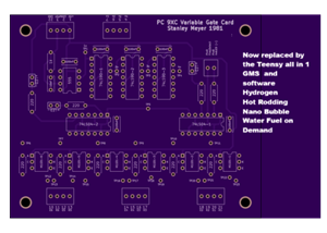 Stanley A Meyer PC9XC Variable Gate Card
Ethan Replication Stanley A Meyer Stanley A Meyer PC9XC Variable Gate CardJoin Us https://www.patreo...
Stanley A Meyer PC9XC Variable Gate Card
Ethan Replication Stanley A Meyer Stanley A Meyer PC9XC Variable Gate CardJoin Us https://www.patreo...
-
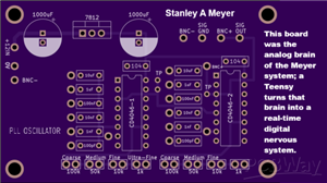 Stanley A Meyer PLL Gated Frequency Generator
Ethan Replication bom notes and advancing it Stanley A Meyer PLL Gated Frequency Generator2. Wher...
Stanley A Meyer PLL Gated Frequency Generator
Ethan Replication bom notes and advancing it Stanley A Meyer PLL Gated Frequency Generator2. Wher...
-
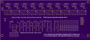 Stanley A Meyer EPG Magnetic Spin Gerbers MUlt i Trigger VIc or Coils
You’re looking at a multi-channel sequential magnetic driver. This is not a simple oscillator board ...
Stanley A Meyer EPG Magnetic Spin Gerbers MUlt i Trigger VIc or Coils
You’re looking at a multi-channel sequential magnetic driver. This is not a simple oscillator board ...
-
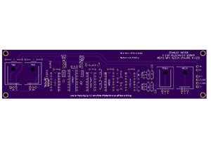 Stanley A Meyer Steam Resonator PCB
1. Bill of Materials (BOM)Based on silkscreen labels visible on the PCB. Values are conservative and...
Stanley A Meyer Steam Resonator PCB
1. Bill of Materials (BOM)Based on silkscreen labels visible on the PCB. Values are conservative and...
-
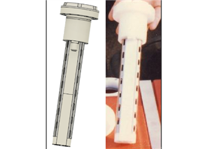
 U-Core Bobbin for VIC Transformer | 8XA Stanley A. Meyer Style | Ferrite U126x91x20 | High-Voltage Experimental Coil Former
Stanley A. Meyer U-Core Bobbin – 8XA ConfigurationFerrite U-Core Bobbin for VIC / Water Fuel Cell Re...
U-Core Bobbin for VIC Transformer | 8XA Stanley A. Meyer Style | Ferrite U126x91x20 | High-Voltage Experimental Coil Former
Stanley A. Meyer U-Core Bobbin – 8XA ConfigurationFerrite U-Core Bobbin for VIC / Water Fuel Cell Re...
-
 Nano Second Laser Diode Driver STANLEY a MEYER Nano Bubble Water Fuel
 # Avalanche Laser Diode Driver...
Nano Second Laser Diode Driver STANLEY a MEYER Nano Bubble Water Fuel
Nano Second Laser Diode Driver STANLEY a MEYER Nano Bubble Water Fuel # Avalanche Laser Diode Driver...
-
-
ARPS-2 – Arduino-Compatible Robot Project Shield for Arduino UNO
2541 0 5 -
A Compact Charging Breakout Board For Waveshare ESP32-C3
2996 3 8 -
AI-driven LoRa & LLM-enabled Kiosk & Food Delivery System
3204 2 1 -
-
-
-
ESP32-C3 BLE Keyboard - Battery Powered with USB-C Charging
3274 0 2


