


ESP32-S3 3 x ADXL357 acquisition board
Specification
My son wanted a high accuracy accelerometer board to characterize a vibrating pot.
Here is an accurate (but still cheap) measurement board.
Specifications are :
- 3 x 3 axis accelerometers 20bits accuracy
- +-10g acceleration range
- 3 sensors fully synchronized
- high rate of acquisition (up to 4kHz. Target 2kHz)
- interfaced with PC via USB
Critical point of this specification is the requirement for synchronization of the 3 sensors. This forbids cheap accelerometers such as MPU6050...
The selected chip was thus ADXL357.
It exposes SYNC signal to trigger acquisition on several chips in parallel and can be intercaed with MPU with highspeed SPI bus.
Here are its main features :
- 0 g offset vs. temperatures (all axes): 0.75mg/°C maximum
- Ultralow noise spectral density (all axes): 75 µg/√Hz
- ADXL356 has user adjustable analog output bandwidth
- ADXL357/ADXL357B digital output features
- Digital SPI and limited I2C interfaces supported
- 20-bit ADC
- Data interpolation routine for synchronous sampling
- Programmable high- and low-pass digital filters
it also offers
- Integrated temperature sensor
- Voltage range options
- VSUPPLY with integral regulators: 2.25 V to 3.6 V
- V1P8ANA, V1P8DIG with internal LDO regulator bypassed: 1.8 V typical ± 10>#/li###
- Operating temperature range: -40°C to +125°C
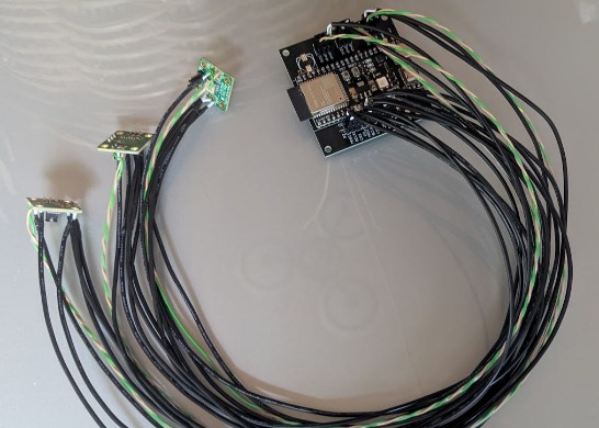
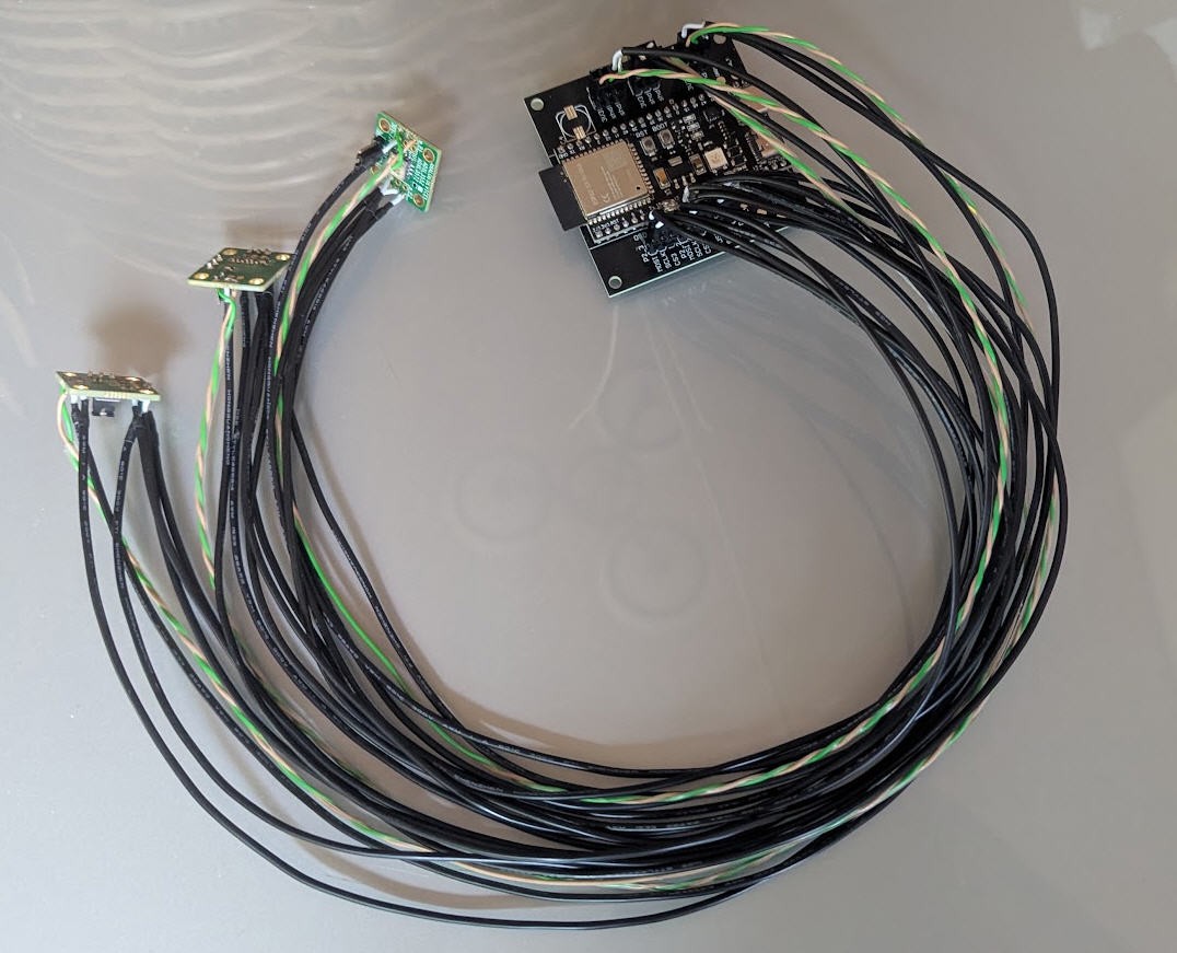
Analog Device sells evaluations boards which are perfect to be integrated on the vibrating pot. We needed 50cm wires in "star configuration" from the ESP32 to the 3 sensors fixed on the pot.
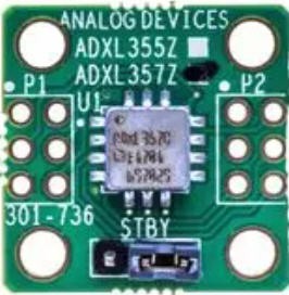
Full specification of this board is here
Note that Synchronized measurement is achievable only with EVAL-ADXL357Z board. The ADXL357 chip has a hardware SYNC pin which is exposed on this eval board.
The SPI bus allows to sustain the high rate of acquisition :
Reading one ADXL357 sample means 3 axes × 20 bits, packed in 9 data bytes, plus an address byte — call it ~10 bytes per sensor. At 2 kHz × 4 sensors, that's 80 kB/s of payload on the bus, or ~640 kbit/s plus transaction overhead (CS toggling, register addressing). The ADXL357 accepts SPI clocks up to 10 MHz; even running conservatively at 4–5 MHz for cable-robustness , each read cycle of all 4 sensors takes roughly 100–150 µs. Sample period at 2 kHz is 500 µs, so the bus is busy well under a third of the time.
ESP32-S3 MPU
USB link. The spec's frame is ~38 bytes (magic + 32-bit counter + 4×3 packed 20-bit axes + CRC16) × 2 kHz ≈ 76 kB/s — well under the spec's own 200 kB/s ceiling, and the ESP32-S3's native USB CDC sustains around 1 MB/s in practice. Order of magnitude of headroom.
CPU. The S3 runs dual-core at 240 MHz. At 2 kHz we have 500 µs per cycle; the SPI reads plus packing plus CRC take a fraction of that in C/C++. The dual core is used in standard pattern — one core handles the SYNC timer ISR and SPI reads into a ring buffer, the other drains the buffer to USB — makes losing frames genuinely hard.
Schematics
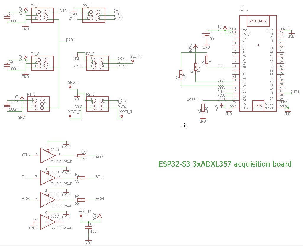
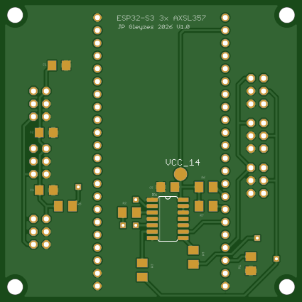
Apart from the ESP32-S3 and the connectors for the 3 ADXL537, this schematics shows a buffer 74LVC125AD. This buffer (Low Voltage version) will clean up the high freqency signals DRDY, SCLK, MOSI produced by the ESP32-S3 and routed to the sensors via shielded wires.
PCB
The PCB was designed with Eagle software.
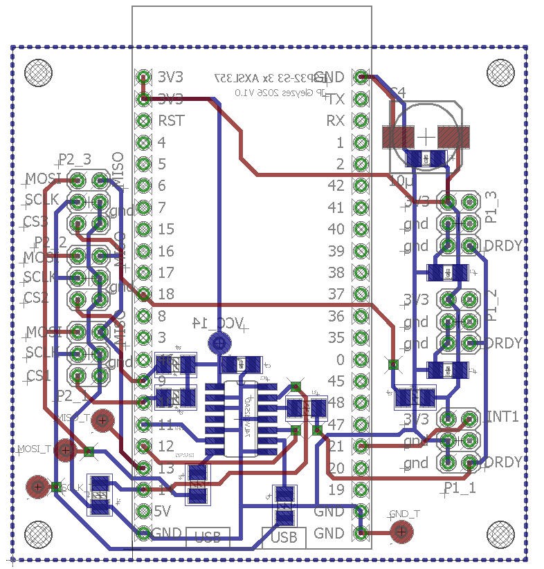
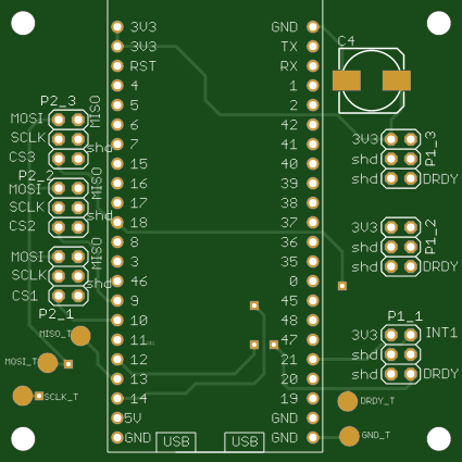
The ESP32 goes on the top side, while all the other components go to the bottom side.
PCB can be bought at PCBWay directly from this project page
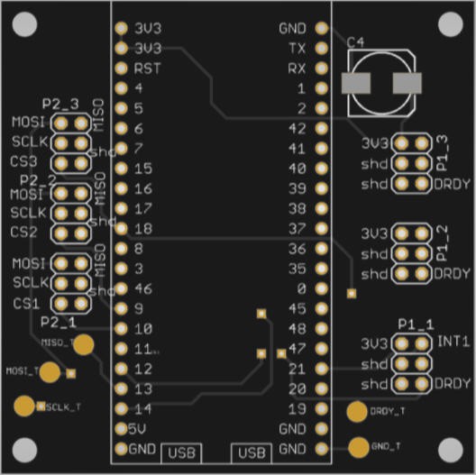
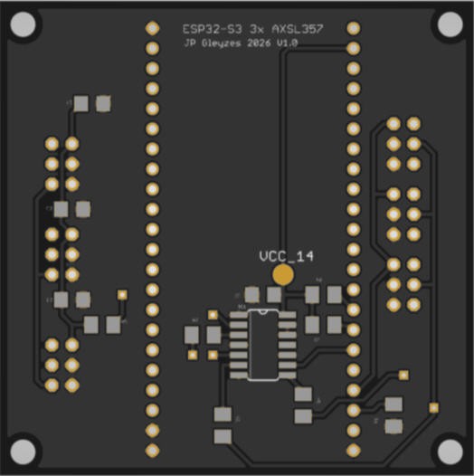
The PCB was kindly sponsored by PCBWay and is as usual of excellent quality.

and if you are new to PCBWay please use this affiliated link : https://pcbway.com/g/o35z4O
soldering should be easy but special care is needed for shielded cables.
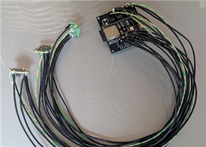
Use single core shielded cable for MOSI, MISO, SCLK, CS and DRDY. The core is soldered of the Eval board and on the ESP32 side.
the shield is only soldered on the ESP32 side (pins labeled shd)
note also that connectors P1 on eval board side must be shorted between pins 1 and 3
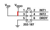
This is needed to connect VDDIO and VDD. On ESP32 side only VDDIO is connected to 3.3V
note also that INT2 is left unsoldered on sensor side.
INT1 is only soldered for sensor1 it will tell the ESP32 (via interrupt) that acquisition is finished for this sensor. And as all sensors are synchronized a single interrupt is enough for all of them. (edit: for the moment INT signal is unused and the board works fine !)
Soldering was easy excepted the wires... not too difficult but very long ! Here is the result
Firmware
Source code is available on my github pages here
The code is quite easy to follow.
This version synchronises the acquisitions of the three sensors but does not (yet) use interrupt signal to fetch the values.
Instead it polls at 2000 kHz the internal fifo buffer of the sensors. It then outputs the decoded values on the USB port of the ESP32-S3 (on my board it's the left bottom port).
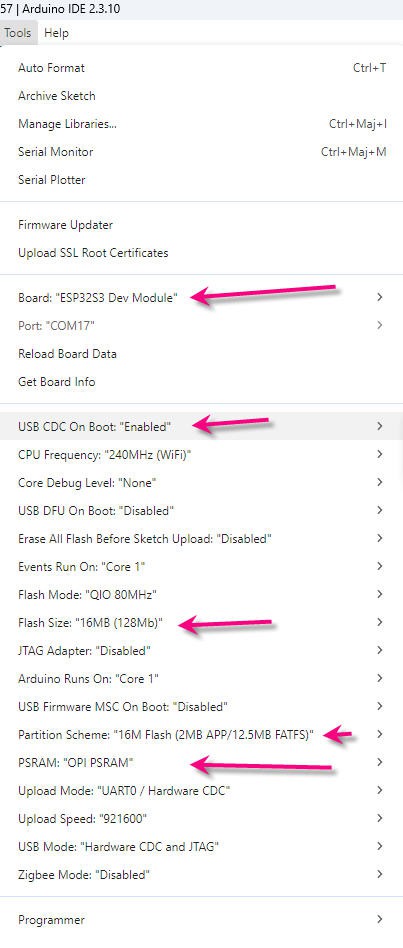
You have to activate this port in the arduino IDE. Here are the full settings for the code to work and compile !
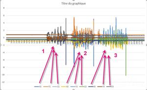
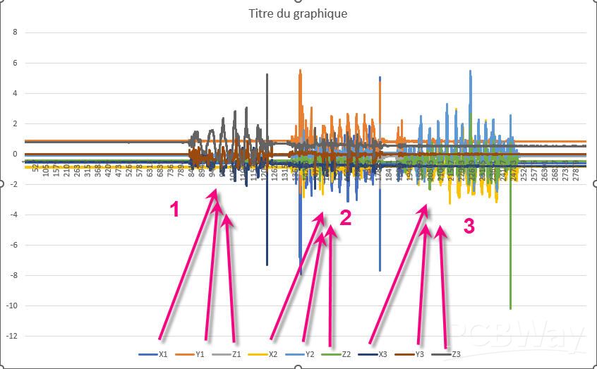
And here is the evidence that everything works fluently !
I did shake the sensors one after the other !
ESP32-S3 3 x ADXL357 acquisition board
Project images are for reference only. Actual production is based on the manufacturing files on the project page.
Please review the designer's notes (e.g., PCB thickness) and select the appropriate options.
PCBWay is not responsible
for issues caused by unsuitable parameter selections.
For more important ordering information, please refer to
Read More









Raspberry Pi 5 7 Inch Touch Screen IPS 1024x600 HD LCD HDMI-compatible Display for RPI 4B 3B+ OPI 5 AIDA64 PC Secondary Screen(Without Speaker)
BUY NOW

- Comments(0)
- Likes(0)
More by Jean-Pierre Gleyzes
-
 RC radial engine spark plug heater
BackgroundMy friend bought this wonderful engine from UMS_technologiesIt's a 7 cylinders star engine...
RC radial engine spark plug heater
BackgroundMy friend bought this wonderful engine from UMS_technologiesIt's a 7 cylinders star engine...
-
 Convert a DC motor into a stepper one
This project is a way to convert a DC motor into a stepper motor.Of course "conversion" will not be ...
Convert a DC motor into a stepper one
This project is a way to convert a DC motor into a stepper motor.Of course "conversion" will not be ...
-
 OpenxSensor variometer and telemetry for RC planes
Ever wanted a very cheap variometer on your RC glider ?battery voltage monitoring ?extra RC channels...
OpenxSensor variometer and telemetry for RC planes
Ever wanted a very cheap variometer on your RC glider ?battery voltage monitoring ?extra RC channels...
-
 A water based tide clock (3d model)
Full details are available on this project page : https://www.pcbway.com/project/shareproject/A_wate...
A water based tide clock (3d model)
Full details are available on this project page : https://www.pcbway.com/project/shareproject/A_wate...
-
 A water based tide clock
SpecificationsTide clocks are generally built from a quartz clock mechanism with an approximate peri...
A water based tide clock
SpecificationsTide clocks are generally built from a quartz clock mechanism with an approximate peri...
-
 ESP32-S3 3 x ADXL357 acquisition board
SpecificationMy son wanted a high accuracy accelerometer board to characterize a vibrating pot.Here ...
ESP32-S3 3 x ADXL357 acquisition board
SpecificationMy son wanted a high accuracy accelerometer board to characterize a vibrating pot.Here ...
-
 ESP32 Linky Teleinfo (TIC) to MQTT – Real-Time Home Assistant Integration
The teleinfo component allows you to retrieve data from a French electrical counter using Teleinform...
ESP32 Linky Teleinfo (TIC) to MQTT – Real-Time Home Assistant Integration
The teleinfo component allows you to retrieve data from a French electrical counter using Teleinform...
-
 Air Quality station (e-paper and Home Assistant)
OverviewThis DIY air quality monitoring system integrates precision sensors with a connected process...
Air Quality station (e-paper and Home Assistant)
OverviewThis DIY air quality monitoring system integrates precision sensors with a connected process...
-
 2S LiPo High-Current Power Box with two Sbus inputs
Project Overview: 2S LiPo High-Current Power Box with two Sbus inputsThis circuit is a high-performa...
2S LiPo High-Current Power Box with two Sbus inputs
Project Overview: 2S LiPo High-Current Power Box with two Sbus inputsThis circuit is a high-performa...
-
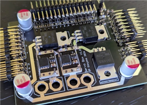 Power box for big RC plane
Project Overview: 2S LiPo High-Current Power BoxThis circuit is a high-performance power distributio...
Power box for big RC plane
Project Overview: 2S LiPo High-Current Power BoxThis circuit is a high-performance power distributio...
-
 A bluetooth Joystick for TX16s radio (or others)
This project is kind of follow on of this one : Buddy Box for Radiomaster TX16sI decided to write an...
A bluetooth Joystick for TX16s radio (or others)
This project is kind of follow on of this one : Buddy Box for Radiomaster TX16sI decided to write an...
-
 Radiomaster TX16s buddy box (master/trainer and more)
I wanted a wireless buddy box for my Radiomaster TX16sThis buddy box would allow to wireless link tw...
Radiomaster TX16s buddy box (master/trainer and more)
I wanted a wireless buddy box for my Radiomaster TX16sThis buddy box would allow to wireless link tw...
-
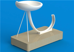 "perpetual" motion ball
Browsing internet and youtube, I found this mind blowing "perpetual motion" device designed by Willi...
"perpetual" motion ball
Browsing internet and youtube, I found this mind blowing "perpetual motion" device designed by Willi...
-
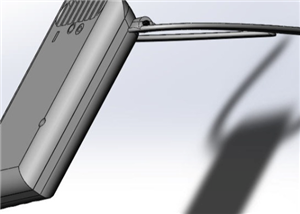 Freon: Freeze On Neck - 3d printed box top
Freon project is fully describbed on this project page
Freon: Freeze On Neck - 3d printed box top
Freon project is fully describbed on this project page
-
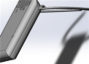 Freon: Freeze On Neck - 3d printed box bottom
Freon project is fully described on this project page
Freon: Freeze On Neck - 3d printed box bottom
Freon project is fully described on this project page
-
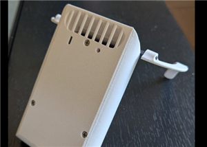 Freon: Freeze On Neck personal cooler
DescriptionAre you tired of sweltering through hot days, feeling uncomfortable and unproductive?Imag...
Freon: Freeze On Neck personal cooler
DescriptionAre you tired of sweltering through hot days, feeling uncomfortable and unproductive?Imag...
-
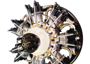 ESP32_StarMotor_glow plugs heater _ V2
BackgroundMy friend bought this wonderful engine from UMS_technologiesIt's a 7 cylinders star engine...
ESP32_StarMotor_glow plugs heater _ V2
BackgroundMy friend bought this wonderful engine from UMS_technologiesIt's a 7 cylinders star engine...
-
 RC plane CoG finder
IntroductionAs an intro here is a video of the system runningand another using the LCD displayA litt...
RC plane CoG finder
IntroductionAs an intro here is a video of the system runningand another using the LCD displayA litt...
-
SmallOLED - Live PC Stats, Animated Clocks & Audio Visualizer
756 0 3 -
"Talking Multimeter": Arduino-Based Speech Add-on for Multimeters with SCPI Protocol
429 0 1 -
Programmable Mist Maker - XIAO / QT PY Extension
2881 2 3 -
RadioHAT - Raspberry Pi radio development platform
2463 0 4 -
-
-
-
ARPS-2 – Arduino-Compatible Robot Project Shield for Arduino UNO
4547 0 6


















