


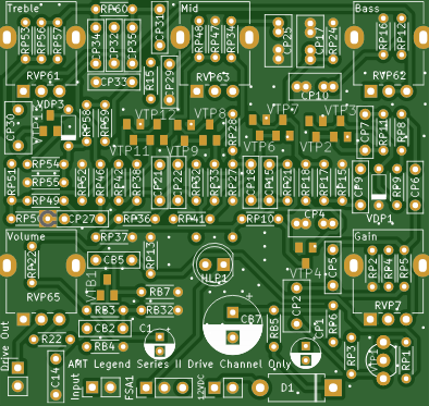
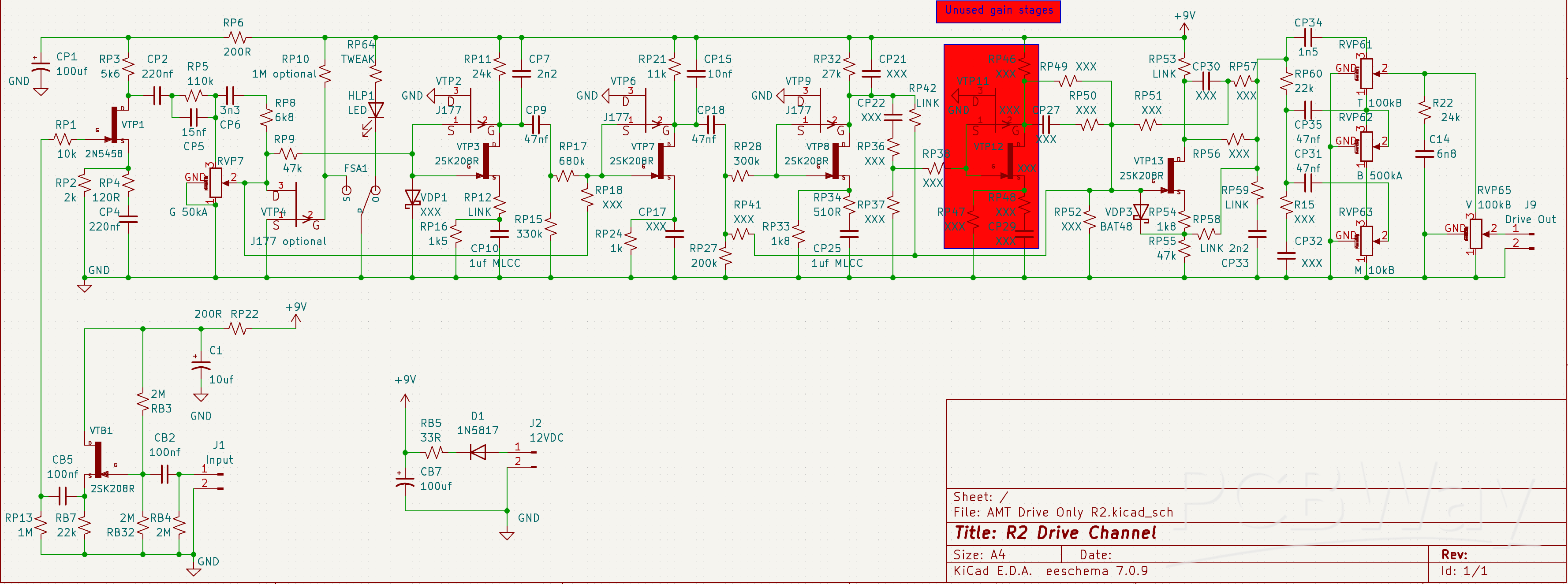
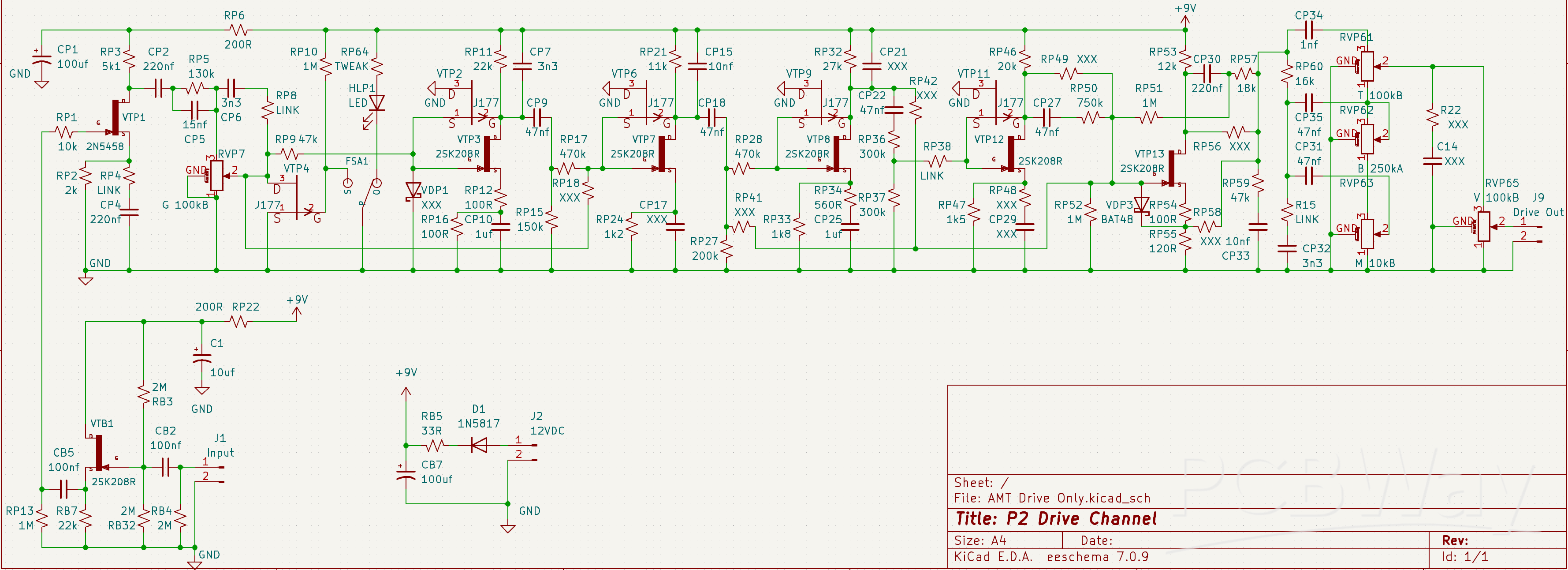
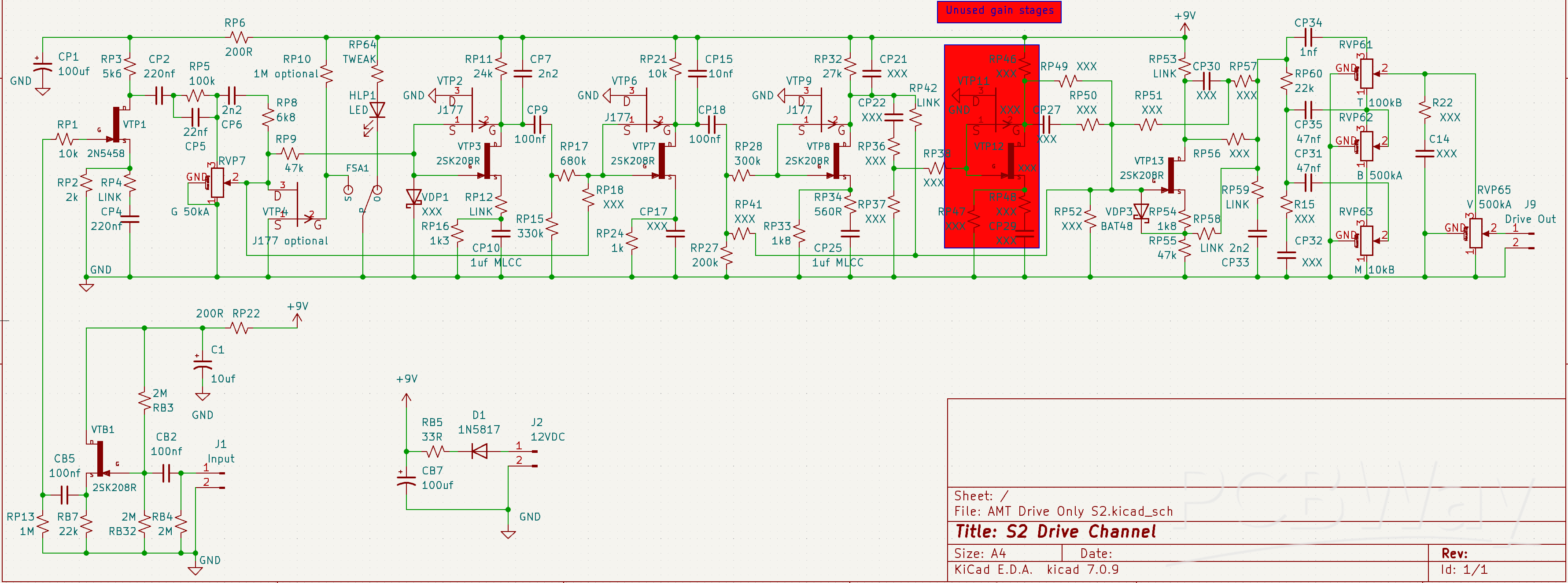
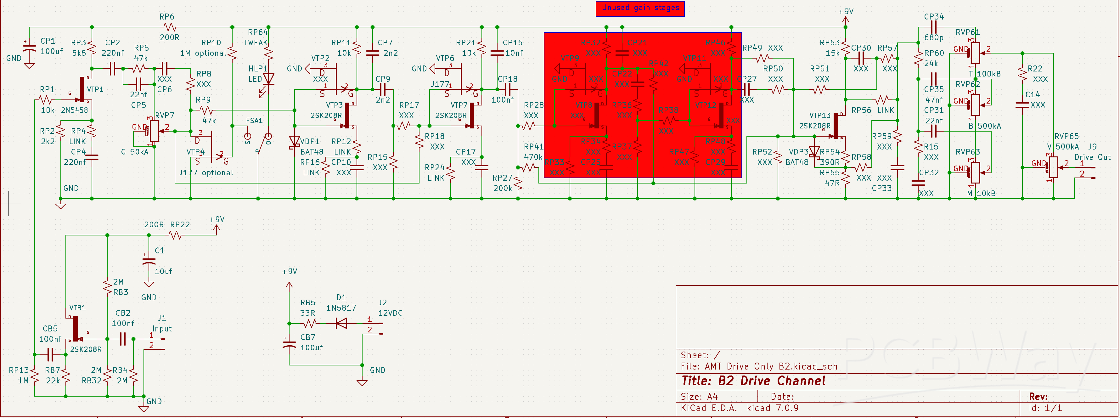
AMT Legend Series II Drive Channel ONLY
This PCB can implement any of the AMT Legend Series II drive channels. Does not include the clean channel or cab sim. This will fit easily in a 125B case.
I also have a PCB that includes the clean channel and cab sim here: https://www.pcbway.com/project/shareproject/M2_Guitar_module_for_combo_embedded_projects_0a1b466c.html
Be warned... These PCBs use SMD transistors. PCBWay can mount those for you but each model has different ones populated. Populating them all is not the right thing to do. To do this yourself, I suggest a bit of solder paste lightly applied to pads with a tooth pick, stick the transistors onto the paste and then put the PCB on a hot plate until the solder flows. This is the hot plate I use:
https://www.amazon.com/dp/B07W1ZZH8T?ref_=ppx_hzsearch_conn_dt_b_fed_asin_title_1
I have some videos showing how I solder SMD components here...
First Video is the application of solder paste with a tooth pick to the PCB.
This is using a very tiny amount of no-clean solder paste.
I’m careful not to leave any paste anywhere but where it is supposed to be.
https://drive.google.com/file/d/1lt_ZqyDOzroHl71-aa7eTO1sPOqIvmZi/view?usp=drive_link
Second Video is the application of solder paste with a tooth pick to the bottom of a TPA3118.
This ensures there will be enough solder and some flux on the IC to get a good solder flow.
https://drive.google.com/file/d/1sV1S1fdVRavs7U-p2nuOOFPRRwq1SbFu/view?usp=drive_link
Third Video is flowing the solder and adding the TPA3118.
Note, for transistors, stick them all to the paste at once while cold, then put the PCB on the hot plate.
The hot plate is already up to temperature, about 325 Fahrenheit.
The PCB is laid onto the plate and wait for the solder to all flow and wick onto the pads.
Then the IC is applied with some pointy tweezers and nudged into place.
Then the PCB is carefully removed from the hot plate and set aside to cool.
https://drive.google.com/file/d/1O_xk2ix7Je_61Z00tFmFoQ9teNyKT7G9/view?usp=drive_link
Fourth Video Buffing any little solder remnants with a tooth pick and brushing.
You can see some very tiny beads being knocked off by the tooth pick.
https://drive.google.com/file/d/1FRlDJYWNrmMDcHIsJxUTkVqsknLjimx4/view?usp=drive_link
Final Video is cleaning with 99% IPA.
Clean it all up with IPA and inspect for anything wrong under the microscope.
https://drive.google.com/file/d/18zwHHAlTBkC1kf13lI_0zVwgchezy74N/view?usp=drive_link
The following interactive BOMs can be used to populate some versions of the drive channel.
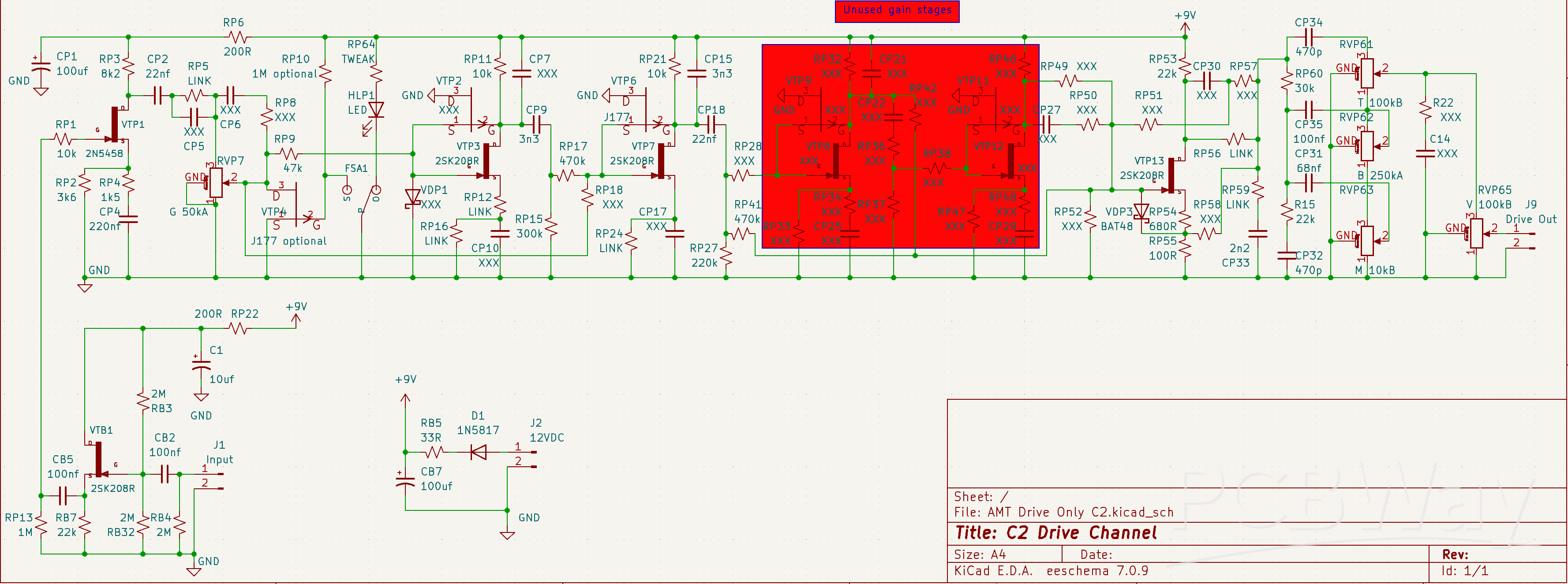
C2: https://paulamps.com/boms/AMTDriveOnly/AMT%20Drive%20Only%20C2.html
E2: https://paulamps.com/boms/AMTDriveOnly/AMT%20Drive%20Only%20E2.html
K2: https://paulamps.com/boms/AMTDriveOnly/AMT%20Drive%20Only%20K2.html
M2: https://paulamps.com/boms/AMTDriveOnly/AMT%20Drive%20Only%20M2.html
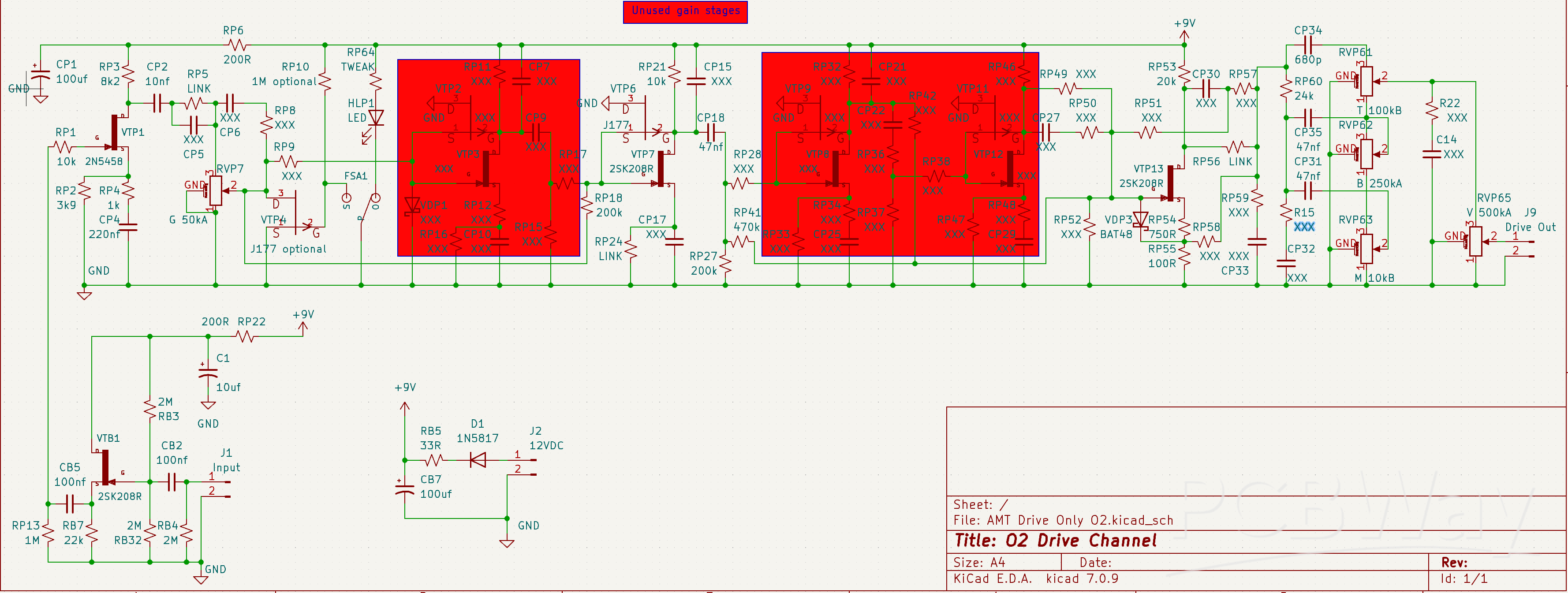
O2: https://paulamps.com/boms/AMTDriveOnly/AMT%20Drive%20Only%20O2.html
R2: https://paulamps.com/boms/AMTDriveOnly/AMT%20Drive%20Only%20R2.html
P2: https://paulamps.com/boms/AMTDriveOnly/AMT%20Drive%20Only%20P2.html
S2: https://paulamps.com/boms/AMTDriveOnly/AMT%20Drive%20Only%20S2.html
B2: https://paulamps.com/boms/AMTDriveOnly/AMT%20Drive%20Only%20B2.html
D2: https://paulamps.com/boms/AMTDriveOnly/AMT%20Drive%20Only%20D2.html
Step one: Use a sharpie on the PCB to mark out all the components labeled XXX in the BOM. These are not installed.
Step two: SMD transistors using solder paste and a hot plate.
Step three: Resistors. Save trimmed leads for jumpers.
Step four: Install jumpers for all components labeled LINK.
Then diodes, caps, 2n5458 and pots.
All POTs are Alpha 9mm:
https://smallbear-electronics.mybigcommerce.com/single-gang-9mm-right-angle-pc-mount/
These pots limit the height of ALL other components to 10mm or less for case clearance!
All resistors are YAGEO 1.9 mm x 3.4 mm 166 mW Metal Film:
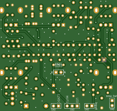
Note that some resistors are underneath the pots, so you must use these small resistors there. But, you can use larger 1/4W resistors elsewhere standing up instead of laying flat. Resistors can also go on the back of the board but be careful not to block locations for input/output jacks in the case. The intent of this build is to install all components on the top side with only one exception: the current limiting resistor, RP64, for the LED so you can choose brightness after having built the pedal. This leaves room for jacks to overlap the location of the board in a 125B case. But, there is very little room. Even small resistors on the back of the board will not allow the jacks to fit.
Capacitors less than 1nf are ceramic:
Signal capacitors from 1nf to 220nf are KEMET Polyester Film:
Signal capacitors 330nf and above are MLCC to limit the height below 10mm.
Electrolytic caps must be under 10mm tall. These are suitable 10uf and 100uf caps:
10uf: https://www.mouser.com/ProductDetail/KEMET/ESS106M035AC2EA?qs=9RUIYXQlAdDELwYaBIsKWw%3D%3D
100uf: https://www.mouser.com/ProductDetail/Rubycon/35ML100MEFC8X7.5?qs=T3oQrply3y%252BVMudpVXVKFw%3D%3D
Semiconductor links:
J177 https://www.mouser.com/c/?q=863-MMBFJ177LT1G
2SK208R https://www.mouser.com/ProductDetail/Toshiba/2SK208-RTE85LF?qs=iCzJi%2FIZBF52K9IBnicZ%2FA%3D%3D
BAT48 https://www.mouser.com/ProductDetail/STMicroelectronics/BAT48?qs=JV7lzlMm3yLztdLrSLKoPQ%3D%3D
BAT41 can also be used and might be a better match to the original real pedals. I've used BAT48 in all my builds and like them. BAT41 have a bit lower forward voltage, so a little more distortion in a drive pedal.


AMT Legend Series II Drive Channel ONLY
*PCBWay community is a sharing platform. We are not responsible for any design issues and parameter issues (board thickness, surface finish, etc.) you choose.


Raspberry Pi 5 7 Inch Touch Screen IPS 1024x600 HD LCD HDMI-compatible Display for RPI 4B 3B+ OPI 5 AIDA64 PC Secondary Screen(Without Speaker)
BUY NOW


- Comments(2)
- Likes(2)
 More by Paul Ruby
-
 AMT Legend Series II Drive Channel ONLY
This PCB can implement any of the AMT Legend Series II drive channels. Does not include the clean ch...
AMT Legend Series II Drive Channel ONLY
This PCB can implement any of the AMT Legend Series II drive channels. Does not include the clean ch...
-
 B2/C2/E2/K2/M2/O2 Guitar preamp module for combo embedded projects.
This has the Fender clean, Marshall Drive (and others options for drive channel) and Cab Sim modules...
B2/C2/E2/K2/M2/O2 Guitar preamp module for combo embedded projects.
This has the Fender clean, Marshall Drive (and others options for drive channel) and Cab Sim modules...
-
 Bobby / Cetus / John (Sheriff / Kraken / Jack) PCB for embedded Guitar distortion module
This is an alternate PCB for the Bobby / Cetus / John (Sheriff / Kraken / Jack) boards at PedalPCB.c...
Bobby / Cetus / John (Sheriff / Kraken / Jack) PCB for embedded Guitar distortion module
This is an alternate PCB for the Bobby / Cetus / John (Sheriff / Kraken / Jack) boards at PedalPCB.c...
-
 Tube Screamer guitar boost board for embedding in a combo guitar pedal format.
This is the classic Tube Screamer circuit implemented on a board as small as possible for embedding ...
Tube Screamer guitar boost board for embedding in a combo guitar pedal format.
This is the classic Tube Screamer circuit implemented on a board as small as possible for embedding ...
-
 Alternate PCB for ADHD guitar overdrive at PedalPCB.com for embedding into modular combo guitar pedal.
Alternate PCB for ADHD guitar overdrive at PedalPCB.com for embedding into modular combo guitar peda...
Alternate PCB for ADHD guitar overdrive at PedalPCB.com for embedding into modular combo guitar pedal.
Alternate PCB for ADHD guitar overdrive at PedalPCB.com for embedding into modular combo guitar peda...
-
 Plexi Drive pre-boost module for embedding into a combo Guitar pedal.
A Marshall Plexi Drive module for embedding in a combo guitar pedal as a pre-boost. This can use eit...
Plexi Drive pre-boost module for embedding into a combo Guitar pedal.
A Marshall Plexi Drive module for embedding in a combo guitar pedal as a pre-boost. This can use eit...
-
 Simplified Prince of Tone pre-boost module for embedding into combo guitar pedals.
This is my version of a Prince of Tone pre-boost module for embedding in a combo guitar pedal. There...
Simplified Prince of Tone pre-boost module for embedding into combo guitar pedals.
This is my version of a Prince of Tone pre-boost module for embedding in a combo guitar pedal. There...
-
 Malachite ovedrive from PedalPCB.com in modular format for embedding in a combo guitar pedal.
This is an alternative PCB for the Malachite Overdrive available at PedalPCB.com for embedding in a ...
Malachite ovedrive from PedalPCB.com in modular format for embedding in a combo guitar pedal.
This is an alternative PCB for the Malachite Overdrive available at PedalPCB.com for embedding in a ...
-
 Small guitar Clean Boost circut for embedding into modular Guitar pedal projects.
This is a very simple guitar lead boost circuit meant for embedding into modular guitar pedals.Inter...
Small guitar Clean Boost circut for embedding into modular Guitar pedal projects.
This is a very simple guitar lead boost circuit meant for embedding into modular guitar pedals.Inter...
-
 Keyed Noise Gate for Modular Guitar Pedal Board Using 4305Q16-U Dynamics Processor
This is an alternative PCB for the Muzzle project at PedalPCB.com in order to make it as small as po...
Keyed Noise Gate for Modular Guitar Pedal Board Using 4305Q16-U Dynamics Processor
This is an alternative PCB for the Muzzle project at PedalPCB.com in order to make it as small as po...
-
 Spin FV-1 Embedded Project Board
This is a smaller version of the Pythagoras from PedalPCB.com for creating Reverb, Delay, Flange or ...
Spin FV-1 Embedded Project Board
This is a smaller version of the Pythagoras from PedalPCB.com for creating Reverb, Delay, Flange or ...
-
 THAT1646 Balanced XLR using dual-ended power supply (+/-15VDC)
Small balanced XLR driver that can be embedded in any project that has dual-ended power available (+...
THAT1646 Balanced XLR using dual-ended power supply (+/-15VDC)
Small balanced XLR driver that can be embedded in any project that has dual-ended power available (+...
-
 THAT1646 Balanced XLR using singled-ended power supply (20 to 30VDC)
I used this to add an XLR balanced output to my pedal-board power amp, which runs on 24Vdc without a...
THAT1646 Balanced XLR using singled-ended power supply (20 to 30VDC)
I used this to add an XLR balanced output to my pedal-board power amp, which runs on 24Vdc without a...
-
 TMB with Discrete Soft-Touch Footswitch for 125B Pedal Board Power Amplifier
The is a preamp board that can be sandwiched with a preexisting TPA3118 power amp module to make a p...
TMB with Discrete Soft-Touch Footswitch for 125B Pedal Board Power Amplifier
The is a preamp board that can be sandwiched with a preexisting TPA3118 power amp module to make a p...
-
 TMB with Digispark Soft-Touch Footswitch for 125B Pedal Board Power Amplifier
The is a preamp board that can be sandwiched with a preexisting TPA3118 power amp module to make a p...
TMB with Digispark Soft-Touch Footswitch for 125B Pedal Board Power Amplifier
The is a preamp board that can be sandwiched with a preexisting TPA3118 power amp module to make a p...
-
 TMB with ATtiny Soft-Touch Footswitch for 125B Pedal Board Power Amplifier
The is a preamp board that can be sandwiched with a preexisting TPA3118 power amp module to make a p...
TMB with ATtiny Soft-Touch Footswitch for 125B Pedal Board Power Amplifier
The is a preamp board that can be sandwiched with a preexisting TPA3118 power amp module to make a p...
-
 TPA3118 Power-Amplifier Module
This TPA3118 Power Amplifier Module is meant to be combined with one of the preamp board projects al...
TPA3118 Power-Amplifier Module
This TPA3118 Power Amplifier Module is meant to be combined with one of the preamp board projects al...
-
 Volume-Only with Digispark Soft-Touch Footswitch for 125B Pedal Board Power Amplifier
The is a preamp board that can be sandwiched with a preexisting TPA3118 power amp module to make a p...
Volume-Only with Digispark Soft-Touch Footswitch for 125B Pedal Board Power Amplifier
The is a preamp board that can be sandwiched with a preexisting TPA3118 power amp module to make a p...
-
Programmable Mist Maker - XIAO / QT PY Extension
365 0 0 -
RadioHAT - Raspberry Pi radio development platform
303 0 1 -
-
-
-
-
ARPS-2 – Arduino-Compatible Robot Project Shield for Arduino UNO
2857 0 6 -
A Compact Charging Breakout Board For Waveshare ESP32-C3
3360 3 8 -
AI-driven LoRa & LLM-enabled Kiosk & Food Delivery System
3674 2 2


