


|
KiCad 9.0 |
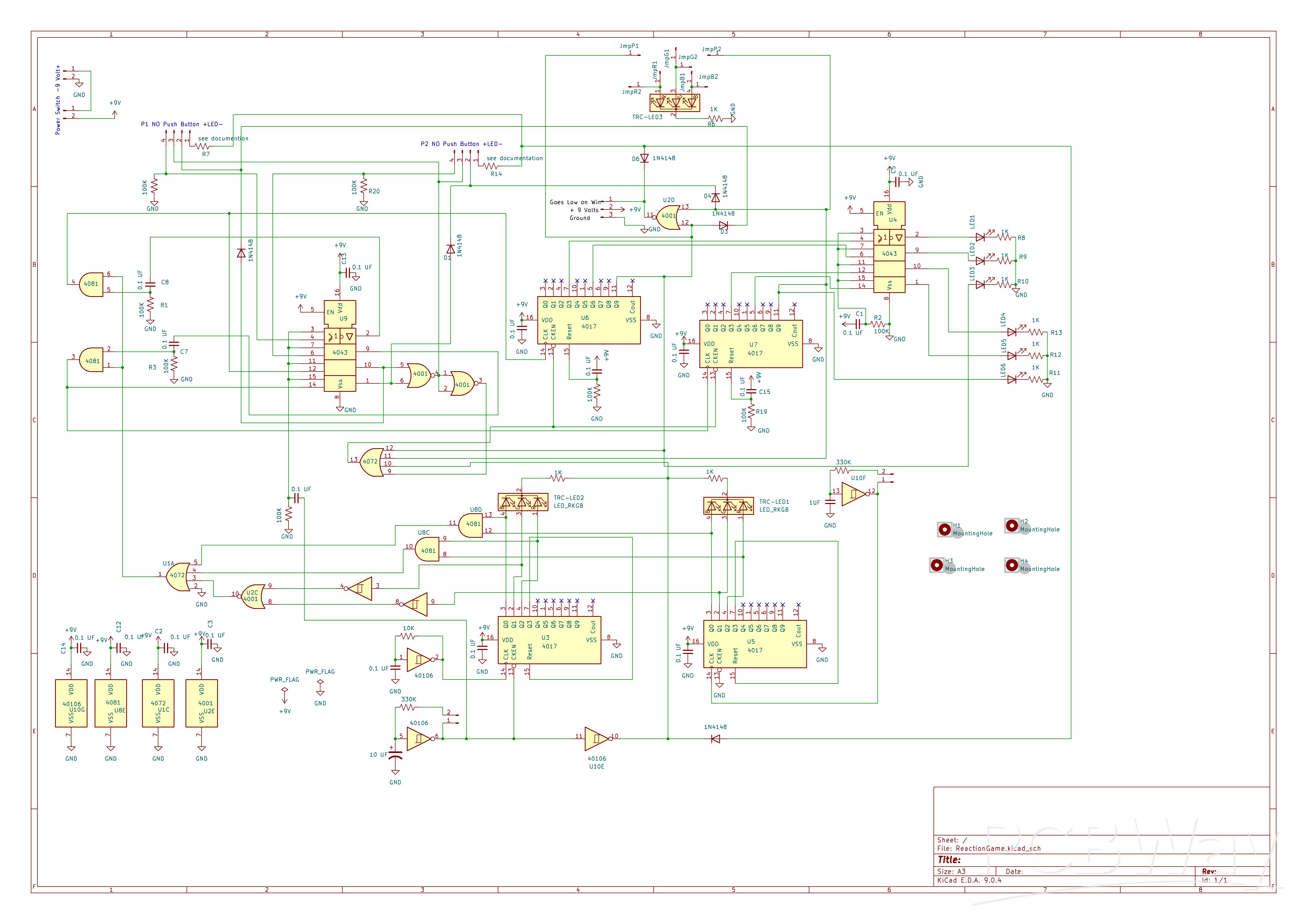
Reaction Game
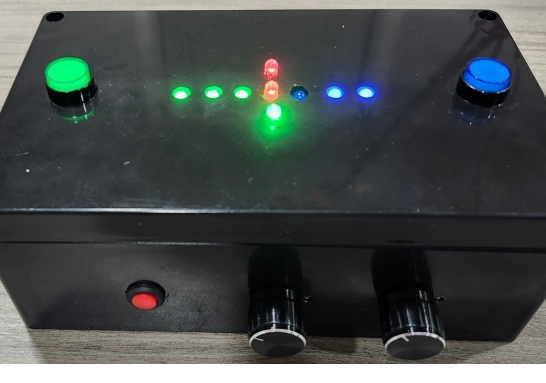
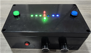
This game utilizes two tricolor LEDs. One LED randomly lights up in blue, green, or red. The second LED cycles through these colors in a random order—blue, green, and red—at least once before both LEDs turn off, approximately four seconds later. This process then repeats. The setup is intended for two players, whose goal is to press their button when the illuminated colors match\
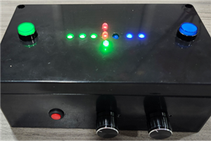
Each LED activation constitutes a round. Two potentiometers control the speed of each round and the speed at which the second LED cycles through colors, respectively. Each player has three LEDs to display their score: the first illuminates at 3 points, the second at 6 points, and the third at 9 points. created. A third tricolor LED will light up in red, green, or blue to indicate the winner.
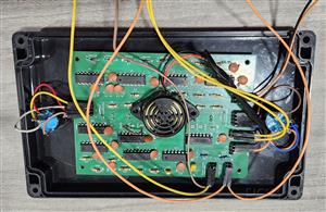
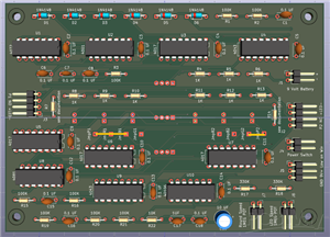
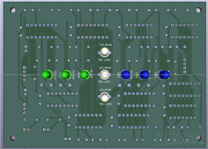
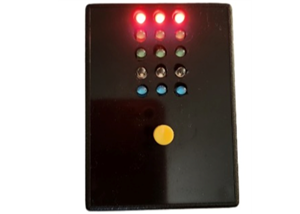
I recently redesigned the board so that all the LEDs are on one side and all other components are on the opposite side. The board mounts on top of a project case with holes drilled for the LEDs. The board has four corner holes for mounting, or you can use double-sided foam tape.
For scoring, I suggest using different-colored LEDs and push buttons for each player—red, green, and blue LEDs work well. I have used combinations like (red and green), (red and blue), and (blue and green). The third LED, which indicates the winner, is controlled by two jumper wires on each side of the board. From left to right, the jumper connections are labeled JmpP1, JmpR1, JmpB1, JmpG1, JmpR2, JmpB2, JmpG2, and JmpP2. If Player 1 is red and Player 2 is green, solder a jumper wire from JmpP1 to JmpG2 and another from JmpP2 to JmpG2. In this setup, the tri-color LED will light up either red or green depending on who wins.
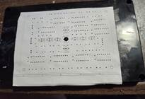
You can find the KiCad project files as a zip under “other files for assembly.” Inside, there’s a template.pdf that you can print and use to guide your LED drilling. To secure the template to the top of the case, I suggest using an adhesive like Elmer’s All Purpose Glue Stick. The case I selected has a small center mark on its top, which helped me align the template—just punch a hole in the template at that spot. Once you finish drilling, simply soak the template in warm water with dish detergent or soap to remove it.
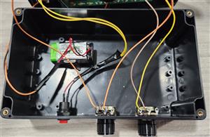
For the illuminated push buttons, utilize a 16 mm drill bit; for the power switch, use a 12 mm drill bit; and for the potentiometers, employ a 9 mm drill bit. The potentiometers include a small tab that requires a 3.2 mm drill bit to create an appropriate hole. To accurately mark the location for this hole, position the potentiometer with the shaft facing inward and the solder lugs pointing downward inside the enclosure. Use the tab to make a slight scratch on the exterior of the case, which will serve as a guide for drilling the tab hole.

Resistors R7 and R14 serve as current-limiting components for LED push buttons. Since the specific push buttons selected do not require these resistors, jumper wires or zero-ohm resistors may be substituted as appropriate. The inclusion of space for these resistors is intended to provide enhanced design flexibility.
The button belonging to the winning player remains illuminated, and a brief sequence of notes plays until the game is reset. To reset the game, you can turn the power off and back on, or add a normally closed, momentary push-button in series with the power switch to serve as a reset button.
The notes are produced by an optional circuit. Optional circuit Note Sequencer https://www.pcbway.com/project/shareproject/Note_Sequencer_Updated_7_16_2025_5b2919b3.html
Connect potentiometers, push buttons, power switch, battery connector, and the optional tone sequencer circuit to the PC Board using header pins and female-ended wires. The Note Sequencer attaches to the output pins labeled “GND 9V+ Low on Win” (matching the sequencer’s “-,9V+,Start Low”). Alternatively, you can add an active piezo buzzer to beep when the game ends by connecting it to 9V+ and Start Low; GND is not used in this case.
YouTube video https://youtu.be/gYBMlOfJTuA?si=EvH6nGLHjCtxcqD1
Suggestions for a name for this project: Rainbow Match, Rainbow Reaction, or LED Match.
Reaction Game
*PCBWay community is a sharing platform. We are not responsible for any design issues and parameter issues (board thickness, surface finish, etc.) you choose.


Raspberry Pi 5 7 Inch Touch Screen IPS 1024x600 HD LCD HDMI-compatible Display for RPI 4B 3B+ OPI 5 AIDA64 PC Secondary Screen(Without Speaker)
BUY NOW


- Comments(0)
- Likes(2)
More by William Harter
-
 Slot Machine
This slot machine project uses 15 colored LEDs for three reels, operated by a single push-button tha...
Slot Machine
This slot machine project uses 15 colored LEDs for three reels, operated by a single push-button tha...
-
 Reaction Game
This game utilizes two tricolor LEDs. One LED randomly lights up in blue, green, or red. The second ...
Reaction Game
This game utilizes two tricolor LEDs. One LED randomly lights up in blue, green, or red. The second ...
-
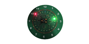 LED Ring Clock
Display OverviewThe inner LED ring shows the hour: yellow on the hour and green on the...
LED Ring Clock
LED Ring ClockDisplay OverviewThe inner LED ring shows the hour: yellow on the hour and green on the...
-
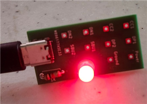 Test USB C board
I needed to add a USB C connector as the power input for one of my current projects. This board was ...
Test USB C board
I needed to add a USB C connector as the power input for one of my current projects. This board was ...
-
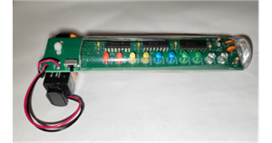 Pumpkin / Jack o'lantern light
This light for a pumpkin or Jack o'lantern operates on a single 9-volt battery and cycles through fi...
Pumpkin / Jack o'lantern light
This light for a pumpkin or Jack o'lantern operates on a single 9-volt battery and cycles through fi...
-
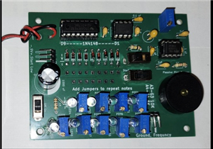 Note Sequencer
This project utilizes two low power 555 timers (TS555CN) and a 4017 counter to produce...
Note Sequencer
Note SequencerThis project utilizes two low power 555 timers (TS555CN) and a 4017 counter to produce...
-
Programmable Mist Maker - XIAO / QT PY Extension
171 0 0 -
RadioHAT - Raspberry Pi radio development platform
180 0 1 -
-
-
-
-
ARPS-2 – Arduino-Compatible Robot Project Shield for Arduino UNO
2765 0 5 -
A Compact Charging Breakout Board For Waveshare ESP32-C3
3273 3 8 -
AI-driven LoRa & LLM-enabled Kiosk & Food Delivery System
3527 2 2


