PCBWay Community
Search title or content
Search
PCBWay
PCB Instant Quote
CNC | 3D Printing
Login
Sign Up
More Notifications
No notifications.
My Profile
My projects
My Likes
My Deals
My Goods for Bazaar
Settings
Sign Out
Projects
Categories
DIY Electronics
Arduino
Hardware
Audio
Computers & USB
Breakout Board Projects
Home Automation
LED Displays & Matrices
IoT
Robotics
View all categories
By Source Files
Onju Voice - AI assistant replacement to Google Nest Mini by @justLV
LogicAnalyzer V6.0
DIY 1kW Open Source MPPT Solar Charge Controller
Tad Boy Color
SummerCart64 - a fully open source N64 flashcart
kv4p HT v1.7b
QuinLED-Dig-Uno
Bike Fingerprint - PCB
Arduino RC engine sound & light controller with inertia simulation for ESP32
Solar Powered WiFi Weather Station V2.0
SIDKick pico 0.2 (SID 6581/8580-replacement for C64/C128)
Frog Boy Color
View all source files projects
Featured Projects
Onju Voice - AI assistant replacement to Google Nest Mini by @justLV
LogicAnalyzer V6.0
DIY 1kW Open Source MPPT Solar Charge Controller
Featured
Source Files
Video
View all projects
Questions
Sponsorships
Feedback
Blog
Store
PCB Design
Contest
- 2026 KiCad PCB Design Contest
- 8th Project Design Contest
- 7th Project Design Contest
- KiCad Design Contest
- 6th Project Design Contest
- 5th PCB Design Contest
- 4th PCB Design Contest
- Raspberry Pi Pico Contest
- PCB Design Tutorial
- 3rd PCB Design Contest
- I CAN SOLDER Kit Contest
- 2nd PCB Design Contest
- 1st PCB Design Contest
Add questions
Create a project
Please verify your email address so that you can enjoy our more comprehensive services.
Wearables
Weather
All categories
DIY Electronics
Arduino
Hardware
Audio
Computers & USB
Breakout Board Projects
Home Automation
LED Displays & Matrices
IoT
Robotics
3D Printing
Blinkenlights
Calculator
Camera
Clocks
CNC
Educational
Automotive
Electronic Games
ESP32
Fabrication Tools
Flight
Guitar
Keyboards
Misc
Music
Nixie Tube
Oscilloscope
Particle
Power Supply
Programmable Logic Projects
Raspberry Pi
Radio
Retro Stuffs
Space & Satellite
Sensors
Software
Synthesizer
Ultrasonic
Virtual Reality
Wearables
Weather
Project by top creative fields
All categories
3D Printing
Arduino
Audio
Automotive
Blinkenlights
Breakout Board Projects
Calculator
Camera
Clocks
CNC
Computers & USB
DIY Electronics
Educational
Electronic Games
ESP32
Fabrication Tools
Flight
Guitar
Hardware
Home Automation
IoT
Keyboards
LED Displays & Matrices
Misc
Music
Nixie Tube
Oscilloscope
Particle
Power Supply
Programmable Logic Projects
Radio
Raspberry Pi
Retro Stuffs
Robotics
Sensors
Software
Space & Satellite
Synthesizer
Ultrasonic
Virtual Reality
Wearables
Weather
View all categories
Misc
Misc Electronic.
All tags
Commodore
Retrocomputing
Amiga
Adapter
Cartridge
ESP32
Create a project
Sort by : Trending
Trending
Score
Likes
Views
Discuss
Newest
Featured
Source Files
3D Design
Video
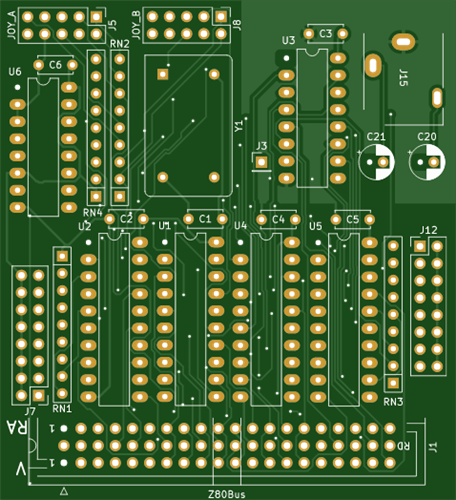
Z80Bus SG-1000 Module.Joystick and Sound.For joystick I use the double serial slot covers.For better sound, piggyback 2 SN76489, only bend pin 7 out and connect to jumper J3
Z80Bus SG-1000
169
0
0
M Voerman
M Voerman
NETHERLANDS, THE
1
6
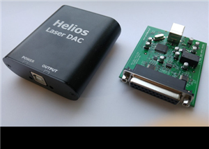
Helios Laser DAC is a USB to ILDA interface/adapter, used for connecting laser show projectors to your computer. It is inexpensive, yet fast and with high resolution. It is compatible with every laser...
Helios DAC V1.21
67
0
0
Engineer
Engineer
UNITED STATES OF AMERICA
0
0
OpenAmiga600RamExpansion is an Open Hardware 1 MB Chip RAM Expansion for the Commodore Amiga 600 Computer.For more information, please visit https://github.com/SukkoPera/OpenAmiga600RamExpansion.
OpenAmiga600RamExpansion V1
9737
7
24
SukkoPera
SukkoPera
ITALY
356
10
This cartridge allows replacing the KERNAL (i.e.: operating system) of a Commodore C64 computer with one that is stored on an external cartridge. Actually it can store up to 8 KERNAL images, which can...
OpenC64KernalCart V1
9146
10
26
SukkoPera
SukkoPera
ITALY
356
10
OpenAmiga600FastRamExpansion is an Open Hardware 4 MB Fast RAM Expansion for the Commodore Amiga 600 Computer.Most low-end Amiga models only came with Chip RAM. "Big Box" models allowed for a dif...
OpenAmiga600FastRamExpansion V1
5620
4
18
SukkoPera
SukkoPera
ITALY
356
10
Practice makes perfect and soldering needs a lot of it...This 100x100mm board contains all the features you will need in order to practice your soldering, improve your skills and boost your confidence...
MuteFPV Ultimate Soldering Practice Board
24517
4
17
Dimitris muteFPV
Dimitris muteFPV
GREECE
18
0
For details please see the video belowUnboxing Paket PCB dari PCBWayhttps://fareedish.blogspot.com/2020/02/membuat-cas-aki-otomatis-dengan-mudah.html
Automatic Battery Charger NE555
36108
2
16
Fareed Fareed Read
Fareed Fareed Read
INDONESIA
312
62
This sleek cover solves one issue: refrigerator taste. If you leave a jug of water uncovered in your refrigerator overnight, it will have a distinctive taste that is unpleasant. This cover solves the ...
IKEA TILLBRINGARE Jug Cover
112
1
1
Philippe Lamarche
Philippe Lamarche
CANADA
0
0
OpenFlops is an Open Hardware Floppy Disk Drive emulator/simulator inspired from the ubiquitous Gotek hardware. It is designed to run the FlashFloppy firmware.For more information please vis...
OpenFlops V1
13159
0
51
SukkoPera
SukkoPera
ITALY
356
10
Components list in MouserThis artistic Christmas PCB was developed for the Julialabs PCB Challange 2022.the hat lights up red, blinking alternately, and the gift lights up rgb-O gorro acende vermelho,...
Christmas Gifter Yoshi
2643
0
5
Bianca Rerre
Bianca Rerre
BRAZIL
3
0
this is a project that i did for the christmas theme competition of a friend who streams on twitch and records for youtube.right when she announced the tournament, I already had the whole idea in my h...
PCB Snowman Xmas
3093
7
38
RodrigoDornelles
RodrigoDornelles
5
0
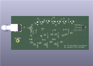
Interested in the feasibility of harvesting ambient RF as part of a school project so I used a network analyzer to determine the strongest frequencies on campus and designed an impedance matching circ...
Three_frequency_RF-Harvester
44
0
0
Alo
Alo
UNITED STATES OF AMERICA
0
0
This project is an artistic Christmas PCB developed for the Julialabs PCB Chanllange 2022.Its a simple PCB, the circuit blink a red led on reindeer´s nose when you touch the back of the paw.Here the f...
Touch Christmas Reindeer
2015
0
6
Fernando Cortes
Fernando Cortes
BRAZIL
3
2
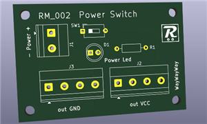
A generic PCB that has power input, a switch to power on up to 4 external circuits and a led showing if the current is flowing through the switch.The components to be installed on the PCB, that is the...
Power Switch module
48
2
0
Renato M.
Renato M.
ITALY
0
0
GCJC Keychain For PCBWay sponsorship promotion
GCJC Keychain
7053
0
6
Shank
Shank
UNITED STATES OF AMERICA
1
0
I bought a second hand FIAT Seicento, then I discovered there was installed a non working car alarm system (Gemini 7300).Alarm was a too old model to get support or repair service. No available replac...
Gemini 7300
2820
2
4
Michele Bertoni
Michele Bertoni
ITALY
2
11
1
2
3
4
5
6
7
8
9
10
11
...