


|
KiCad 9.0 |
Slot Machine
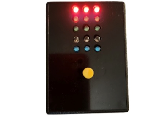
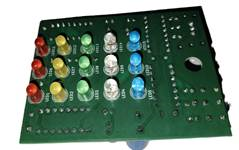
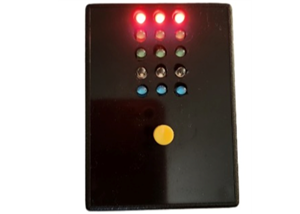
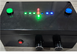
This slot machine project uses 15 colored LEDs for three reels, operated by a single push-button that powers the device, starts the reels, and resets the game. It shuts off automatically after eight minutes of inactivity. You can choose LED colors like red, yellow, green, pink, and blue.
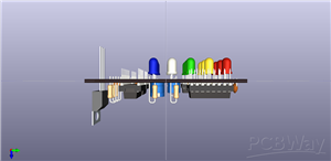
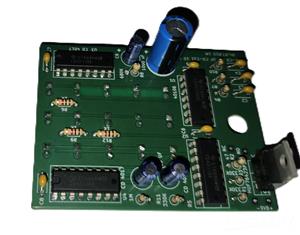
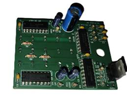
Three CD4017 counters control the reels; each has its own clock circuit powered by a CD40106B CMOS Hex Schmitt-Trigger and a resistor-capacitor combo to set spin duration.
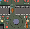
A 6 mm mounting hole on the PC board fits a NO/NC SPST momentary push-button switch, which is wired to COM, NO, and NC terminals. The switch used is listed here. Battery connections are on the board edge for a 9-volt clip.
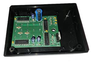
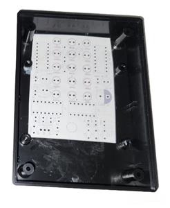
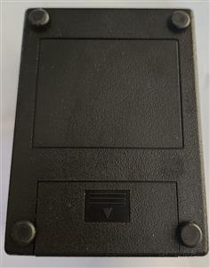
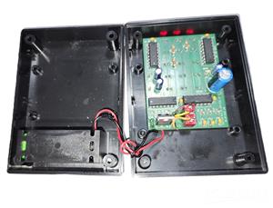
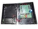
LEDs are mounted on one side of the PCB, with components on the opposite side. The file SlotMachine.zip includes the KiCad files and a PDF template for drilling holes in the enclosure for LEDs and a switch. The recommended enclosure (part PBS-11532-B) measures 4.37” x 3.25” x 1.5” and fits a 9-volt battery, available from DigiKey, Mouser, Techni-Tool, and Vetco Electronics.
This PC board was assembled by PCBWay; final assembly required adding the push button, battery clip, and case installation. I connected the switch using jumper wires intended for breadboarding.
YouTube Link https://youtube.com/shorts/SafDvGwXbNk?si=XxPYlz5tUSNEevR7

Slot Machine
Project images are for reference only. Actual production is based on the manufacturing files on the project page.
Please review the designer's notes (e.g., PCB thickness) and select the appropriate options.
PCBWay is not responsible
for issues caused by unsuitable parameter selections.
For more important ordering information, please refer to
Read More


Raspberry Pi 5 7 Inch Touch Screen IPS 1024x600 HD LCD HDMI-compatible Display for RPI 4B 3B+ OPI 5 AIDA64 PC Secondary Screen(Without Speaker)
BUY NOW


- Comments(0)
- Likes(2)
More by William Harter
-
 Slot Machine
This slot machine project uses 15 colored LEDs for three reels, operated by a single push-button tha...
Slot Machine
This slot machine project uses 15 colored LEDs for three reels, operated by a single push-button tha...
-
 Reaction Game
This game utilizes two tricolor LEDs. One LED randomly lights up in blue, green, or red. The second ...
Reaction Game
This game utilizes two tricolor LEDs. One LED randomly lights up in blue, green, or red. The second ...
-
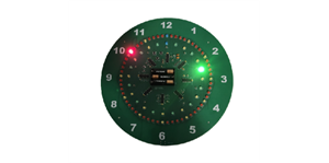 LED Ring Clock
Display OverviewThe inner LED ring shows the hour: yellow on the hour and green on the...
LED Ring Clock
LED Ring ClockDisplay OverviewThe inner LED ring shows the hour: yellow on the hour and green on the...
-
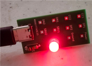 Test USB C board
I needed to add a USB C connector as the power input for one of my current projects. This board was ...
Test USB C board
I needed to add a USB C connector as the power input for one of my current projects. This board was ...
-
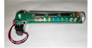 Pumpkin / Jack o'lantern light
This light for a pumpkin or Jack o'lantern operates on a single 9-volt battery and cycles through fi...
Pumpkin / Jack o'lantern light
This light for a pumpkin or Jack o'lantern operates on a single 9-volt battery and cycles through fi...
-
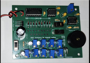 Note Sequencer
This project utilizes two low power 555 timers (TS555CN) and a 4017 counter to produce...
Note Sequencer
Note SequencerThis project utilizes two low power 555 timers (TS555CN) and a 4017 counter to produce...
-
Programmable Mist Maker - XIAO / QT PY Extension
1147 2 1 -
RadioHAT - Raspberry Pi radio development platform
957 0 2 -
-
-
-
-
ARPS-2 – Arduino-Compatible Robot Project Shield for Arduino UNO
3381 0 6 -
A Compact Charging Breakout Board For Waveshare ESP32-C3
3997 3 8 -
AI-driven LoRa & LLM-enabled Kiosk & Food Delivery System
4389 2 2


