


|
fusion360 |
Tiny Power meter V2 – Community Innovation Share
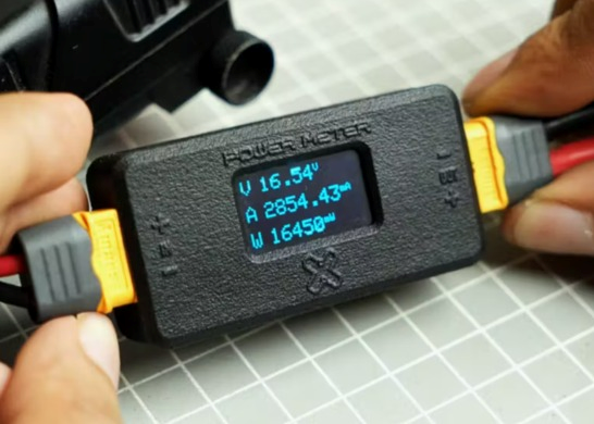
Tiny Power Meter V2 is a compact and practical power measurement device designed to work with XT60 connectors. It allows users to easily measure voltage, current, and power consumption by simply connecting a power source to the input and a load to the output. All values are displayed in real time on a small OLED screen, making it ideal for electronics testing, battery analysis, and FPV drone applications. The project focuses on simplicity, accuracy, and portability while maintaining a clean and professional hardware design.
How It Works
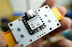
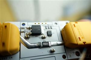
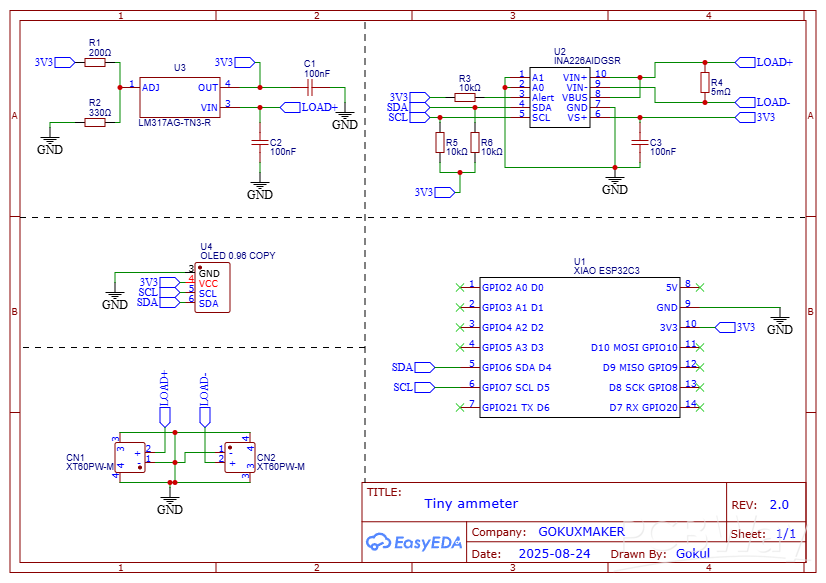
The power meter is built around the Seeed Studio XIAO ESP32-C3, paired with the INA226 high-precision current and power monitoring IC. The INA226 measures the voltage drop across a low-value shunt resistor to calculate current and simultaneously measures the bus voltage. Using these parameters, it computes real-time power consumption. Communication between the INA226, OLED display, and XIAO ESP32-C3 is handled through the I²C bus, keeping the circuit efficient and minimal. The entire system is powered directly from the input voltage, with XT60 connectors used for both input and output.
Key Features
- Current measurement up to ±10 A
- Bus voltage sensing from 5 V to 36 V
- Compact and portable inline power meter
- XT60 connectors for reliable high-current connections
- Real-time display of voltage, current, and wattage
INA226 Current Sensor Explained
The INA226 is a high-accuracy current, voltage, and power monitoring IC that communicates over I²C. It measures the differential voltage across a shunt resistor to calculate current and also monitors the bus voltage to compute power in real time.
The current is calculated using the formula:
Current (I) = Shunt Voltage (Vshunt) / Shunt Resistance (Rshunt)
With a 0.005 Ω shunt resistor and the INA226’s ±81.92 mV full-scale shunt voltage range:
Maximum Current (Imax) = 81.92 mV / 0.005 Ω
Maximum Current (Imax) ≈ 16.38 A
This means the maximum measurable current using this shunt resistor is approximately 16.38 A.
PCB Design
The PCB design is kept compact due to the minimal external components required by the INA226. The schematic and PCB were designed using EasyEDA, and all necessary build files are attached for reference. XT60 connectors are used for both input and output, allowing the power meter to be connected inline without modifying existing setups.
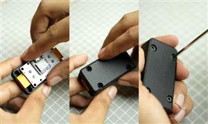
Enclosure Design
The enclosure was designed in Autodesk Fusion 360. The PCB STEP file was imported for accurate fitting and alignment. The enclosure uses a two-part design with a minimum wall thickness of 0.8 mm and is secured using four M3 × 10 mm screws.
Firmware & Calibration
The firmware is written using the Arduino framework and utilizes:
- Adafruit_INA226 library
- Adafruit_SSD1306 library
Calibration is performed using:
ina226.setCalibration(0.005, 10.0);
First parameter: Shunt resistor value (5 mΩ)
Second parameter: Maximum expected current (Amps)
This value can be adjusted based on the application requirements.
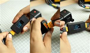
Assembly & Testing
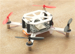
Assembly begins by soldering components according to the schematic. It is recommended to program the XIAO ESP32-C3 before soldering it to the PCB. The OLED display should be mounted carefully to align with the enclosure window. For testing, connect the power source to the XT60 input and the load to the XT60 output. The OLED will immediately display voltage, current, and power readings. XT60 connectors also make it easy to create custom adapters, such as DC jack to XT60 cables, which is especially useful for FPV drone and battery testing applications.
Credit & Acknowledgement
This project is shared for educational and community reference purposes only.
Complete Design & Engineering Credit: Gokul
Community Shared By: Bholu
All technical design, planning, and implementation belong to the original creator. This article is shared to respectfully acknowledge and highlight the work within the PCBWay community, encouraging learning and collaboration.
#include <Wire.h>
#include <Adafruit_SSD1306.h>
#include <Adafruit_INA226.h>
// OLED setup
#define SCREEN_WIDTH 128
#define SCREEN_HEIGHT 64
#define OLED_RESET     -1
#define SCREEN_ADDRESS 0x3C
Adafruit_SSD1306 display(SCREEN_WIDTH, SCREEN_HEIGHT, &Wire, OLED_RESET);
// INA226 setup
Adafruit_INA226 ina226 = Adafruit_INA226();
float busvoltage = 0;
float current_mA = 0;
float power_mW = 0;
void setup() {
Serial.begin(115200);
// Initialize INA226
if (!ina226.begin()) {
Serial.println("Failed to find INA226 chip");
while (1) { delay(10); }
}
// Calibration: 0.005 ohm shunt resistor, max expected current ~10A
// (adjust the 10.0 value for your max current to improve accuracy)
ina226.setCalibration(0.005, 10.0);
// Initialize OLED display
if (!display.begin(SSD1306_SWITCHCAPVCC, SCREEN_ADDRESS)) {
Serial.println("SSD1306 allocation failed");
for (;;);
}
display.clearDisplay();
display.setTextColor(WHITE);
display.setTextSize(1);
display.display();
}
void loop() {
// Read data from INA226
busvoltage = ina226.readBusVoltage();   // Volts
current_mA = ina226.readCurrent() * 1000; // A → mA
power_mW   = ina226.readPower() * 1000;   // W → mW
// Show data on OLED
display.clearDisplay();
display.setCursor(0, 0);
display.setTextSize(2);
display.print("V");
display.setCursor(20, 0);
display.setTextSize(2);
display.print(busvoltage, 2);
display.setTextSize(1);
display.print("V");
display.setCursor(0, 25);
display.setTextSize(2);
display.print("A");
display.setCursor(20, 25);
display.setTextSize(2);
display.print(current_mA, 1);
display.setTextSize(1);
display.print("mA");
display.setCursor(0, 50);
display.setTextSize(2);
display.print("W");
display.setCursor(20, 50);
display.setTextSize(2);
display.print(power_mW, 1);
display.setTextSize(1);
display.print("mW");
display.display();
delay(1000); // update every second
}
Tiny Power meter V2 – Community Innovation Share
*PCBWay community is a sharing platform. We are not responsible for any design issues and parameter issues (board thickness, surface finish, etc.) you choose.


Raspberry Pi 5 7 Inch Touch Screen IPS 1024x600 HD LCD HDMI-compatible Display for RPI 4B 3B+ OPI 5 AIDA64 PC Secondary Screen(Without Speaker)
BUY NOW


- Comments(0)
- Likes(0)
More by Nirmal Maa
-
 VC-02 Module Based Home Automation
In this guide, I’ll take you through the process of building a project using a custom-designed PCB, ...
VC-02 Module Based Home Automation
In this guide, I’ll take you through the process of building a project using a custom-designed PCB, ...
-
 Tiny Power meter V2 – Community Innovation Share
Tiny Power Meter V2 is a compact and practical power measurement device designed to work with XT60 c...
Tiny Power meter V2 – Community Innovation Share
Tiny Power Meter V2 is a compact and practical power measurement device designed to work with XT60 c...
-
 ESP32-Based Drone PCB – Community Innovation Share
Shared by: Bholu, A B-Tech Student in University of California, Los Angeles (UCLA)Original Design &a...
ESP32-Based Drone PCB – Community Innovation Share
Shared by: Bholu, A B-Tech Student in University of California, Los Angeles (UCLA)Original Design &a...
-
 RGB tube light PCB - Panalize under 100*100mm
I'm excited to unveil my latest PCB design—a game-changer for standard tube lights! This custom-desi...
RGB tube light PCB - Panalize under 100*100mm
I'm excited to unveil my latest PCB design—a game-changer for standard tube lights! This custom-desi...
-
 DIY low cost Smart watch
Hello, PCBWay Community! I am thrilled to share my Homemade Smartwatch project with all of you. This...
DIY low cost Smart watch
Hello, PCBWay Community! I am thrilled to share my Homemade Smartwatch project with all of you. This...
-
 4x2 Channel Remote Controller – Receiver Part
The receiver circuit for this 4x2 channel remote controller enables reliable wireless communication ...
4x2 Channel Remote Controller – Receiver Part
The receiver circuit for this 4x2 channel remote controller enables reliable wireless communication ...
-
 DIY Low Cost Transmitter
Introducing a versatile 4x2 channel remote controller, ideal for managing RC toys, robotics, Arduino...
DIY Low Cost Transmitter
Introducing a versatile 4x2 channel remote controller, ideal for managing RC toys, robotics, Arduino...
-
 DIY Smartwatch Using ESP8266
This project demonstrates how to build a basic smartwatch using the ESP8266 microcontroller. The wat...
DIY Smartwatch Using ESP8266
This project demonstrates how to build a basic smartwatch using the ESP8266 microcontroller. The wat...
-
 Offline Voice-Controlled Home Automation System
In this project, we’ll explore an offline voice-controlled home automation system that allows you to...
Offline Voice-Controlled Home Automation System
In this project, we’ll explore an offline voice-controlled home automation system that allows you to...
-
 Advance Arduino Nano Board
Presenting the Arduino Nano – a modern and smart version of the Arduino Nano with an array of powerf...
Advance Arduino Nano Board
Presenting the Arduino Nano – a modern and smart version of the Arduino Nano with an array of powerf...
-
 VC-02 Module Based Home Automation second version
I’m excited to share my latest home automation system, which offers complete offline voice control u...
VC-02 Module Based Home Automation second version
I’m excited to share my latest home automation system, which offers complete offline voice control u...
-
 I build Split clock using Arduino
My split clock project is a fascinating endeavor whereI combined mine passion for electronics and pr...
I build Split clock using Arduino
My split clock project is a fascinating endeavor whereI combined mine passion for electronics and pr...
-
 Notify Me using ESP Now Communication
I built this coolest device using node MCU. This is a Notification Sending device with the help of N...
Notify Me using ESP Now Communication
I built this coolest device using node MCU. This is a Notification Sending device with the help of N...
-
 Alexa Voice Command Based Ultra Smart Home Automation using Nano ESP32
Hey Guys, Today's In this project I'm going to build Ultra Smart Home Automation Using Arduino Nano ...
Alexa Voice Command Based Ultra Smart Home Automation using Nano ESP32
Hey Guys, Today's In this project I'm going to build Ultra Smart Home Automation Using Arduino Nano ...
-
ESP32-C3 BLE Keyboard - Battery Powered with USB-C Charging
15 0 0 -
-
mammoth-3D SLM Voron Toolhead – Manual Drill & Tap Edition
326 0 0 -
-
-
-
Tester for Touch Screen Digitizer without using microcontroller
519 2 2 -
Audio reactive glow LED wristband/bracelet with NFC / RFID-Tags
482 0 1 -


