


DIY low cost Smart watch
Hello, PCBWay Community! I am thrilled to share my Homemade Smartwatch project with all of you. This project is an affordable yet powerful smartwatch that packs impressive features into a compact design. From tracking time to monitoring real-time data, this smartwatch is a practical and fun DIY project for enthusiasts of all skill levels.
Project Overview
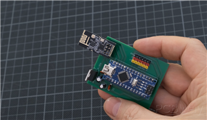
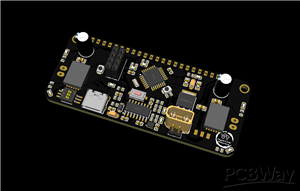
The Homemade Smartwatch is a wearable device featuring a sleek design and customizable functionality. Powered by an Arduino-compatible microcontroller, this smartwatch incorporates an OLED display for a clear and crisp interface, along with sensors and buttons for user interaction. Its modular approach makes it suitable for anyone looking to explore wearable technology.
Key Features
- OLED Display: A vibrant and energy-efficient 0.96-inch display.
- User Controls: Buttons for easy navigation and functionality control.
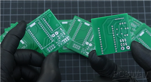
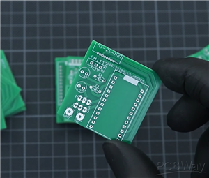
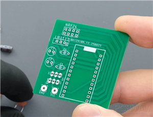
- Compact Design: A custom PCB design and 3D-printed enclosure for a professional look.
- Expandable Functionality: Add sensors or other modules for personalized features.
To help you build this smartwatch, I am sharing the following files:
- Gerber Files: For fabricating the PCB.
- BOM (Bill of Materials): A detailed list of components used in the design.
- Pick-and-Place File: For automated assembly.
- Arduino Code: The complete firmware to bring your smartwatch to life.
How It Works
The smartwatch is based on a microcontroller that handles inputs from buttons and processes data to display on the OLED screen. The PCB design ensures that all components fit perfectly into the 3D-printed enclosure, providing a polished and wearable gadget. You can easily program the microcontroller to add more features such as step counting, notifications, or even weather updates.
Why I Need Your Support
I am participating in PCBWay's 7th Design Contest, and your support can make a huge difference. By voting for my project, you not only recognize the effort behind this smartwatch but also motivate me to create and share more innovative DIY projects.
I invite you to check out the complete tutorial and download all necessary resources to build your own Homemade Smartwatch. Let’s bring this project to life together!
Vote for My Project and Support Me Here!
Thank you for your encouragement, and happy making!
#include <Wire.h>
#include <Adafruit_GFX.h>
#include <Adafruit_SSD1306.h>
#include <Adafruit_SHTC3.h>

// Define OLED display size
#define SCREEN_WIDTH 128
#define SCREEN_HEIGHT 32
#define OLED_RESET    -1
Adafruit_SSD1306 display(SCREEN_WIDTH, SCREEN_HEIGHT, &Wire, OLED_RESET);

Adafruit_SHTC3 shtc3; // SHTC3 sensor object

// Include converted XBM images
#include "temp_icon.xbm"
#include "humidity_icon.xbm"

bool showTemperature = true; // Toggle flag for display switching
float temperature = 0, humidity = 0;

void setup() {
    Serial.begin(115200);

    // Initialize OLED
    if (!display.begin(SSD1306_SWITCHCAPVCC, 0x3C)) {
        Serial.println(F("SSD1306 allocation failed"));
        for (;;);
    }
    display.clearDisplay();

    // Initialize SHTC3 sensor
    if (shtc3.begin()) {
        Serial.println("SHTC3 sensor found");
    } else {
        Serial.println("SHTC3 sensor not detected!");
        while (1);
    }
}

void loop() {
    // Update sensor data
    sensors_event_t humidityEvent, tempEvent;
    shtc3.getEvent(&humidityEvent, &tempEvent);
    temperature = tempEvent.temperature;
    humidity = humidityEvent.relative_humidity;

    display.clearDisplay();

    if (showTemperature) {
        // Show temperature with thermometer icon
        display.drawBitmap(0, 0, temp_icon_bits, 32, 32, SSD1306_WHITE);
        display.setCursor(40, 10);
        display.setTextSize(2);
        display.setTextColor(SSD1306_WHITE);
        display.print(temperature, 1);
        display.println("C");
    } else {
        // Show humidity with percentage & droplet icon
        display.drawBitmap(0, 0, humidity_icon_bits, 32, 32, SSD1306_WHITE);
        display.setCursor(40, 10);
        display.setTextSize(2);
        display.setTextColor(SSD1306_WHITE);
        display.print(humidity, 1);
        display.println("%");
    }

    display.display();

    showTemperature = !showTemperature; // Toggle display
    delay(2000); // Wait 2 seconds
}

DIY low cost Smart watch
*PCBWay community is a sharing platform. We are not responsible for any design issues and parameter issues (board thickness, surface finish, etc.) you choose.


Raspberry Pi 5 7 Inch Touch Screen IPS 1024x600 HD LCD HDMI-compatible Display for RPI 4B 3B+ OPI 5 AIDA64 PC Secondary Screen(Without Speaker)
BUY NOW


- Comments(1)
- Likes(2)
More by Nirmal Maa
-
 VC-02 Module Based Home Automation
In this guide, I’ll take you through the process of building a project using a custom-designed PCB, ...
VC-02 Module Based Home Automation
In this guide, I’ll take you through the process of building a project using a custom-designed PCB, ...
-
 PCBWay 12th Anniversary Badge Design
To celebrate the 12th Anniversary of PCBWay, I designed a special interactive electronic badge that ...
PCBWay 12th Anniversary Badge Design
To celebrate the 12th Anniversary of PCBWay, I designed a special interactive electronic badge that ...
-
 16-Array Line Follower Robot Sensor PCB Design
This project presents a purpose-built 16-channel line follower sensor PCB engineered for precision r...
16-Array Line Follower Robot Sensor PCB Design
This project presents a purpose-built 16-channel line follower sensor PCB engineered for precision r...
-
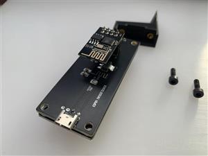 ESP01 + TM1637 NTP Clock (0.56″ 7-Segment Display)
This project is a minimalist Wi-Fi desk clock built around the ESP-01 / ESP-01S and a 0.56″ TM1637 7...
ESP01 + TM1637 NTP Clock (0.56″ 7-Segment Display)
This project is a minimalist Wi-Fi desk clock built around the ESP-01 / ESP-01S and a 0.56″ TM1637 7...
-
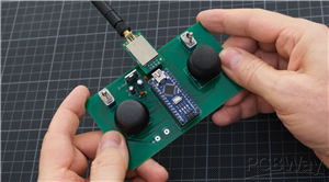 Wireless Dual-Joystick NRF24 Controller PCB for Robotics & RC Applications
This project presents a compact and reliable dual-joystick wireless controller PCB, designed for rob...
Wireless Dual-Joystick NRF24 Controller PCB for Robotics & RC Applications
This project presents a compact and reliable dual-joystick wireless controller PCB, designed for rob...
-
 Channel RC Receiver PCB (NRF24 + Arduino Nano)
This receiver board is the compact, reliable counterpart to the 6-channel transmitter, designed to d...
Channel RC Receiver PCB (NRF24 + Arduino Nano)
This receiver board is the compact, reliable counterpart to the 6-channel transmitter, designed to d...
-
 Compact 3×3 Streaming Macro Pad with RGB & Encoders
The TriPad Studio Controller is a professional-grade 3×3 macro pad designed specifically for streame...
Compact 3×3 Streaming Macro Pad with RGB & Encoders
The TriPad Studio Controller is a professional-grade 3×3 macro pad designed specifically for streame...
-
 Servo & ESC Tester with End-Point Adjustment – (Dual Supply / High-Power)
The Servo & ESC Tester PCB (Dual Supply Version) is designed for applications involving high-tor...
Servo & ESC Tester with End-Point Adjustment – (Dual Supply / High-Power)
The Servo & ESC Tester PCB (Dual Supply Version) is designed for applications involving high-tor...
-
 Servo & ESC Tester with End-Point Adjustment – Single Supply
This Servo & ESC Tester PCB (Single Supply Version) is designed as a compact and reliable tool f...
Servo & ESC Tester with End-Point Adjustment – Single Supply
This Servo & ESC Tester PCB (Single Supply Version) is designed as a compact and reliable tool f...
-
 FPV Head Tracking System – Transmitter PCB
The Transmitter PCB is the sensing and data-sending side of the FPV head tracking system, designed t...
FPV Head Tracking System – Transmitter PCB
The Transmitter PCB is the sensing and data-sending side of the FPV head tracking system, designed t...
-
 FPV Head Tracking System – Receiver PCB (Small Version)
The Small Receiver PCB is the compact counterpart of the FPV head tracking system receiver, designed...
FPV Head Tracking System – Receiver PCB (Small Version)
The Small Receiver PCB is the compact counterpart of the FPV head tracking system receiver, designed...
-
 FPV Head Tracking System – Receiver PCB (Large Version)
This Large Receiver PCB is a core part of a DIY FPV head tracking system, designed to receive head m...
FPV Head Tracking System – Receiver PCB (Large Version)
This Large Receiver PCB is a core part of a DIY FPV head tracking system, designed to receive head m...
-
 N20 Motor Breakout with DRV8212 4A Driver
This N20 Motor Breakout is a compact, motor-mounted driver board built around the DRV8212 H-bridge m...
N20 Motor Breakout with DRV8212 4A Driver
This N20 Motor Breakout is a compact, motor-mounted driver board built around the DRV8212 H-bridge m...
-
 Compact Motion Controller for Competitive Robotics
HMotion is a purpose-built controller PCB designed to simplify and strengthen robotics projects wher...
Compact Motion Controller for Competitive Robotics
HMotion is a purpose-built controller PCB designed to simplify and strengthen robotics projects wher...
-
 LM723 Solar Charge Controller with Voltage & Current Control
This project demonstrates a high-power solar charge controller built around the classic LM723 voltag...
LM723 Solar Charge Controller with Voltage & Current Control
This project demonstrates a high-power solar charge controller built around the classic LM723 voltag...
-
 Transformerless Adjustable AC-to-DC LED Driver (220V AC → 3V–110V DC)
This project explores a transformerless, auto-adjustable LED driver designed to convert 220V AC main...
Transformerless Adjustable AC-to-DC LED Driver (220V AC → 3V–110V DC)
This project explores a transformerless, auto-adjustable LED driver designed to convert 220V AC main...
-
 Adjustable 3.7V Step-Up Boost Converter (5V–30V)
This project presents a compact and efficient step-up boost converter designed to generate higher vo...
Adjustable 3.7V Step-Up Boost Converter (5V–30V)
This project presents a compact and efficient step-up boost converter designed to generate higher vo...
-
 60A Brushless BLDC Motor Controller (ESC)
This project showcases a DIY 60A Brushless DC (BLDC) Motor Controller (ESC) built using N-channel MO...
60A Brushless BLDC Motor Controller (ESC)
This project showcases a DIY 60A Brushless DC (BLDC) Motor Controller (ESC) built using N-channel MO...
-
Programmable Mist Maker - XIAO / QT PY Extension
172 0 0 -
RadioHAT - Raspberry Pi radio development platform
182 0 1 -
-
-
-
-
ARPS-2 – Arduino-Compatible Robot Project Shield for Arduino UNO
2768 0 5 -
A Compact Charging Breakout Board For Waveshare ESP32-C3
3276 3 8 -
AI-driven LoRa & LLM-enabled Kiosk & Food Delivery System
3531 2 2


