


|
arduino IDEArduino
|
Tim's Low Ohms Resistance Meter
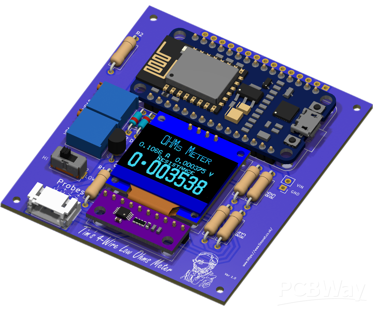
🔧 Tim’s 4‑Wire Low‑Ohms Resistance Meter
A precision Kelvin‑probe instrument using an ESP8266, ADS1115, and a custom motherboard.
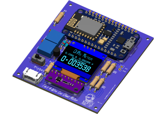
This project is a compact, high‑accuracy 4‑wire (Kelvin) low‑ohms meter designed for measuring resistances from milliohms up to several ohms with excellent stability. It uses an ADS1115 16‑bit ADC, a precision current source, and an ESP8266 to provide both a local OLED display and a full real‑time web interface over Wi‑Fi.
✨ Features
True 4‑wire Kelvin measurement
Precision current source (100 mA / 10 mA ranges)
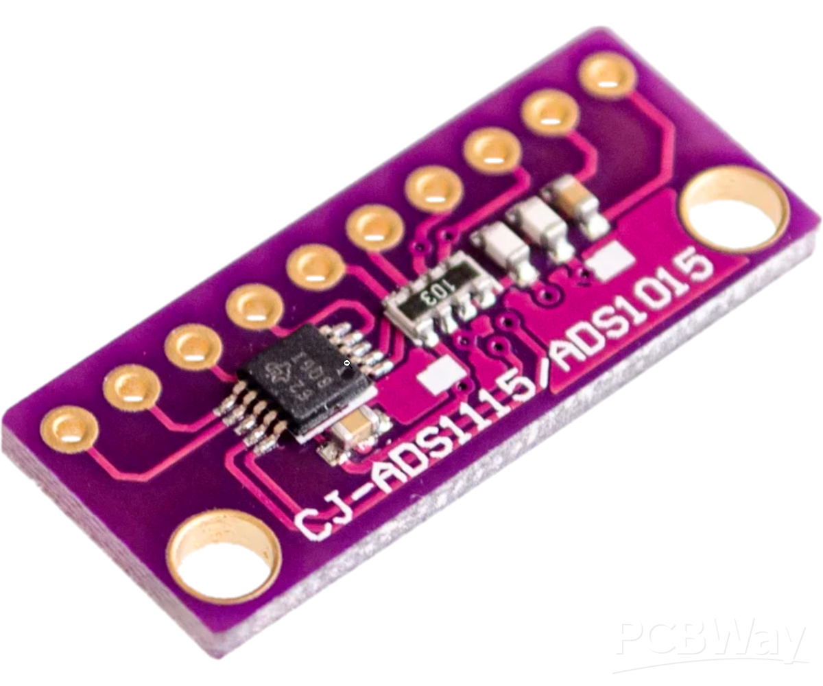
ADS1115 differential measurement for high resolution
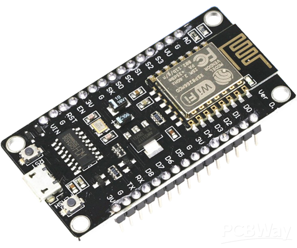
ESP8266 Wi‑Fi connectivity
Real‑time web dashboard with graphs and averaging
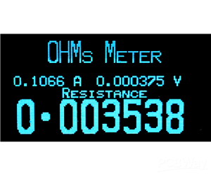
Local OLED display
Calibration mode for shunt accuracy
Configurable OLED pinout using solder jumpers
Low‑profile or socketed assembly options
Open‑source firmware and documentation
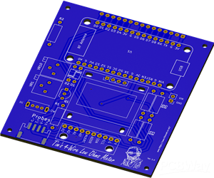
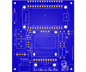
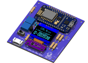
The custom PCB is the core of the instrument. It provides:
Correct Kelvin routing
Stable current‑source geometry
Clean module placement
Reduced wiring noise
A compact, professional layout
There is a full Instructable:
https://www.instructables.com/Tims-Precision-4Wire-LowResistance-Meter/
All components used on the PCB are standard modules:
ESP8266 NodeMCU
ADS1115 ADC module
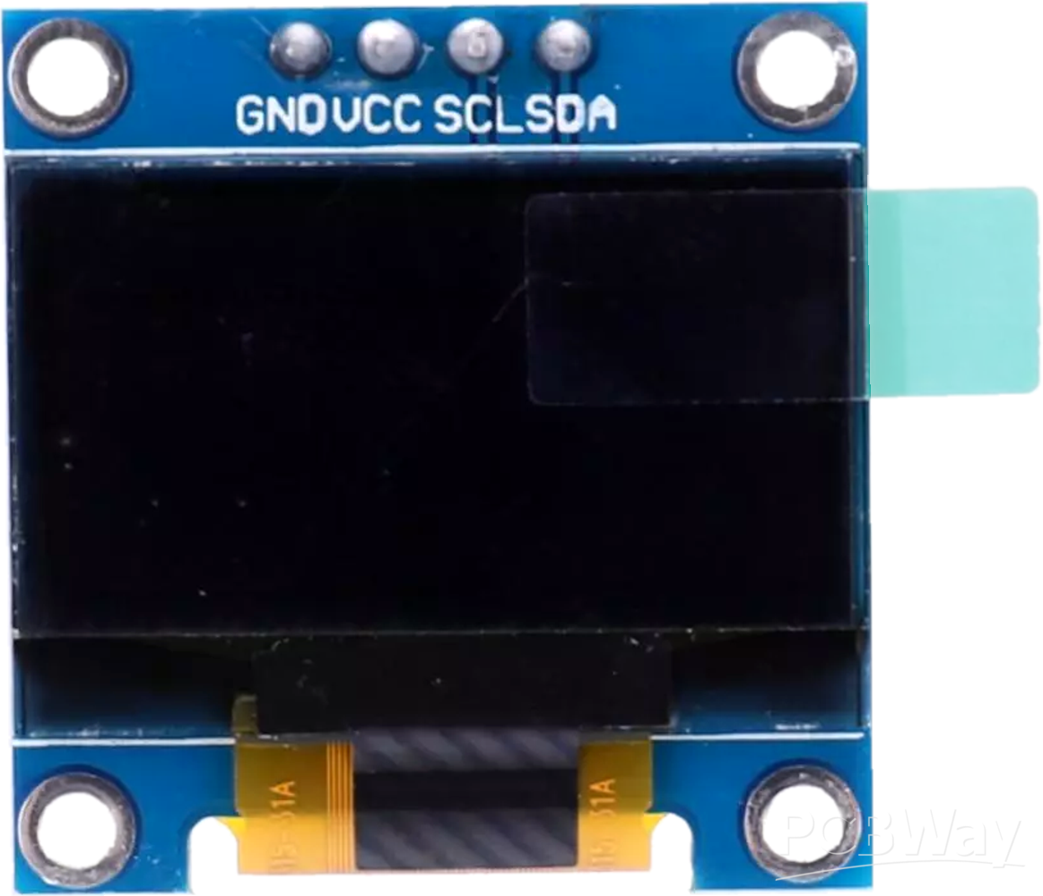
0.96" I²C OLED
Range switch
Precision shunt resistor (R1)
Kelvin probe connector
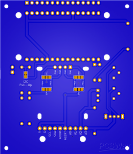
🖥️ OLED Pinout Compatibility (Solder Jumpers)
OLED modules from different suppliers often use different pin orders:
GND and VCC swapped
SDA and SCL swapped
All four pins rearranged
To ensure compatibility, each OLED pin is routed through a 3‑pad solder jumper.
You simply bridge the correct pads to match your OLED’s pinout.
This prevents accidental reverse‑power damage and makes the board future‑proof.
📐 Measurement Overview
The PCB handles all routing internally:
I²C bus shared between ADS1115 and OLED
Differential ADS1115 inputs for DUT voltage and shunt voltage
Current source feeding the DUT through TP1/TP4
Sense lines connected directly across the DUT via TP2/TP3
Range switch selecting 100 mA or 10 mA
No external wiring is required beyond the Kelvin probe connector.
🧮 How the Measurement Works
The meter uses a precision current source, a differential ADC, and Ohm’s Law:
R = V_DUT / I
Where:
V_DUT is measured between TP2 and TP3
I is calculated from the voltage across the shunt resistor R1
The firmware continuously samples both values, applies averaging, and updates:
The OLED
The web interface
The live graph
🎛️ Calibration
To achieve instrument‑grade accuracy, the value of the shunt resistor (R1) must be calibrated.
Enable calibration mode in the firmware
Insert an ammeter in series with the DUT
Read the actual current
Read the shunt voltage from the OLED
Compute:
R1 = V_shunt / I_actual
Update CURRENT_SHUNT_R1 in the firmware
Disable calibration mode and re‑upload
Calibration only needs to be done once unless R1 is changed.
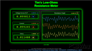
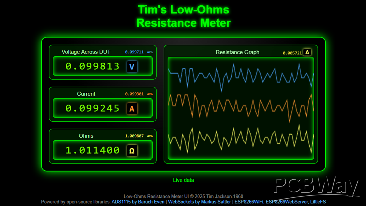
🌐 Wi‑Fi and Web Interface
On boot, the ESP8266 connects to your Wi‑Fi network.
The IP address is shown in the Serial Monitor at 115200 baud.
The web interface provides:
Live voltage, current, and resistance
Averaging
Real‑time graph
Low‑latency updates via WebSockets
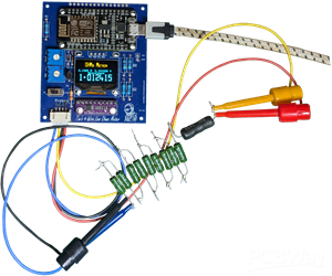
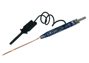
🔌 Kelvin Probe Usage
The instrument uses four probes:
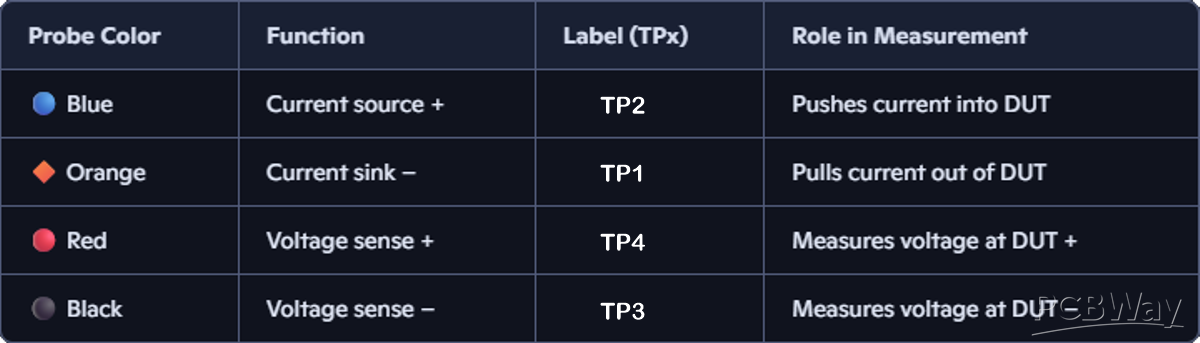
This eliminates lead resistance and contact errors, enabling accurate milliohm measurements.
🛠️ Assembly Options
Option A — Socketed Modules
- Use female headers
- Modules plug in and are replaceable
- Beginner‑friendly
Option B — Low‑Profile Build
- Solder modules directly using pin headers
- Compact, rigid, professional
- This is the version shown in the images
- Both methods work perfectly.
Tim's Low Ohms Resistance Meter
Project images are for reference only. Actual production is based on the manufacturing files on the project page.
Please review the designer's notes (e.g., PCB thickness) and select the appropriate options.
PCBWay is not responsible
for issues caused by unsuitable parameter selections.
For more important ordering information, please refer to
Read More


Raspberry Pi 5 7 Inch Touch Screen IPS 1024x600 HD LCD HDMI-compatible Display for RPI 4B 3B+ OPI 5 AIDA64 PC Secondary Screen(Without Speaker)
BUY NOW


- Comments(0)
- Likes(0)
More by Tim Jackson
-
 Tim's Solar Motor Driver
This is a little solar DC Motor Driver.It uses two LDR (Light Dependant Resistor) sensors to track t...
Tim's Solar Motor Driver
This is a little solar DC Motor Driver.It uses two LDR (Light Dependant Resistor) sensors to track t...
-
 Tim's Low Ohms Resistance Meter
Tim’s 4‑Wire Low‑Ohms Resistance MeterA precision Kelvin‑probe instrument using an ESP8266, ADS1115,...
Tim's Low Ohms Resistance Meter
Tim’s 4‑Wire Low‑Ohms Resistance MeterA precision Kelvin‑probe instrument using an ESP8266, ADS1115,...
-
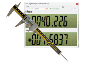 Tim's Digital Calliper Interface
️ Build a USB Digital Calliper Interface with STM8SFeaturing a Fractional Inch Display App — Availab...
Tim's Digital Calliper Interface
️ Build a USB Digital Calliper Interface with STM8SFeaturing a Fractional Inch Display App — Availab...
-
 Tim's 7555 Signal Injector
There is not much to say about this little tool.It started as a challenge made by Richard at "Learn ...
Tim's 7555 Signal Injector
There is not much to say about this little tool.It started as a challenge made by Richard at "Learn ...
-
 Tim's Servo Tester
IntroductionThere are plenty of cheap servo testers on the market — and for basic tasks, they work w...
Tim's Servo Tester
IntroductionThere are plenty of cheap servo testers on the market — and for basic tasks, they work w...
-
 Tim's Edison Blue Amberol Record Player
This board is for controlling the "Tim's Edison Blue Amberol Record Player" Project.I have put full ...
Tim's Edison Blue Amberol Record Player
This board is for controlling the "Tim's Edison Blue Amberol Record Player" Project.I have put full ...
-
 Tim's DFPlayer Plus Box
This is a box I designed to hold Tim's DFPlayer Plus that I have shared here:...
Tim's DFPlayer Plus Box
Tim's DFPlayer Plus BoxThis is a box I designed to hold Tim's DFPlayer Plus that I have shared here:...
-
 Tim's DFPlayer Plus
This project was inspired by one of my favourite YouTube channels.I mention them in my first video f...
Tim's DFPlayer Plus
This project was inspired by one of my favourite YouTube channels.I mention them in my first video f...
-
 Tim's I2C Dual Motor Driver [Version 2]
This is Version 2 of my previous Tim's I2C Dual Motor Driver.This supersedes this Project. Tim's I2C...
Tim's I2C Dual Motor Driver [Version 2]
This is Version 2 of my previous Tim's I2C Dual Motor Driver.This supersedes this Project. Tim's I2C...
-
 Tim's Mini Plotter 2
This is a PCBWay PCB Version of mini plotter I did quit a while ago, my original mini plotter I made...
Tim's Mini Plotter 2
This is a PCBWay PCB Version of mini plotter I did quit a while ago, my original mini plotter I made...
-
 Tim's I2C Dual Motor Driver
This board has been SupersededThe version 2 can be found here:Tim's I2C Dual Motor Driver [Version ...
Tim's I2C Dual Motor Driver
This board has been SupersededThe version 2 can be found here:Tim's I2C Dual Motor Driver [Version ...
-
 Tim's Pie Divider
When that pie comes out of the oven and your tummy rumbles, who gets the largest pi...
Tim's Pie Divider
Tim's Pie DividerWhen that pie comes out of the oven and your tummy rumbles, who gets the largest pi...
-
 Tim's I2C Intelligent DC Motor Driver
I am working on a project that needs about six Motors. There are many DC Motor Drivers available, Bu...
Tim's I2C Intelligent DC Motor Driver
I am working on a project that needs about six Motors. There are many DC Motor Drivers available, Bu...
-
 Tim's PTC Hot Plate Controller [Fused version]
This is a fused version of this: Tim's PTC Hot Plate ControllerInstructable at: Tim's Hot PlateFor c...
Tim's PTC Hot Plate Controller [Fused version]
This is a fused version of this: Tim's PTC Hot Plate ControllerInstructable at: Tim's Hot PlateFor c...
-
 Tim's PTC Hot Plate Controller
This is a for a DIY Hot Plate, for soldering SMD to PCBs.The heater element that it controls are the...
Tim's PTC Hot Plate Controller
This is a for a DIY Hot Plate, for soldering SMD to PCBs.The heater element that it controls are the...
-
 TIM-01 EYES
This is a module to give my robot TIM-01 Eyes.With many projects controlled by an Arduino or similar...
TIM-01 EYES
This is a module to give my robot TIM-01 Eyes.With many projects controlled by an Arduino or similar...
-
 Tim's DC Motor Driver X6 Mk2
This board was designed to drive the motors controlling the arms on my robot TIM-01.I have a blog on...
Tim's DC Motor Driver X6 Mk2
This board was designed to drive the motors controlling the arms on my robot TIM-01.I have a blog on...
-
Programmable Mist Maker - XIAO / QT PY Extension
1054 2 1 -
RadioHAT - Raspberry Pi radio development platform
850 0 2 -
-
-
-
-
ARPS-2 – Arduino-Compatible Robot Project Shield for Arduino UNO
3316 0 6 -
A Compact Charging Breakout Board For Waveshare ESP32-C3
3920 3 8 -
AI-driven LoRa & LLM-enabled Kiosk & Food Delivery System
4309 2 2


