


Tim's Solar Motor Driver
This is a little solar DC Motor Driver.
It uses two LDR (Light Dependant Resistor) sensors to track the movement of the sun.
There is no microcontroller, it uses an Op-Amp (Operational Amplifier) as a comparator to switch relays to drive a motor.
With the correct rated relays A Large DC Motor can be driven.
I totally messed up in the video above trying to explain the Logic Gates off the top of my head, due to my memory issues (it is what it is).
You may want to watch the video below first, so that you know where to skip through my video above.
The working voltage of this PCB is 5 volts.
The main components I used in this project where parts I had in my box of bits.
I don't think it is critical that you use the exact parts that I have used.
Some Adjustment may be required based on your location and the amount of sun you get.
The DC Motor driver is based around voltage dividers and the result processed by the Op-Amp used as a comparator.
The reference voltage is set by resistors R1 and R2. Changing R2 can make it more sensitive to changes in light.
R2 can be 4.7k to 10k.
There is a socket for attaching remote LDRs. Using the onboard LDRs requires the solder jumpers to be connected.
There is an onboard 5 volt linear regulator, this can supply the working voltage from the motor power, via a solder jumper.
Note! The linear regulator has a max input voltage. If your motor power exceeds this the a separate 5 volt supply will be needed.
There is a BOM in the zip file, below I have made some notes about the main components.
LDR

I find LDR (Light Dependant Resistor) can be quite hit and miss.
The ones I have used are for my old stock of parts, I have no clue to the make or specification.
The resistance when Dark is around 1M. (cover with black card)
The resistance in use is around 1k to 20k.
To balance the voltage divider we want about 10k in ambient light, so it equals the reference voltage. Pointing at the sunlight it should change from this.
Op-Amp

I have used a NE5532B (over 2000 gain, a little over the top) Operational Amplifier as a comparator.
Any compatible Op-Amp should do.
Vcc is 5 volts.
All it needs to output is below and above the threshold of the Logic Gate.
NOR Gates

I have used the CD4001B Quad 2 input NOR chip, I use 3 of the gates.
Any compatible with 5 volts should be ok to use.
Relay SPDT

The relay I have used is the type you get in Arduino kits.
It needs to have a 5 volts coil.
It needs to be SPDT (Single Pole, Double Throw).
The rating of the contacts should be able to handle the motor used.
The circuit

Me assembling the components
Assembled

Does it Work
Tim's Solar Motor Driver
Project images are for reference only. Actual production is based on the manufacturing files on the project page.
Please review the designer's notes (e.g., PCB thickness) and select the appropriate options.
PCBWay is not responsible
for issues caused by unsuitable parameter selections.
For more important ordering information, please refer to
Read More


Raspberry Pi 5 7 Inch Touch Screen IPS 1024x600 HD LCD HDMI-compatible Display for RPI 4B 3B+ OPI 5 AIDA64 PC Secondary Screen(Without Speaker)
BUY NOW


- Comments(0)
- Likes(0)
More by Tim Jackson
-
 Tim's Solar Motor Driver
This is a little solar DC Motor Driver.It uses two LDR (Light Dependant Resistor) sensors to track t...
Tim's Solar Motor Driver
This is a little solar DC Motor Driver.It uses two LDR (Light Dependant Resistor) sensors to track t...
-
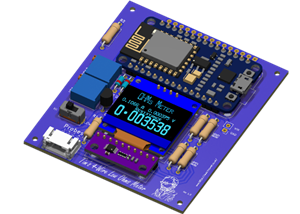 Tim's Low Ohms Resistance Meter
Tim’s 4‑Wire Low‑Ohms Resistance MeterA precision Kelvin‑probe instrument using an ESP8266, ADS1115,...
Tim's Low Ohms Resistance Meter
Tim’s 4‑Wire Low‑Ohms Resistance MeterA precision Kelvin‑probe instrument using an ESP8266, ADS1115,...
-
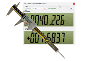 Tim's Digital Calliper Interface
️ Build a USB Digital Calliper Interface with STM8SFeaturing a Fractional Inch Display App — Availab...
Tim's Digital Calliper Interface
️ Build a USB Digital Calliper Interface with STM8SFeaturing a Fractional Inch Display App — Availab...
-
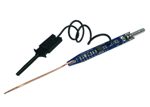 Tim's 7555 Signal Injector
There is not much to say about this little tool.It started as a challenge made by Richard at "Learn ...
Tim's 7555 Signal Injector
There is not much to say about this little tool.It started as a challenge made by Richard at "Learn ...
-
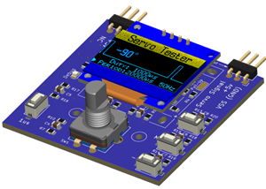 Tim's Servo Tester
IntroductionThere are plenty of cheap servo testers on the market — and for basic tasks, they work w...
Tim's Servo Tester
IntroductionThere are plenty of cheap servo testers on the market — and for basic tasks, they work w...
-
 Tim's Edison Blue Amberol Record Player
This board is for controlling the "Tim's Edison Blue Amberol Record Player" Project.I have put full ...
Tim's Edison Blue Amberol Record Player
This board is for controlling the "Tim's Edison Blue Amberol Record Player" Project.I have put full ...
-
 Tim's DFPlayer Plus Box
This is a box I designed to hold Tim's DFPlayer Plus that I have shared here:...
Tim's DFPlayer Plus Box
Tim's DFPlayer Plus BoxThis is a box I designed to hold Tim's DFPlayer Plus that I have shared here:...
-
 Tim's DFPlayer Plus
This project was inspired by one of my favourite YouTube channels.I mention them in my first video f...
Tim's DFPlayer Plus
This project was inspired by one of my favourite YouTube channels.I mention them in my first video f...
-
 Tim's I2C Dual Motor Driver [Version 2]
This is Version 2 of my previous Tim's I2C Dual Motor Driver.This supersedes this Project. Tim's I2C...
Tim's I2C Dual Motor Driver [Version 2]
This is Version 2 of my previous Tim's I2C Dual Motor Driver.This supersedes this Project. Tim's I2C...
-
 Tim's Mini Plotter 2
This is a PCBWay PCB Version of mini plotter I did quit a while ago, my original mini plotter I made...
Tim's Mini Plotter 2
This is a PCBWay PCB Version of mini plotter I did quit a while ago, my original mini plotter I made...
-
 Tim's I2C Dual Motor Driver
This board has been SupersededThe version 2 can be found here:Tim's I2C Dual Motor Driver [Version ...
Tim's I2C Dual Motor Driver
This board has been SupersededThe version 2 can be found here:Tim's I2C Dual Motor Driver [Version ...
-
 Tim's Pie Divider
When that pie comes out of the oven and your tummy rumbles, who gets the largest pi...
Tim's Pie Divider
Tim's Pie DividerWhen that pie comes out of the oven and your tummy rumbles, who gets the largest pi...
-
 Tim's I2C Intelligent DC Motor Driver
I am working on a project that needs about six Motors. There are many DC Motor Drivers available, Bu...
Tim's I2C Intelligent DC Motor Driver
I am working on a project that needs about six Motors. There are many DC Motor Drivers available, Bu...
-
 Tim's PTC Hot Plate Controller [Fused version]
This is a fused version of this: Tim's PTC Hot Plate ControllerInstructable at: Tim's Hot PlateFor c...
Tim's PTC Hot Plate Controller [Fused version]
This is a fused version of this: Tim's PTC Hot Plate ControllerInstructable at: Tim's Hot PlateFor c...
-
 Tim's PTC Hot Plate Controller
This is a for a DIY Hot Plate, for soldering SMD to PCBs.The heater element that it controls are the...
Tim's PTC Hot Plate Controller
This is a for a DIY Hot Plate, for soldering SMD to PCBs.The heater element that it controls are the...
-
 TIM-01 EYES
This is a module to give my robot TIM-01 Eyes.With many projects controlled by an Arduino or similar...
TIM-01 EYES
This is a module to give my robot TIM-01 Eyes.With many projects controlled by an Arduino or similar...
-
 Tim's DC Motor Driver X6 Mk2
This board was designed to drive the motors controlling the arms on my robot TIM-01.I have a blog on...
Tim's DC Motor Driver X6 Mk2
This board was designed to drive the motors controlling the arms on my robot TIM-01.I have a blog on...
-
Programmable Mist Maker - XIAO / QT PY Extension
1089 2 1 -
RadioHAT - Raspberry Pi radio development platform
910 0 2 -
-
-
-
-
ARPS-2 – Arduino-Compatible Robot Project Shield for Arduino UNO
3344 0 6 -
A Compact Charging Breakout Board For Waveshare ESP32-C3
3959 3 8 -
AI-driven LoRa & LLM-enabled Kiosk & Food Delivery System
4344 2 2


