


|
|
ESP32-WROOM-32E-N4ESPRESSIF(乐鑫)
|
x 1 | |
|
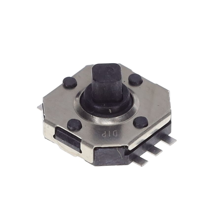
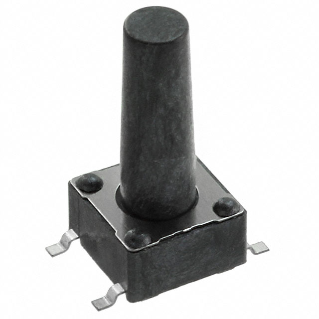
TSSJ 5Knitter-Switch
|
x 1 | |
|
430182130816Würth Elektronik
|
x 1 | |
|
|
RS485 |
x 1 | |
|
|
MICRO USB B |
x 1 |

|
arduino IDEArduino
|
|
|
|
INAV Configurator |
|
|
|
BETAFLIGHT Configurator |
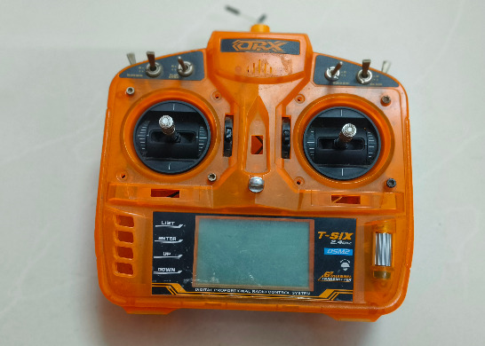
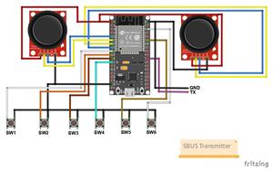
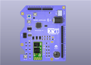
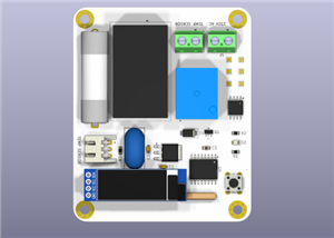
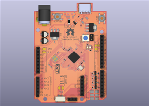
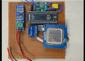
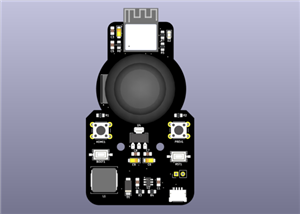
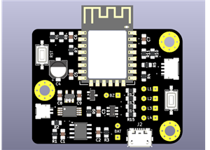
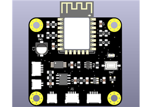
SBUS-Transmitter Made with ESP32
This centroid file is an approximate pick-and-place reference created for early PCB planning of your ESP32 SBUS transmitter using an ESP32 development board and a MAX485 RS485 interface. All coordinates are assumed in millimeters, referenced from the bottom-left PCB origin, with components placed on the top layer only. The ESP32 dev board is treated as a single module, while discrete parts such as the MAX485, resistors, capacitors, switches, and connectors are positioned logically around it for routing feasibility and assembly clarity.
This data is not intended for final automated assembly and should not be used directly for manufacturing without verification. Exact centroid positions, rotations, and package definitions must be generated from your PCB CAD tool (KiCad) once footprints and board outline are finalized. Use this file strictly for conceptual validation, BOM correlation, and early mechanical planning before locking the design.
#include <Arduino.h>
// Use UART2 on ESP32//TX2 OF ESP32 WITH A3 OF BLACK PILL
HardwareSerial SBUS(2);

// ---------------- SBUS SETTINGS ----------------
#define SBUS_TX_PIN 17
#define SBUS_CHANNELS 16
#define SBUS_PACKET_LEN 25
#define SBUS_MIN 173
#define SBUS_MAX 1811
#define HEADER 0x0F
#define FOOTER 0x00
const int SBUS_RATE = 15;  // 15 ms

uint16_t rc[SBUS_CHANNELS];
uint8_t packet[SBUS_PACKET_LEN];
unsigned long lastSend = 0;

// ---------------- INPUT PINS ----------------
// Joysticks
const int JOY1_X_PIN = 32;
const int JOY1_Y_PIN = 35;
const int JOY2_X_PIN = 34;
const int JOY2_Y_PIN = 33;

// 6 Switches
const int SW1_PIN = 25;
const int SW2_PIN = 26;
const int SW3_PIN = 27;
const int SW4_PIN = 14;
const int SW5_PIN = 21;
const int SW6_PIN = 22;

// ---------------- SBUS PACKET CREATOR ----------------
void createPacket() {
  uint16_t ch[SBUS_CHANNELS];
  for (int i = 0; i < SBUS_CHANNELS; i++)
    ch[i] = map(rc[i], 1000, 2000, SBUS_MIN, SBUS_MAX);

  packet[0] = HEADER;
  packet[1] = ch[0] & 0xFF;
  packet[2] = ((ch[0] >> 8) | (ch[1] << 3)) & 0xFF;
  packet[3] = ((ch[1] >> 5) | (ch[2] << 6)) & 0xFF;
  packet[4] = (ch[2] >> 2) & 0xFF;
  packet[5] = ((ch[2] >> 10) | (ch[3] << 1)) & 0xFF;
  packet[6] = ((ch[3] >> 7) | (ch[4] << 4)) & 0xFF;
  packet[7] = ((ch[4] >> 4) | (ch[5] << 7)) & 0xFF;
  packet[8] = (ch[5] >> 1) & 0xFF;
  packet[9] = ((ch[5] >> 9) | (ch[6] << 2)) & 0xFF;
  packet[10] = ((ch[6] >> 6) | (ch[7] << 5)) & 0xFF;
  packet[11] = (ch[7] >> 3) & 0xFF;
  packet[12] = ch[8] & 0xFF;
  packet[13] = ((ch[8] >> 8) | (ch[9] << 3)) & 0xFF;
  packet[14] = ((ch[9] >> 5) | (ch[10] << 6)) & 0xFF;
  packet[15] = (ch[10] >> 2) & 0xFF;
  packet[16] = ((ch[10] >> 10) | (ch[11] << 1)) & 0xFF;
  packet[17] = ((ch[11] >> 7) | (ch[12] << 4)) & 0xFF;
  packet[18] = ((ch[12] >> 4) | (ch[13] << 7)) & 0xFF;
  packet[19] = (ch[13] >> 1) & 0xFF;
  packet[20] = ((ch[13] >> 9) | (ch[14] << 2)) & 0xFF;
  packet[21] = ((ch[14] >> 6) | (ch[15] << 5)) & 0xFF;
  packet[22] = (ch[15] >> 3) & 0xFF;

  packet[23] = 0x00;  // flags
  packet[24] = FOOTER;
}

// ---------------- SETUP ----------------
void setup() {
  SBUS.begin(100000, SERIAL_8E2, -1, SBUS_TX_PIN);
  Serial.begin(115200);
  delay(200);

  pinMode(SW1_PIN, INPUT_PULLUP);
  pinMode(SW2_PIN, INPUT_PULLUP);
  pinMode(SW3_PIN, INPUT_PULLUP);
  pinMode(SW4_PIN, INPUT_PULLUP);
  pinMode(SW5_PIN, INPUT_PULLUP);
  pinMode(SW6_PIN, INPUT_PULLUP);

  for (int i = 0; i < SBUS_CHANNELS; i++)
    rc[i] = 1500;
}

// ---------------- LOOP ----------------
void loop() {
  if (millis() - lastSend >= SBUS_RATE) {
    lastSend = millis();

// ---- Read Joysticks (ADC) ----
// ---- Read Joysticks (ADC) ----

// CH0 = JOY2_X
rc[0] = map(analogRead(JOY2_X_PIN), 0, 4095, 1000, 2000);

// CH1 = JOY1_Y (inverted)
rc[1] = map(analogRead(JOY1_Y_PIN), 0, 4095, 2000, 1000);

// CH2 = JOY2_Y   (this was CH3 earlier)
rc[2] = map(analogRead(JOY2_Y_PIN), 0, 4095, 2000, 1000);

// CH3 = JOY1_X   (this was CH2 earlier)
rc[3] = map(analogRead(JOY1_X_PIN), 0, 4095, 1000, 2000);


    // ---- Read Switches (digital) ----
    rc[4] = digitalRead(SW1_PIN) ? 1000 : 2000;
    rc[5] = digitalRead(SW2_PIN) ? 1000 : 2000;
    rc[6] = digitalRead(SW3_PIN) ? 1000 : 2000;
    rc[7] = digitalRead(SW4_PIN) ? 1000 : 2000;
    rc[8] = digitalRead(SW5_PIN) ? 1000 : 2000;
    rc[9] = digitalRead(SW6_PIN) ? 1000 : 2000;

    // Idle for CH10–CH15
    for (int i = 10; i < 16; i++)
      rc[i] = 1500;

    // ----- Serial Monitor Debug Output -----
    Serial.print("CH0(J1_X)=");
    Serial.print(rc[0]);
    Serial.print("  CH1(J1_Y)=");
    Serial.print(rc[1]);
    Serial.print("  CH2(J2_X)=");
    Serial.print(rc[2]);
    Serial.print("  CH3(J2_Y)=");
    Serial.print(rc[3]);

    Serial.print("  SW1(CH4)=");
    Serial.print(rc[4]);
    Serial.print("  SW2(CH5)=");
    Serial.print(rc[5]);
    Serial.print("  SW3(CH6)=");
    Serial.print(rc[6]);
    Serial.print("  SW4(CH7)=");
    Serial.print(rc[7]);
    Serial.print("  SW5(CH8)=");
    Serial.print(rc[8]);
    Serial.print("  SW6(CH9)=");
    Serial.print(rc[9]);
    Serial.println();

    createPacket();
    SBUS.write(packet, SBUS_PACKET_LEN);
  }
}
SBUS-Transmitter Made with ESP32


Raspberry Pi 5 7 Inch Touch Screen IPS 1024x600 HD LCD HDMI-compatible Display for RPI 4B 3B+ OPI 5 AIDA64 PC Secondary Screen(Without Speaker)
BUY NOW


- Comments(1)
- Likes(2)
More by MAATHES THILAK K
-
 BLUDIONO - Arduino Accelerated with Bluetooth Module
This project presents a compact Arduino-compatible SMD development board based on the ATmega328P-AU,...
BLUDIONO - Arduino Accelerated with Bluetooth Module
This project presents a compact Arduino-compatible SMD development board based on the ATmega328P-AU,...
-
 Solder-Master-PRO
is a precision soldering station designed to deliver professional-grade temperature control using a ...
Solder-Master-PRO
is a precision soldering station designed to deliver professional-grade temperature control using a ...
-
 RP2040 Community-Driven UNO MCU
This project expands an RP2040-based, Arduino UNO–style microcontroller designed to stay familiar wh...
RP2040 Community-Driven UNO MCU
This project expands an RP2040-based, Arduino UNO–style microcontroller designed to stay familiar wh...
-
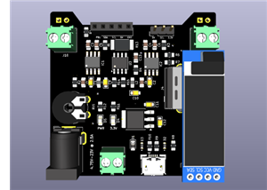
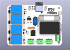 4CH_TIMER_RELAY
This 4-channel relay timer controller is built around the ESP32-C3 microcontroller, offering smart a...
4CH_TIMER_RELAY
This 4-channel relay timer controller is built around the ESP32-C3 microcontroller, offering smart a...
-
 Spray Bot - 3D MODEL
Spray Bot is an intelligent agricultural robot designed to complement Vision Bot by performing targe...
Spray Bot - 3D MODEL
Spray Bot is an intelligent agricultural robot designed to complement Vision Bot by performing targe...
-
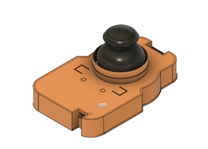 AIR MOUSE CASE
_ is a compact wireless remote mouse built around the ESP32-C3, intended for smart TVs, media center...
AIR MOUSE CASE
_ is a compact wireless remote mouse built around the ESP32-C3, intended for smart TVs, media center...
-
 RS485 based Flight Controller - STM32F411CEU6
This repository documents the design and implementation of a custom STM32F411-based flight controlle...
RS485 based Flight Controller - STM32F411CEU6
This repository documents the design and implementation of a custom STM32F411-based flight controlle...
-
 SBUS-Transmitter Made with ESP32
This centroid file is an approximate pick-and-place reference created for early PCB planning of your...
SBUS-Transmitter Made with ESP32
This centroid file is an approximate pick-and-place reference created for early PCB planning of your...
-
 Attiny85-Powered Mini Oscilloscope
This project presents a compact, cost-effective mini oscilloscope PCB powered by the ATtiny85 microc...
Attiny85-Powered Mini Oscilloscope
This project presents a compact, cost-effective mini oscilloscope PCB powered by the ATtiny85 microc...
-
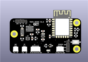
 Water Motor Controller - Twin Node
Project DescriptionThe TWIN-NODE Motor Controller is a compact, wireless motor control PCB designed ...
Water Motor Controller - Twin Node
Project DescriptionThe TWIN-NODE Motor Controller is a compact, wireless motor control PCB designed ...
-
 BENCH_POWER_SUPPLY-PSU
This project presents a compact bench power supply enclosure designed in Autodesk Fusion 360, tailor...
BENCH_POWER_SUPPLY-PSU
This project presents a compact bench power supply enclosure designed in Autodesk Fusion 360, tailor...
-
 AIR_MOUSE – ESP32-C3 Based Wireless Air-Style Remote
The AIR_MOUSE is a compact wireless air-style remote designed for effortless navigation of TVs and o...
AIR_MOUSE – ESP32-C3 Based Wireless Air-Style Remote
The AIR_MOUSE is a compact wireless air-style remote designed for effortless navigation of TVs and o...
-
 Indoor Node - WaterlevelMonitor - Twin Node
The TWIN-NODE Indoor Node is a battery-powered receiver module designed to provide local indication ...
Indoor Node - WaterlevelMonitor - Twin Node
The TWIN-NODE Indoor Node is a battery-powered receiver module designed to provide local indication ...
-
 Twin_Node_V2.0_WaterLevelMonitor
TWIN-NODE is a two-node, ultra-low-power water level monitoring system engineered for overhead tanks...
Twin_Node_V2.0_WaterLevelMonitor
TWIN-NODE is a two-node, ultra-low-power water level monitoring system engineered for overhead tanks...
-
 Twin_Node_V1.0-OUTDOOR
TWIN NODE V1.0 is a low-power, outdoor-ready water level sensor node designed as a practical learnin...
Twin_Node_V1.0-OUTDOOR
TWIN NODE V1.0 is a low-power, outdoor-ready water level sensor node designed as a practical learnin...
-
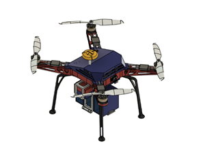
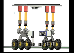 Vision Bot V1 – AI rover with pneumatic
Vision Bot V1 is the latest and fully refined iteration of our agricultural monitoring rover, develo...
Vision Bot V1 – AI rover with pneumatic
Vision Bot V1 is the latest and fully refined iteration of our agricultural monitoring rover, develo...
-
 OverEngineered Bread Board Power supply
Over-Engineered Breadboard Power SupplyThis project is a compact, high-current breadboard power supp...
OverEngineered Bread Board Power supply
Over-Engineered Breadboard Power SupplyThis project is a compact, high-current breadboard power supp...
-
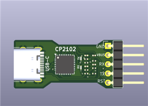 USB to UART Converter Board using CP2102
This project presents a simple and compact USB to UART converter board designed around the CP2102 US...
USB to UART Converter Board using CP2102
This project presents a simple and compact USB to UART converter board designed around the CP2102 US...
-
Programmable Mist Maker - XIAO / QT PY Extension
1061 2 1 -
RadioHAT - Raspberry Pi radio development platform
863 0 2 -
-
-
-
-
ARPS-2 – Arduino-Compatible Robot Project Shield for Arduino UNO
3323 0 6 -
A Compact Charging Breakout Board For Waveshare ESP32-C3
3932 3 8 -
AI-driven LoRa & LLM-enabled Kiosk & Food Delivery System
4319 2 2


