


More Bass Treble and Volume! With PT2313 DSP
When it comes to signal processing through a digital medium then DSPs are the one who comes into play. Basically here we are talking about audio signals and music. In the convention audio system there are analog systems consisting of a lot of opamp drives and knobs to adjust the different settings. A basic analog system may perform well but it is bulky and not realizable in certain places where we want a computer control. On the other hand these DSP units are cheap and easy to configure with a microcontroller.
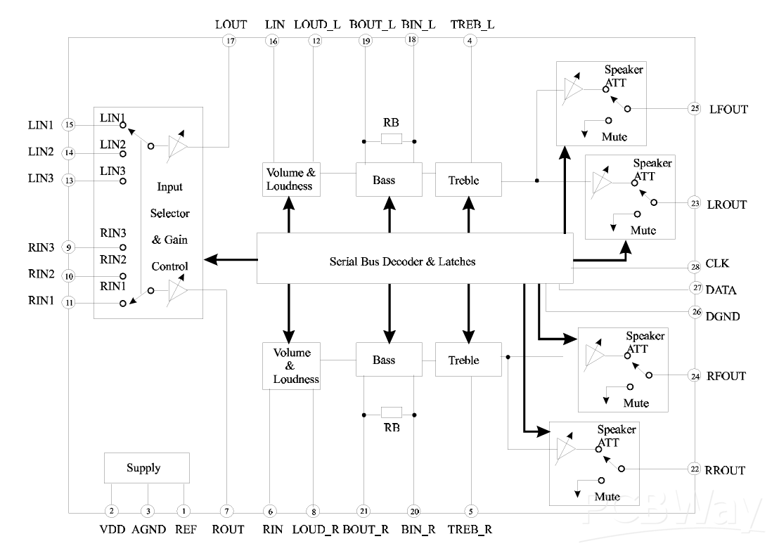
I found the one, it is quite old “PT2313” from Princeton Taiwan. PT2313 is a four-channel digital audio processor utilizing CMOS Technology. Volume, Right/Left Bass and Treble Balance, Front/Rear Fader Processor are incorporated into a single chip. Loudness Function and Selectable Input Gain are also provided to build a highly effective electronic audio processor having the highest performance and reliability with the least external components. All functions are programmable using the Serial Bus. The pin assignments and application circuit are optimized for easy PCB layout and cost saving advantage for audio application.
This PCB is sponsored by PCBWAY. I have ordered the PCBs, because I have been using the services for a long time. PCBWAY is the only well known company which deals in PCB related products. Here you will get fulfilled all the prototyping requirements.
Features of PT2313:
- Least External Components
- Treble and Bass Control
- Loudness Function
- 3 Stereo Inputs with Selectable Input Gain
- Input/Output for External Noise Reduction System/Equalizer
- Controls for Fader and Balance
- Independent Mute Function
- Volume Control in 1.25 dB/step
- Controlled by Serial Bus Micro-Processor Interface
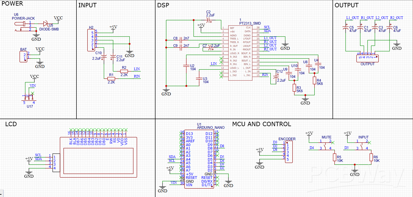
Circuit Diagram:
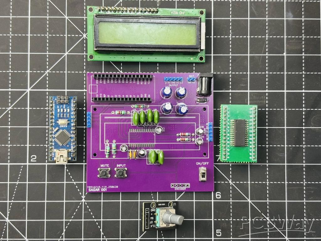
I am using this chip to feed to an amplifier circuit, this chip can be used as a standalone preamplifier circuit. Now because it has 3 inputs, but here I don’t need that much so I am using only one of them. But at the output I am using all 4, in which 2 will not work (reserved for later). So this will be a 2 channel system through which I can control Channel gain, volume, bass, table and balance. Because the system works with I2C we can directly connect a compatible microcontroller like UNO/NANO. Some required components are:
- PT2313 DSP
- 16X2 LCD with I2C
- 5.6K, 10K, 2K2 Resistor
- 100n, 2.7n, 10u, 47u Capacitor
- Encoder Module
- Arduino Nano
- Tactile Switches
The circuit diagram given here is fully tested and designed to minimize the noise, all the digital section is kept away from the signal conditioning part. To avoid noise issues. This has a 16x2 LCD, an Arduino Nano, an Encoder and some resistor for external configuration.
Code for DSP:
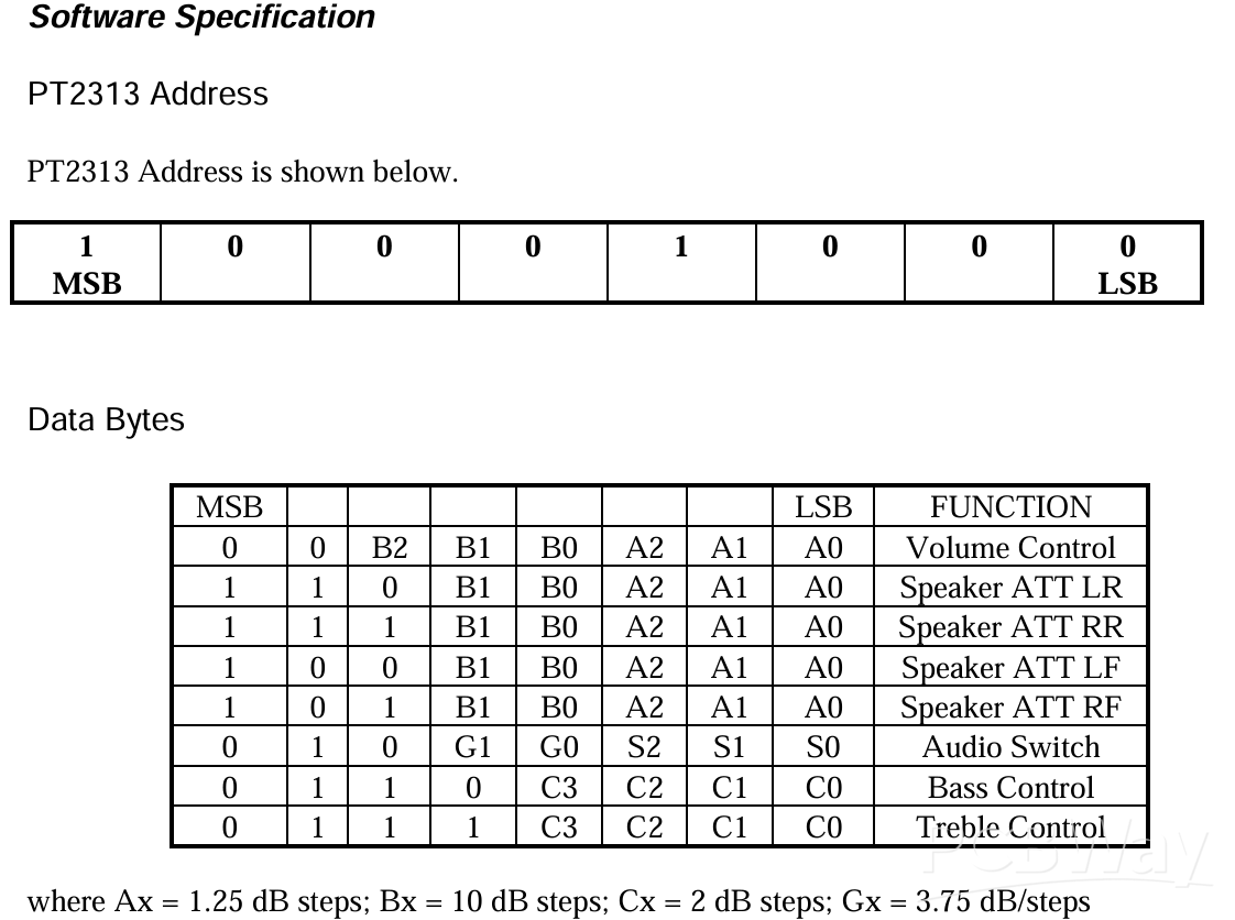
Basically we have pre-made libraries to implement different functions, all of which are designed based on the register information given in the datasheet. For example the one shared below is for a general register map. After programming the register map the location and data is sent through I2C which fills the resistor and changes the output characteristics of the IC. In the next few tutorials we will try to design our own PCBs and libraries but right now using an open source example from the web. Download the datasheet and library from here and code is given below for the same. Library download link: https://drive.google.com/file/d/1NmqZHj--yFQHnVIe1FuU4L_6juC5jjzR/view?usp=sharing
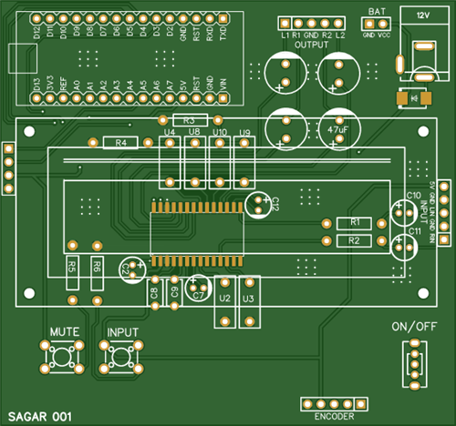
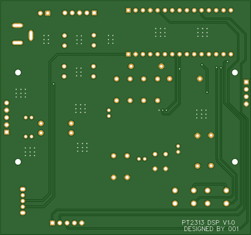
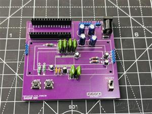
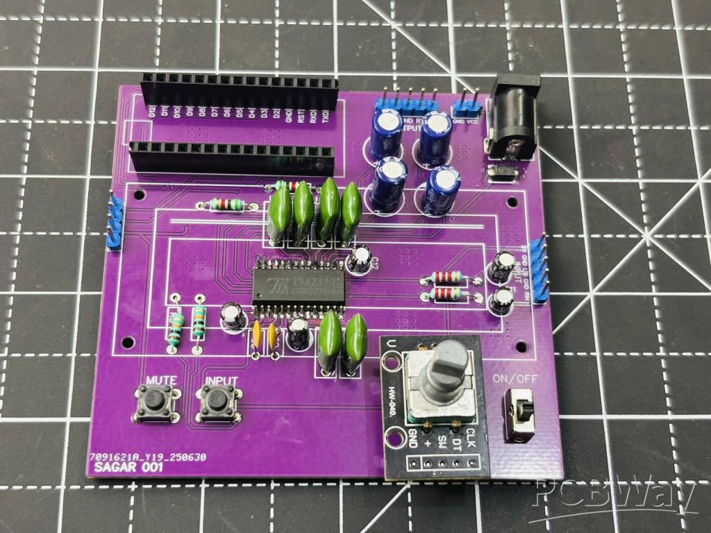
PCB Designs:
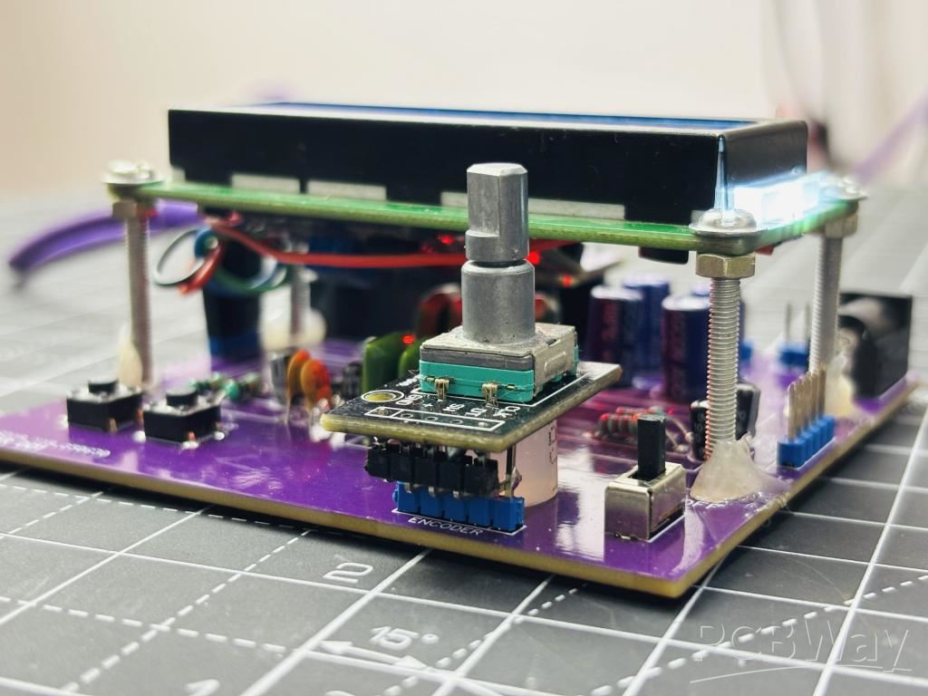
I have designed this PCB, in which I considered signal integrity. The PCB is designed to minimize the crosstalk and noise of the signal. I have put the IC in the middle and external components around it. Because here we are using a 16x2 I2C LCD. It is installed with screws at a little height, so all the DSP part is built under that. Moreover we have Arduino NANO on the top of the board and a DC barrel jack on the opposite side.
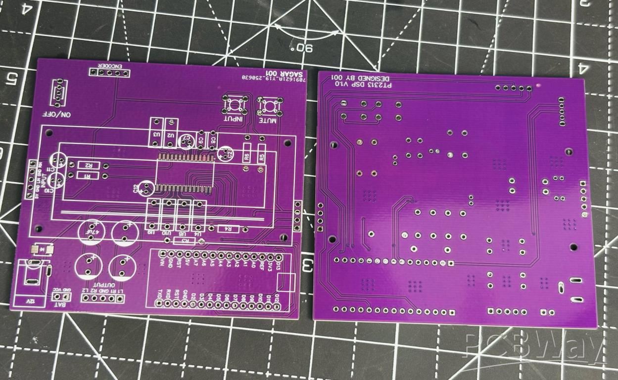
Coming to the control section instead of different potentiometer knobs like the analog system we have only an encoder to select the different values. Which is demonstrated in the next section below. Moreover we have input with a signal conditioning part and output 4 channels (2 reserved) on the top. You can attach any audio source and use the same. We have 2 user buttons, one for mute and other to select the input (currently we have only INPUT-1).
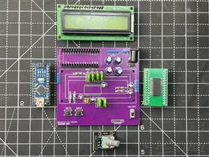
You can get all the files from PCBWAY HUB directly, I soldered all the components by hand. Another approach is to use a stencil or PCB assembly from PCBWAY. The files for all are shared already. PCBWAY is a China based company from where you can get hands on industry standard PCB boards at a really competitive pricing. Sign up now and get hands on first PCB, get the discount coupons for first order.
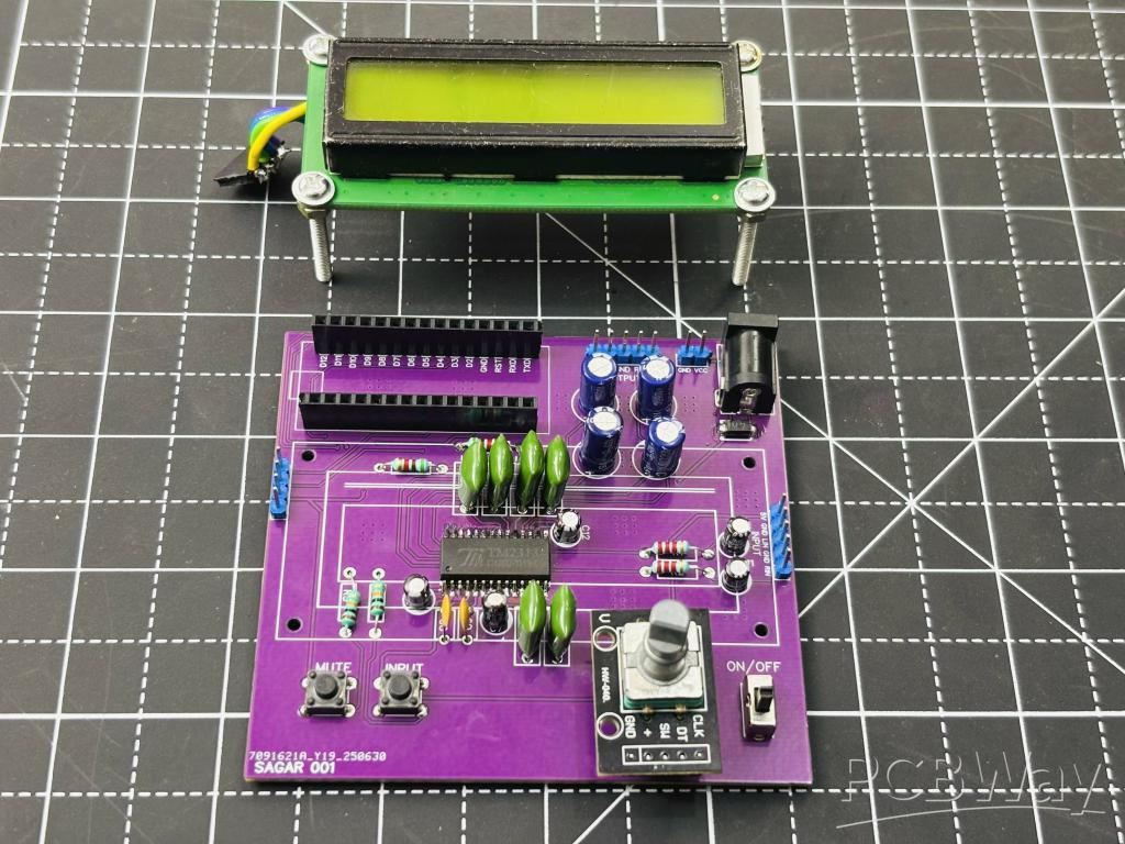
Assembly Instructions:
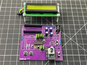
After getting the PCB done plug the programmed Arduino in place. The screen has only 4 wires (I2C), which can be connected to the onboard connector easily. Mount the screen away from the IC, at least 2cm away. I used M2 screws and plugged them into the screen holder and then some hot glue to fix the screen in place. I used a simple 3.0 BT module to give signal and output through the top of the PCB.

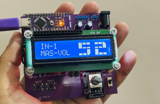
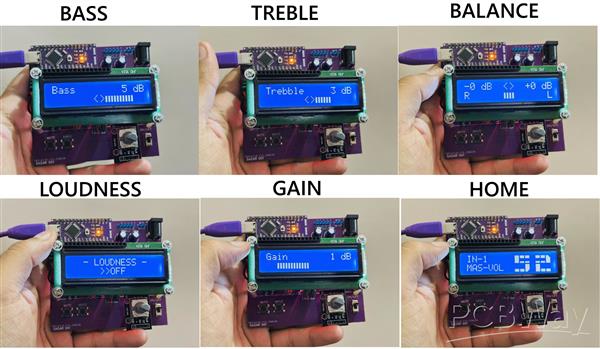
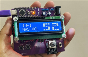
User Interface:
The user interface is smooth and works well with encoder. The menu screen has different options related to volume, treble, bass and gain. All of this can be switched using the encoder button and select the further operation by rotating. See all the screens here:
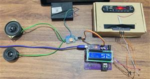
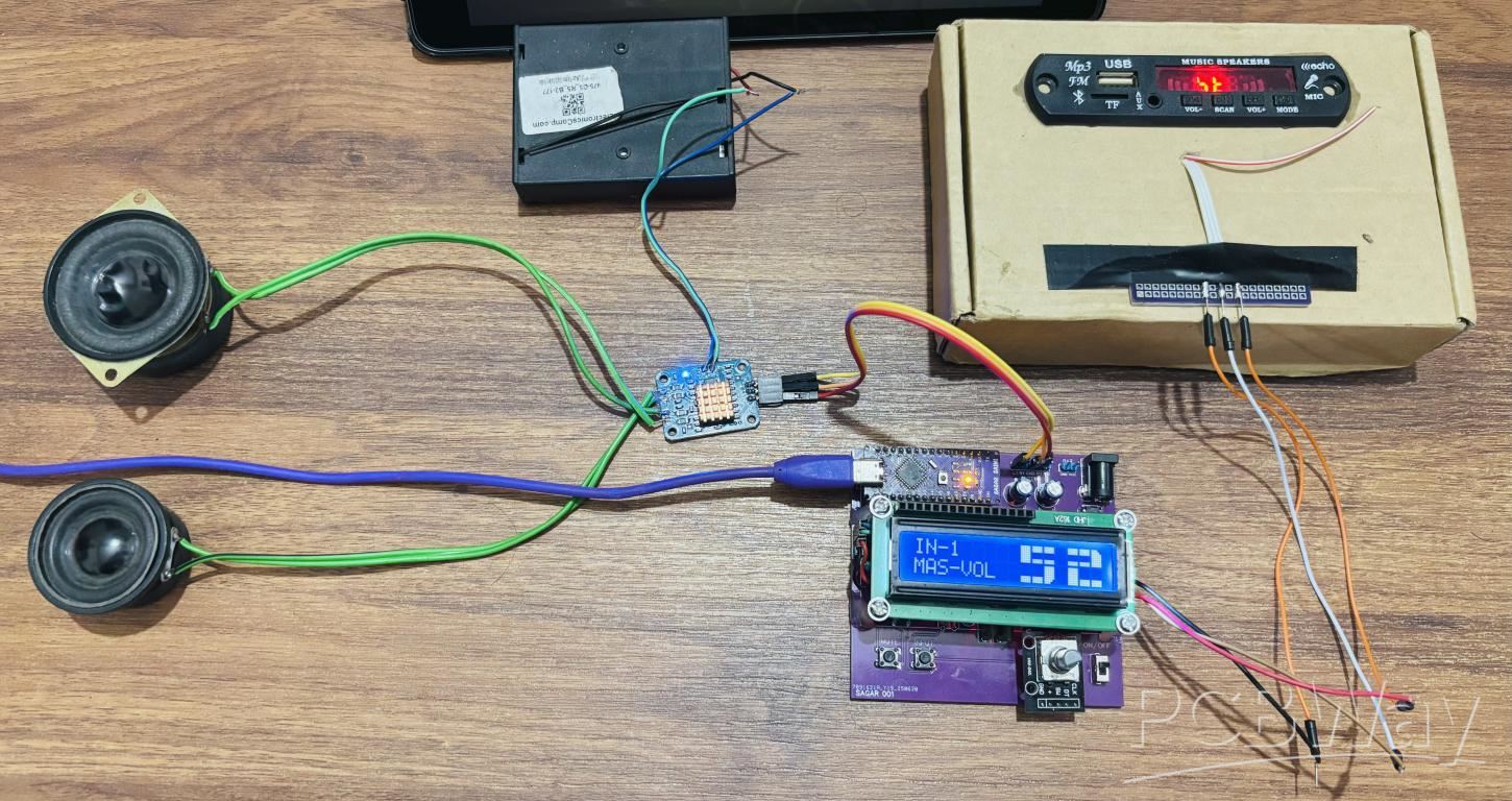
Testing and Working:
I tested the system for all aspects like noise analysis, channels working, gain and signal part. Everything is working very fine, the switching between different screens and selection is quite smooth. Arduino can handle it well. I have a small design tip, use a polyester film capacitor for the external DSP parts. They are not much noise sensitive and work well with high frequencies. The power can be supplied through a 12V jack after plugging everything in place. Now because I am testing this in raw conditions I have a small amplifier and stereo speaker system for analysis. It is obvious that it is only to test the operation of the board. See the attached video for review and consider PCBWAY if you want this PCB.
More Bass Treble and Volume! With PT2313 DSP
*PCBWay community is a sharing platform. We are not responsible for any design issues and parameter issues (board thickness, surface finish, etc.) you choose.


Raspberry Pi 5 7 Inch Touch Screen IPS 1024x600 HD LCD HDMI-compatible Display for RPI 4B 3B+ OPI 5 AIDA64 PC Secondary Screen(Without Speaker)
BUY NOW


- Comments(0)
- Likes(3)
More by Manoj kumar
-
 STK4141 Amplifier is hidden GOLD
Analog audio amplifiers are very powerful enough to make a high noise with stable quality factor. I ...
STK4141 Amplifier is hidden GOLD
Analog audio amplifiers are very powerful enough to make a high noise with stable quality factor. I ...
-
 More Bass Treble and Volume! With PT2313 DSP
When it comes to signal processing through a digital medium then DSPs are the one who comes into pla...
More Bass Treble and Volume! With PT2313 DSP
When it comes to signal processing through a digital medium then DSPs are the one who comes into pla...
-
 Solar Power MPPT Control Li-ion Battery Charger
When talking about standalone single cell battery chargers only one popular name came into my mind t...
Solar Power MPPT Control Li-ion Battery Charger
When talking about standalone single cell battery chargers only one popular name came into my mind t...
-
 AC Power Monitoring Using BL0937 IC
AC power monitoring is an amazing feature nowadays in IoT related applications, such as smart fans, ...
AC Power Monitoring Using BL0937 IC
AC power monitoring is an amazing feature nowadays in IoT related applications, such as smart fans, ...
-
 100W Lab Bench Power Supply From a Fast Charger
Power supplies play a very important role in testing electronic circuits. Power supplies are used to...
100W Lab Bench Power Supply From a Fast Charger
Power supplies play a very important role in testing electronic circuits. Power supplies are used to...
-
 MPPT Solar LIPO Battery Charger
I was just charging my Li-ion battery manually with my IP2312 charger, the high current version I ha...
MPPT Solar LIPO Battery Charger
I was just charging my Li-ion battery manually with my IP2312 charger, the high current version I ha...
-
 DIY Portable Power Supply
Whenever I am travelling from one place to another, I used to keep my electronics with me. And somet...
DIY Portable Power Supply
Whenever I am travelling from one place to another, I used to keep my electronics with me. And somet...
-
 I made a Nano USB HUB
I want to use the USB hub internally in my laptop but the available ones are very bulky and do not s...
I made a Nano USB HUB
I want to use the USB hub internally in my laptop but the available ones are very bulky and do not s...
-
 I made an ARDUINO NANO Clone Board
I made a series of Arduino Atmega328 boards and every new version has something new. We always learn...
I made an ARDUINO NANO Clone Board
I made a series of Arduino Atmega328 boards and every new version has something new. We always learn...
-
 Arduino Got Pro Max upgrade!!
I am aware of sensors, modules and integrated circuit used with microcontrollers like Arduino. And I...
Arduino Got Pro Max upgrade!!
I am aware of sensors, modules and integrated circuit used with microcontrollers like Arduino. And I...
-
 Minimal Component tester using Arduino
You might know component tester and its different versions made by many hobbyists. Today I have made...
Minimal Component tester using Arduino
You might know component tester and its different versions made by many hobbyists. Today I have made...
-
 Making a Digital Light Measuring Meter
While working on a home automation project on light, the light intensity unit- lux (lumens per squar...
Making a Digital Light Measuring Meter
While working on a home automation project on light, the light intensity unit- lux (lumens per squar...
-
 IR Jammer circuit using NE555 timer
I am working on IR protocol in university research Centre and then an idea of IR jammer comes into m...
IR Jammer circuit using NE555 timer
I am working on IR protocol in university research Centre and then an idea of IR jammer comes into m...
-
 Variable Current/Voltage DC power supply
To power up electronics circuits or while testing different voltage-ampere/power ranges are required...
Variable Current/Voltage DC power supply
To power up electronics circuits or while testing different voltage-ampere/power ranges are required...
-
 PCB soldering reflow hot Plate! A good Idea?
let’s talk about soldering in a new and easy method. Because I am working with SMT components and st...
PCB soldering reflow hot Plate! A good Idea?
let’s talk about soldering in a new and easy method. Because I am working with SMT components and st...
-
 Non-contact Infrared temperature sensor using Arduino
Hello guys, I want to make my own most accurate temperature meter. When coming to the high temperatu...
Non-contact Infrared temperature sensor using Arduino
Hello guys, I want to make my own most accurate temperature meter. When coming to the high temperatu...
-
 Arduino serial Programmer CH340N
There are lot of programmer boards that are compatible with Arduino. But the cheapest and smaller on...
Arduino serial Programmer CH340N
There are lot of programmer boards that are compatible with Arduino. But the cheapest and smaller on...
-
 My own Arduino Nano Microcontroller board
Here is my new Arduino Nano board, This looks better with C-type and one step above compatible drive...
My own Arduino Nano Microcontroller board
Here is my new Arduino Nano board, This looks better with C-type and one step above compatible drive...
-
Programmable Mist Maker - XIAO / QT PY Extension
247 0 0 -
RadioHAT - Raspberry Pi radio development platform
269 0 1 -
-
-
-
-
ARPS-2 – Arduino-Compatible Robot Project Shield for Arduino UNO
2827 0 6 -
A Compact Charging Breakout Board For Waveshare ESP32-C3
3332 3 8 -
AI-driven LoRa & LLM-enabled Kiosk & Food Delivery System
3629 2 2


