


|
Soldering iron |
|

|
Soldering Iron Wire Welding Lead Roll |
Variable Current/Voltage DC power supply
To power up electronics circuits or while testing different voltage-ampere/power ranges are required. We can not deliver that power from a single battery. Either we have to put a buck converter or linear voltage regulator. But most of the low-price buck converter has a current limit maximum of 2amperes.
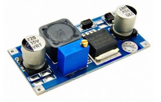
When it comes to low resistance load the power draw increases and it will shut down the buck converter automatically. What if we have to power the load with high amperes at a desired voltage.
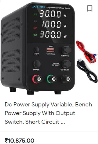
The bench power supplies may be the best option in this case. Most of the bench supplies have constant current/ voltage setup regulator, a big screen and a high power SMPS. But due to high price and availability somehow it is not possible to buy at all.
Bench power supplies:
Ac power is converted into DC through SMPS and then it is supplied to Controller circuit. Which is used to make desirable changes in the supply voltage and current. A sensitive voltmeter is connected in parallel with output for voltage measurements and ammeter in series with the one output terminal to measure current. Which is the main display of the bench power supplies. Some of them come with power measurements also.
Power = Voltage*Current
So, a small micro-controller is used to calculate the values, compute the values and to display the values.
Our setup:
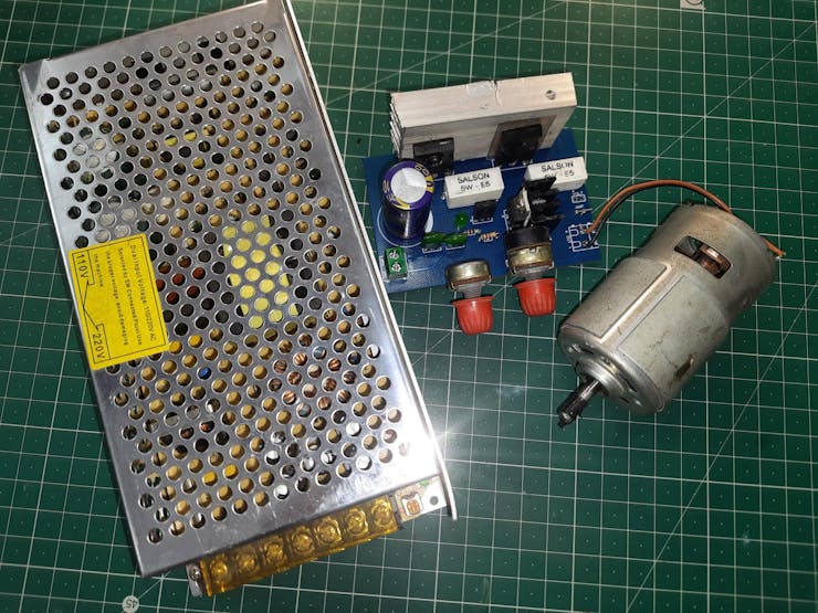
Instead of making an SMPS we can order one in cheap and then connect controller circuitry to make an own bench power supply with constant current and voltage features. We can use high power transistor for switching with linear voltage regulator. Which can give a maximum output of constant 10amperes an heavy load. Now coming to the display part, either we can use 2 multimeters, one in voltage measurement mode other in current mode. Or buy a cheap voltage-current measuring display.
Components required:
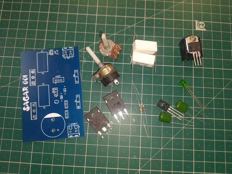
1) TIP3055 Power Transistor
2) 0.5ohms resistor 5watts
3) 10k, 4.7k potentiometer
4) LM317 Voltage regulator
5) 1k, 220R Resistors
6) BD139 transistor
6) 100nf capacitor
7) 3500uf electrolytic capacitor (50v)
8)) Custom PCB(PCBWAY)
Circuit diagram:
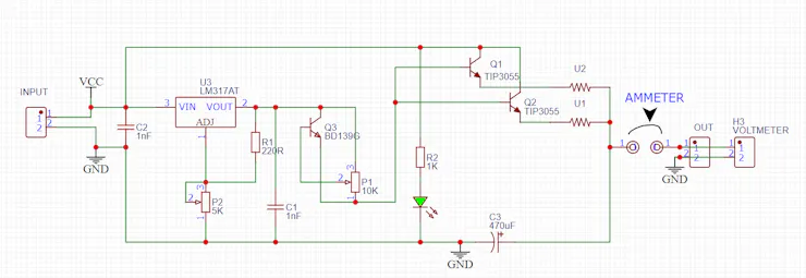
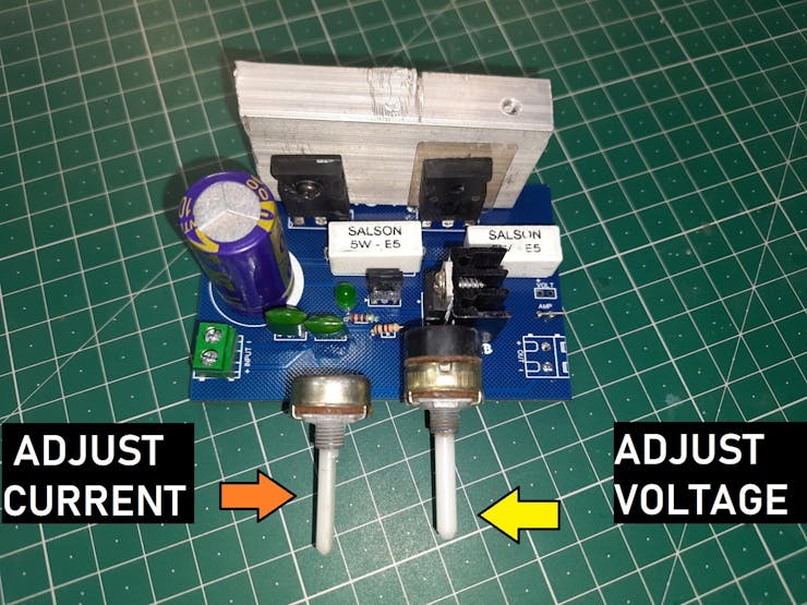
Connect all the circuitry according to the circuit diagram. 4.7k potentiometer is used for current adjustment and 10k for voltage setup. I always recommend to use this circuit only with SMPS power supply or high filtered linear power supply unit. Excessive ripple may cause problems and can change the adjusted settings with time.
PCB Designs:
According to the circuit diagram I developed a PCB layout and if you want to use the same you can Download Gerber files from here.
I used 1.6mm, blue colored and Hasl PCBs. These PCBs are manufactured by PCBWAY and the quality they are offering at this price range is absolutely very great. Sign-up to PCBWAY from here and get free PCB coupons. If you want to know more about PCBWAY and services then follow this article here" Why I choose PCBWAY for my projects".
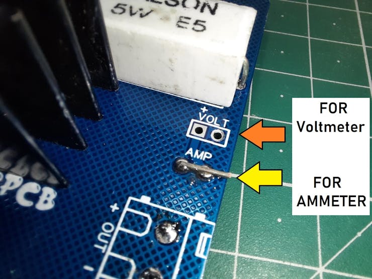
In the PCB designs I also added a voltage and current meter adding feature. As you know voltmeter can be connected the parallel with the output to display the output voltage value. In the same way current meter can be connected in series and if you don't want to use current meter for now then just short these two terminals with a piece of wire.
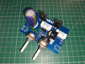
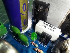
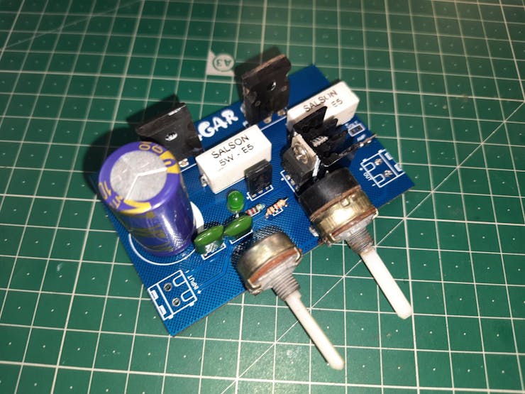
Assembly:
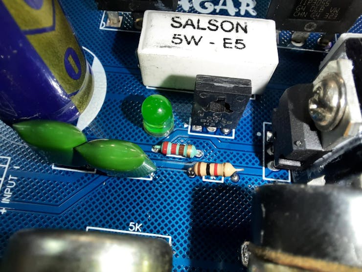
I assembled the small components Resistors/diodes first and then capacitors and other high wattage big resistors. After soldering all of these components I placed the main power transistors and soldered them on place.
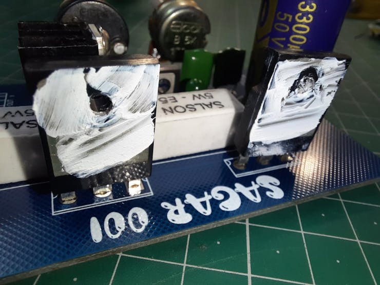
A constant current of 5-10 amperes is too much and cause heat on the transistors. So we need a big heatsink with proper compound paste and mica sheets for insulations.
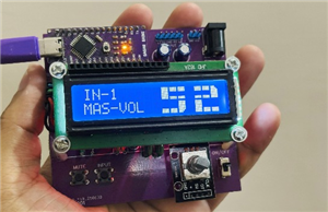
Working:
It can adjust the current from 0-10 amperes on a voltage range of 0-30 volts. If you want to test the action then a high power load may show you the proper results.
But here for the test we used this DC775 motor. And our circuit is handling this very accurately.
How to order PCB from PCBWAY:
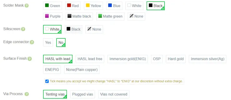
First, Go to PCBWAY and sign-up using this link. Click on instant quote and choose the designed PCB dimensions, If wrong then corrected by the team of engineers.
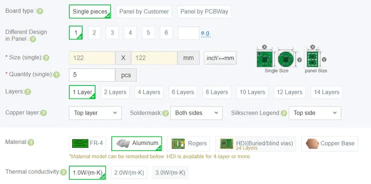
Select the quantity, thickness, color, material and Finishing type.
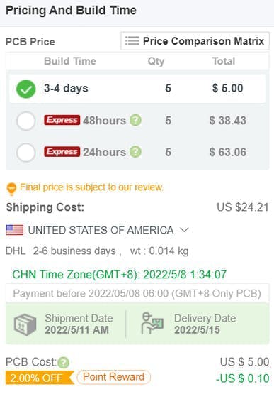
Calculate the PCB cost and then save it to cart.
Upload the Gerber file, now engineers will inspect the PCB dimensions, tracks and type and give you the final quote (This will take 5 to 10 minutes).
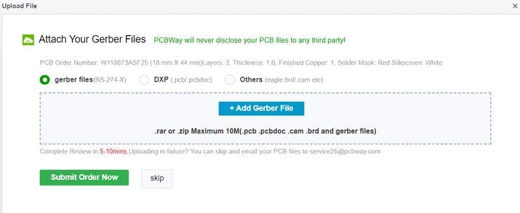
Checkout and get your PCB just in 7 days at home.

Variable Current/Voltage DC power supply
*PCBWay community is a sharing platform. We are not responsible for any design issues and parameter issues (board thickness, surface finish, etc.) you choose.


Raspberry Pi 5 7 Inch Touch Screen IPS 1024x600 HD LCD HDMI-compatible Display for RPI 4B 3B+ OPI 5 AIDA64 PC Secondary Screen(Without Speaker)
BUY NOW


- Comments(1)
- Likes(1)
More by Manoj kumar
-
 STK4141 Amplifier is hidden GOLD
Analog audio amplifiers are very powerful enough to make a high noise with stable quality factor. I ...
STK4141 Amplifier is hidden GOLD
Analog audio amplifiers are very powerful enough to make a high noise with stable quality factor. I ...
-
 More Bass Treble and Volume! With PT2313 DSP
When it comes to signal processing through a digital medium then DSPs are the one who comes into pla...
More Bass Treble and Volume! With PT2313 DSP
When it comes to signal processing through a digital medium then DSPs are the one who comes into pla...
-
 Solar Power MPPT Control Li-ion Battery Charger
When talking about standalone single cell battery chargers only one popular name came into my mind t...
Solar Power MPPT Control Li-ion Battery Charger
When talking about standalone single cell battery chargers only one popular name came into my mind t...
-
 AC Power Monitoring Using BL0937 IC
AC power monitoring is an amazing feature nowadays in IoT related applications, such as smart fans, ...
AC Power Monitoring Using BL0937 IC
AC power monitoring is an amazing feature nowadays in IoT related applications, such as smart fans, ...
-
 100W Lab Bench Power Supply From a Fast Charger
Power supplies play a very important role in testing electronic circuits. Power supplies are used to...
100W Lab Bench Power Supply From a Fast Charger
Power supplies play a very important role in testing electronic circuits. Power supplies are used to...
-
 MPPT Solar LIPO Battery Charger
I was just charging my Li-ion battery manually with my IP2312 charger, the high current version I ha...
MPPT Solar LIPO Battery Charger
I was just charging my Li-ion battery manually with my IP2312 charger, the high current version I ha...
-
 DIY Portable Power Supply
Whenever I am travelling from one place to another, I used to keep my electronics with me. And somet...
DIY Portable Power Supply
Whenever I am travelling from one place to another, I used to keep my electronics with me. And somet...
-
 I made a Nano USB HUB
I want to use the USB hub internally in my laptop but the available ones are very bulky and do not s...
I made a Nano USB HUB
I want to use the USB hub internally in my laptop but the available ones are very bulky and do not s...
-
 I made an ARDUINO NANO Clone Board
I made a series of Arduino Atmega328 boards and every new version has something new. We always learn...
I made an ARDUINO NANO Clone Board
I made a series of Arduino Atmega328 boards and every new version has something new. We always learn...
-
 Arduino Got Pro Max upgrade!!
I am aware of sensors, modules and integrated circuit used with microcontrollers like Arduino. And I...
Arduino Got Pro Max upgrade!!
I am aware of sensors, modules and integrated circuit used with microcontrollers like Arduino. And I...
-
 Minimal Component tester using Arduino
You might know component tester and its different versions made by many hobbyists. Today I have made...
Minimal Component tester using Arduino
You might know component tester and its different versions made by many hobbyists. Today I have made...
-
 Making a Digital Light Measuring Meter
While working on a home automation project on light, the light intensity unit- lux (lumens per squar...
Making a Digital Light Measuring Meter
While working on a home automation project on light, the light intensity unit- lux (lumens per squar...
-
 IR Jammer circuit using NE555 timer
I am working on IR protocol in university research Centre and then an idea of IR jammer comes into m...
IR Jammer circuit using NE555 timer
I am working on IR protocol in university research Centre and then an idea of IR jammer comes into m...
-
 Variable Current/Voltage DC power supply
To power up electronics circuits or while testing different voltage-ampere/power ranges are required...
Variable Current/Voltage DC power supply
To power up electronics circuits or while testing different voltage-ampere/power ranges are required...
-
 PCB soldering reflow hot Plate! A good Idea?
let’s talk about soldering in a new and easy method. Because I am working with SMT components and st...
PCB soldering reflow hot Plate! A good Idea?
let’s talk about soldering in a new and easy method. Because I am working with SMT components and st...
-
 Non-contact Infrared temperature sensor using Arduino
Hello guys, I want to make my own most accurate temperature meter. When coming to the high temperatu...
Non-contact Infrared temperature sensor using Arduino
Hello guys, I want to make my own most accurate temperature meter. When coming to the high temperatu...
-
 Arduino serial Programmer CH340N
There are lot of programmer boards that are compatible with Arduino. But the cheapest and smaller on...
Arduino serial Programmer CH340N
There are lot of programmer boards that are compatible with Arduino. But the cheapest and smaller on...
-
 My own Arduino Nano Microcontroller board
Here is my new Arduino Nano board, This looks better with C-type and one step above compatible drive...
My own Arduino Nano Microcontroller board
Here is my new Arduino Nano board, This looks better with C-type and one step above compatible drive...
-
-
ARPS-2 – Arduino-Compatible Robot Project Shield for Arduino UNO
2241 0 5 -
A Compact Charging Breakout Board For Waveshare ESP32-C3
2733 3 7 -
AI-driven LoRa & LLM-enabled Kiosk & Food Delivery System
2927 2 0 -
-
-
-
ESP32-C3 BLE Keyboard - Battery Powered with USB-C Charging
2964 0 2 -


