


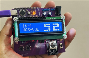
Minimal Component tester using Arduino
You might know component tester and its different versions made by many hobbyists. Today I have made a minimal version of this component tester, using some SMD components along with Through hole. I used Arduino Nano microcontroller as the brain of project. And after using a suitable resistor divider network you can get very accurate value of most of the components.
I want to keep it simple, so I choose 16x2 LCD screen. It is able to display all the graphics through symbols, numbers and alphabets. I am here for only sharing the experience in building nothing about the code. Code for this project can be downloaded from here. If you want to know more about the tester working and principle then refer to this 100-page manual. Which has all info about modes, screen types, Microcontrollers and software.
I made these PCB using PCBWAY prototyping service, starting from $5 for 5 PCB. I always use PCBway prototyping service for my projects to give them a better look and to reduce overall efforts. Sign-up to PCBWAY using this link to get free new user coupons.
Why minimal version:
First, to reduce the overall cost of the system. And secondly many of the Ardu-tester Arduino code give error. But through this minimal system you can test different codes and then implement one in your next project. I am making this for test purpose that’s why I don’t use any battery. Real time on bench testing gives the real behavior of the project.
Components required:
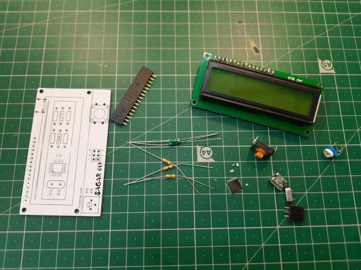
1) Arduino Nano
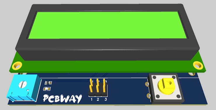
2) 16x2 LCD
3) 100nf capacitors
4) 1k resistor
5) 16Mhz crystal oscillator
6) 22pf capacitors
7) Type C charging jack
Circuit diagram:
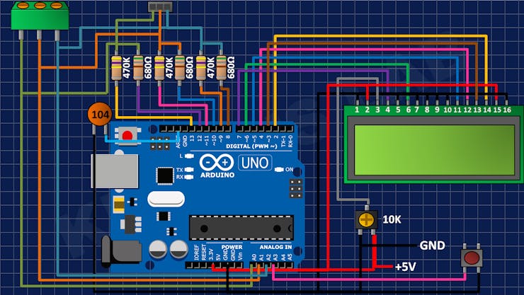
This version is limited to directly use with USB; this version doesn’t offer any protection against voltage. So, try to use a power bank or fixed value power module. A tactile button is connected to A3 pin of the Arduino which is used to reset the system and test.
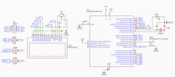
Arduino SMD microcontroller with 16Mhz crystal and 22pf capacitor for impedance matching. 470K and 680 Ohms resistor divider network is given to the ADC of Arduino. These values can be calibrated inside the code also. I always to prefer to get a microcontroller chip directly from the top of Arduino Nano after burning sketch into it.
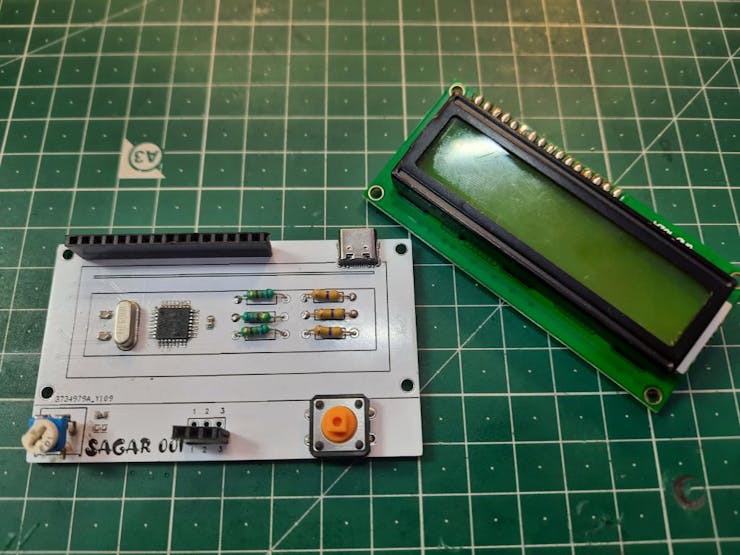
PCB designs:
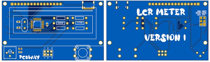
I made this minimal design using the above given modified schematics. You can download all the files and code from here. Programming headers are added on the back layer to change/ update the firmware.
I am using FR4 material, Hasl finish, white solder mask and 1.6mm thickness. A very thanks to PCBWAY for sponsoring this project. PCBway is one of leading PCB manufacturing company in China. Deals in PCB manufacturing, SMT assembly, PCBA, stencil, 3D- printing and CNC. Try out the more services from here now, and get free PCB coupons on first Sign-up using this link. Get your 5 pcs of PCB boards in just $5.
Code:
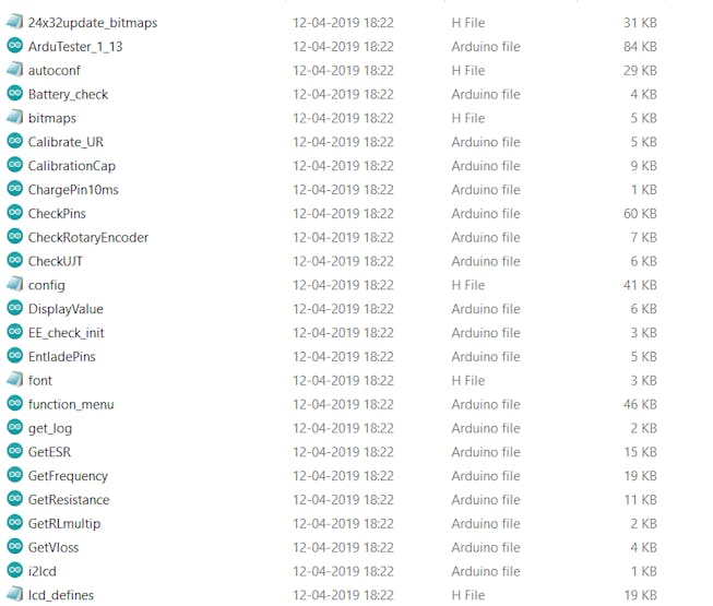
Full code can be downloaded from here, try to install the latest libraries for the LCD. You can comment here, if found any problem in uploading the code. The code calls more than 10 files, so don’t get confuse with that only keep focus on Ardu-tester_1_13 and upload it using simple steps.
Working:
This component tester can test all of the passive components and most of Active components. Like- Resistor, capacitor, inductor, Transistor, UJT, Mosfet, IGBT, Diode and LEDs. Here I made some tests using my version:
![]()
This version not only tells the value of component but also give a small usable datasheet like for a transistor its pins, configuration and gain can be obtained.
Testing Mosfet:
Testing Capacitor:
Testing Inductor:
You may refer to a YouTube channel named as eevblog who actually explained the working of resistor divider network and how wisely this meter is designed. Using a very less external circuit this meter covers almost every electronic component. The software is very optimized and thanks to maker to give us such an extraordinary device.
Ordering PCB from PCBWAY:
PCBway has introduced a new plugin for the KICAD, now you can directly add your designed Gerber into PCBWAY cart. Here are few steps you may follow to add this plugin into your KICAD software.
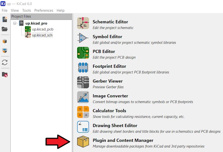
Open the KICAD designer and click on plugin and content manager.
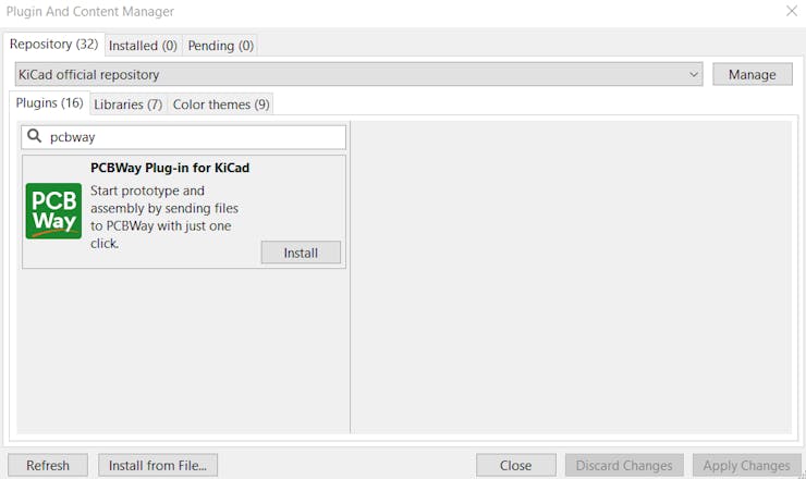
Write PCBWAY in repository then download and install the latest version.
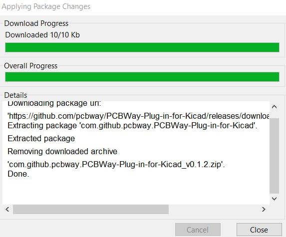
To update the plugin in real time in editor, go to the tools menu and then to the external plugins, refresh the system, it will update the settings and then show a PCBWAY logo on the toolbar. Which redirects to PCBWAY webpage and upload the Gerbers directly.
Next version:
We will reduce the overall connection by using a 12c module with 16x2 LCD. And a small battery with proper charging and protection features. And a new version of software to fix all the existing bugs and adds new features also with hardware.
Minimal Component tester using Arduino
Project images are for reference only. Actual production is based on the manufacturing files on the project page.
Please review the designer's notes (e.g., PCB thickness) and select the appropriate options.
PCBWay is not responsible
for issues caused by unsuitable parameter selections.
For more important ordering information, please refer to
Read More


Raspberry Pi 5 7 Inch Touch Screen IPS 1024x600 HD LCD HDMI-compatible Display for RPI 4B 3B+ OPI 5 AIDA64 PC Secondary Screen(Without Speaker)
BUY NOW


- Comments(0)
- Likes(4)
 More by Manoj kumar
-
 STK4141 Amplifier is hidden GOLD
Analog audio amplifiers are very powerful enough to make a high noise with stable quality factor. I ...
STK4141 Amplifier is hidden GOLD
Analog audio amplifiers are very powerful enough to make a high noise with stable quality factor. I ...
-
 More Bass Treble and Volume! With PT2313 DSP
When it comes to signal processing through a digital medium then DSPs are the one who comes into pla...
More Bass Treble and Volume! With PT2313 DSP
When it comes to signal processing through a digital medium then DSPs are the one who comes into pla...
-
 Solar Power MPPT Control Li-ion Battery Charger
When talking about standalone single cell battery chargers only one popular name came into my mind t...
Solar Power MPPT Control Li-ion Battery Charger
When talking about standalone single cell battery chargers only one popular name came into my mind t...
-
 AC Power Monitoring Using BL0937 IC
AC power monitoring is an amazing feature nowadays in IoT related applications, such as smart fans, ...
AC Power Monitoring Using BL0937 IC
AC power monitoring is an amazing feature nowadays in IoT related applications, such as smart fans, ...
-
 100W Lab Bench Power Supply From a Fast Charger
Power supplies play a very important role in testing electronic circuits. Power supplies are used to...
100W Lab Bench Power Supply From a Fast Charger
Power supplies play a very important role in testing electronic circuits. Power supplies are used to...
-
 MPPT Solar LIPO Battery Charger
I was just charging my Li-ion battery manually with my IP2312 charger, the high current version I ha...
MPPT Solar LIPO Battery Charger
I was just charging my Li-ion battery manually with my IP2312 charger, the high current version I ha...
-
 DIY Portable Power Supply
Whenever I am travelling from one place to another, I used to keep my electronics with me. And somet...
DIY Portable Power Supply
Whenever I am travelling from one place to another, I used to keep my electronics with me. And somet...
-
 I made a Nano USB HUB
I want to use the USB hub internally in my laptop but the available ones are very bulky and do not s...
I made a Nano USB HUB
I want to use the USB hub internally in my laptop but the available ones are very bulky and do not s...
-
 I made an ARDUINO NANO Clone Board
I made a series of Arduino Atmega328 boards and every new version has something new. We always learn...
I made an ARDUINO NANO Clone Board
I made a series of Arduino Atmega328 boards and every new version has something new. We always learn...
-
 Arduino Got Pro Max upgrade!!
I am aware of sensors, modules and integrated circuit used with microcontrollers like Arduino. And I...
Arduino Got Pro Max upgrade!!
I am aware of sensors, modules and integrated circuit used with microcontrollers like Arduino. And I...
-
 Minimal Component tester using Arduino
You might know component tester and its different versions made by many hobbyists. Today I have made...
Minimal Component tester using Arduino
You might know component tester and its different versions made by many hobbyists. Today I have made...
-
 Making a Digital Light Measuring Meter
While working on a home automation project on light, the light intensity unit- lux (lumens per squar...
Making a Digital Light Measuring Meter
While working on a home automation project on light, the light intensity unit- lux (lumens per squar...
-
 IR Jammer circuit using NE555 timer
I am working on IR protocol in university research Centre and then an idea of IR jammer comes into m...
IR Jammer circuit using NE555 timer
I am working on IR protocol in university research Centre and then an idea of IR jammer comes into m...
-
 Variable Current/Voltage DC power supply
To power up electronics circuits or while testing different voltage-ampere/power ranges are required...
Variable Current/Voltage DC power supply
To power up electronics circuits or while testing different voltage-ampere/power ranges are required...
-
 PCB soldering reflow hot Plate! A good Idea?
let’s talk about soldering in a new and easy method. Because I am working with SMT components and st...
PCB soldering reflow hot Plate! A good Idea?
let’s talk about soldering in a new and easy method. Because I am working with SMT components and st...
-
 Non-contact Infrared temperature sensor using Arduino
Hello guys, I want to make my own most accurate temperature meter. When coming to the high temperatu...
Non-contact Infrared temperature sensor using Arduino
Hello guys, I want to make my own most accurate temperature meter. When coming to the high temperatu...
-
 Arduino serial Programmer CH340N
There are lot of programmer boards that are compatible with Arduino. But the cheapest and smaller on...
Arduino serial Programmer CH340N
There are lot of programmer boards that are compatible with Arduino. But the cheapest and smaller on...
-
 My own Arduino Nano Microcontroller board
Here is my new Arduino Nano board, This looks better with C-type and one step above compatible drive...
My own Arduino Nano Microcontroller board
Here is my new Arduino Nano board, This looks better with C-type and one step above compatible drive...
-
Programmable Mist Maker - XIAO / QT PY Extension
1061 2 1 -
RadioHAT - Raspberry Pi radio development platform
861 0 2 -
-
-
-
-
ARPS-2 – Arduino-Compatible Robot Project Shield for Arduino UNO
3322 0 6 -
A Compact Charging Breakout Board For Waveshare ESP32-C3
3930 3 8 -
AI-driven LoRa & LLM-enabled Kiosk & Food Delivery System
4316 2 2


