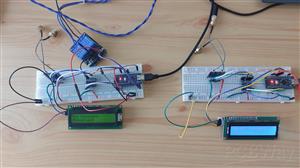
Long-Range Appliance Control Using Arduino and RYLR999 LoRa
Controlling an appliance wirelessly is straightforward when Wi-Fi is available, but things become more interesting when the device is located outside the coverage of your local network.
In this project, I built a long-range appliance control system using two Arduino Nano boards and Reyax RYLR999 modules. The system uses Bluetooth Low Energy (BLE) for communication with a smartphone and LoRa for the long-distance wireless link.
The smartphone sends a simple command to the controller node through BLE. The controller Arduino processes the command and sends it through the LoRa interface of the RYLR999. A second RYLR999 at the remote end receives the message, and another Arduino Nano controls the required appliance through a relay.
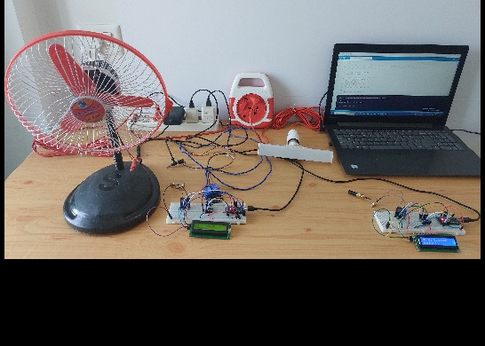
For the prototype, I used a 240V AC bulb and a 12V DC fan as the loads.
The complete project was originally documented on Play with Circuit, and this version focuses more on the hardware architecture, interfacing, and practical implementation.
Project Overview
The system has two main sections:
Controller Node
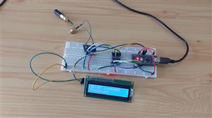
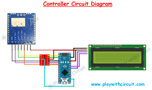
The controller is connected to the smartphone. It contains an Arduino Nano, RYLR999 module, voltage level shifter, and 16×2 I2C LCD.
Target Node
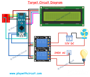
The target is installed near the appliances. It contains another Arduino Nano, RYLR999 module, voltage level shifter, LCD, and two-channel relay module.
The communication sequence is:
Smartphone → BLE → Controller Arduino → LoRa → Target Arduino → Relay → Appliance
The target node also sends a response back to the controller after executing the command.
This makes the system bidirectional rather than simply sending a one-way switching command.
Main Hardware
The prototype uses the following hardware:
Arduino Nano ×2
Reyax RYLR999 ×2
5V bidirectional voltage level shifter ×2
16×2 I2C LCD ×2
2-channel relay module
12V DC fan
240V AC bulb
12V power supply
Jumper wires
Smartphone with LightBlue BLE application
The same architecture could later be redesigned around a custom PCB instead of using jumper wires and separate modules.
Why RYLR999?
The RYLR999 is particularly useful for this project because it combines BLE and LoRa communication.
The BLE interface provides a convenient way to connect a smartphone to the controller without building a dedicated mobile application during the prototype stage.
LoRa is then used for the actual long-range communication between the controller and target nodes.
This separation keeps the system simple:
BLE = local user interface
LoRa = long-range wireless link
RYLR999 and Arduino Interface
The RYLR999 provides separate UART connections for its BLE and LoRa interfaces.
The important pins used in this project are:
VDD
GND
RST
TXD_BLE
RXD_BLE
TXD_LoRa
RXD_LoRa
The Arduino Nano operates using 5V logic, while the RYLR999 uses 3.3V logic for its communication interface. Therefore, the UART connections are routed through a bidirectional voltage level shifter.
This is an important part of the hardware design. The level shifter allows the 5V Arduino signals and 3.3V module signals to interface safely.
Controller Node Wiring
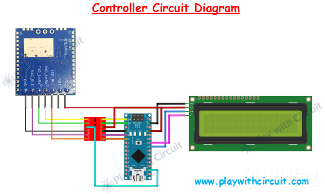
The controller Arduino communicates with the LoRa portion of the RYLR999 through its hardware serial interface.
The Arduino Nano's RX pin (D0) receives the LoRa data from the module's TXD_LoRa pin through the voltage level shifter.
The Arduino's TX pin (D1) sends data toward RXD_LoRa, again through the level shifter.
BLE communication uses SoftwareSerial because the Nano has only one hardware UART. Digital pin D2 is used for BLE transmission and D3 for BLE reception.
The connections are therefore:
D0 → level shifter → TXD_LoRa
D1 → level shifter → RXD_LoRa
D2 → level shifter → RXD_BLE
D3 → level shifter → TXD_BLE
The RYLR999 is powered from the appropriate supply and shares a common ground with the Arduino.
Voltage Level Shifter Connections
The level shifter has separate high-voltage and low-voltage sides.
The HV side is connected to the Arduino's 5V logic supply, while the LV side is connected to the 3.3V side used by the RYLR999.
The Arduino's 5V pin is connected to the HV supply pin of the level shifter, and the Arduino's 3.3V pin is connected to the LV supply pin.
This arrangement allows the UART signals to be translated between the two voltage domains.
It is important not to treat the level shifter as optional simply because the UART signals may appear to work during a quick test. The purpose is to keep the logic levels within the appropriate range for the connected hardware.
Controller LCD
The 16×2 LCD uses an I2C interface.
Connect:
LCD VCC → Arduino 5V
LCD GND → Arduino GND
LCD SDA → Arduino A4
LCD SCL → Arduino A5
The LCD module used in the prototype uses the I2C address 0x27. The address jumpers on the LCD backpack should remain open for this configuration. The display is useful during development because it provides a quick indication of what the controller is receiving and transmitting.
Target Node Wiring
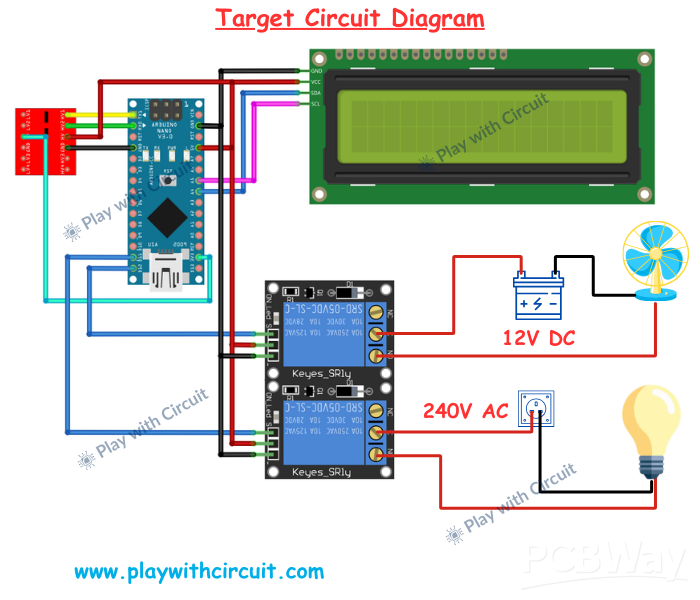
The target node uses the same basic LoRa UART connection as the controller.
The second RYLR999 receives the long-range data and passes it to the Arduino Nano.
Unlike the controller, the target does not need the BLE interface because it is only concerned with receiving LoRa commands and operating the connected loads.
The LoRa UART lines again pass through the bidirectional voltage level shifter.
The target Arduino then uses two digital outputs for relay control:
D11 → Relay Channel 1 → Bulb
D12 → Relay Channel 2 → Fan
The target LCD is connected to A4 and A5 in the same way as the controller LCD.
Relay Interface
The relay module provides the switching interface between the Arduino and the appliances.
Relay channel 1 is controlled by Arduino D11 and is used for the bulb.
Relay channel 2 is controlled by D12 and is used for the fan.
The relay module's VCC is connected to the Arduino's 5V supply and its GND is connected to common ground.
For the 12V DC fan, the relay is placed in series with the 12V supply line. Activating the relay closes the circuit and powers the fan.
For the 240V AC bulb, the relay switches the live conductor of the AC supply. The live line is connected to the relay's common terminal, while the normally-open contact connects to the bulb.
The AC portion must be treated separately from the low-voltage electronics.
Disconnect mains power before making any AC connections, and use appropriately rated components, wiring, enclosure, and protection. If you are not qualified to work with mains voltage, have the AC portion wired by a qualified person.
Communication Process
The commands used by the smartphone application are deliberately simple:
*L1# — Bulb ON
*L0# — Bulb OFF
*F1# — Fan ON
*F0# — Fan OFF
When a command reaches the controller through BLE, the Arduino identifies the requested operation and forwards the corresponding data through the LoRa interface.
The target Arduino receives the LoRa message and determines which relay needs to be activated.
For example, when the user sends:
*L1#
the controller interprets it as a bulb ON command. The LoRa module sends the command to the remote node, where Arduino activates D11 and switches relay channel 1.
The target then returns a confirmation such as:
DONE
The LCDs can be used to monitor this process.
Why Use Two Separate Nodes?
Separating the controller and target sections makes the design easier to understand and expand.
The controller can remain with the user while the target node can be installed wherever the appliance is located.
The target hardware can also be modified independently. For example, instead of controlling a fan and bulb, the same relay interface could eventually operate a pump, motor contactor, lighting circuit, or other suitable load.
Multiple target nodes could also be considered for a larger system.
Testing
Possible Improvements
The prototype can be extended in several directions.
A custom smartphone application could replace the LightBlue application and provide dedicated appliance controls and status indicators.
Sensors could be added to the target node so that the system not only controls appliances but also reports environmental or machine data back to the controller.
For remote agricultural applications, for example, the target could monitor soil moisture and operate an irrigation pump based on commands or sensor readings.
A battery and solar charging system could also be added for locations without a convenient power source.
Conclusion
This project demonstrates a practical way of combining BLE and LoRa in the same wireless control system.
BLE provides the short-range connection between the smartphone and controller, while LoRa handles the long-distance link to the remote appliance node.
The prototype uses two Arduino Nano boards, two RYLR999 modules, voltage level shifters, LCD displays, and a relay module to control both DC and AC loads.
More importantly, the design provides a good starting point for moving from a prototype built with development boards to a dedicated PCB with integrated power, communication, and relay-control circuitry.
For the complete project documentation, source code, and additional implementation details, I have documented the project on Play with Circuit:
Long-Range Appliance Control from Smartphone Using Arduino
https://playwithcircuit.com/long-range-appliance-control-from-smartphone-using-arduino/
Long-Range Appliance Control Using Arduino and RYLR999 LoRa









Raspberry Pi 5 7 Inch Touch Screen IPS 1024x600 HD LCD HDMI-compatible Display for RPI 4B 3B+ OPI 5 AIDA64 PC Secondary Screen(Without Speaker)
BUY NOW

- Comments(0)
- Likes(0)
More by Rachana Jain
-
 Building a UWB Distance Monitoring and Alert System with Arduino UNO
Measuring the distance between two devices is a useful capability in robotics, wireless sensing, and...
Building a UWB Distance Monitoring and Alert System with Arduino UNO
Measuring the distance between two devices is a useful capability in robotics, wireless sensing, and...
-
 HC-SR501 PIR Motion Sensor: Working, Pinout, and Arduino Interface
Motion detection is a common requirement in embedded and electronics systems. Applications such as a...
HC-SR501 PIR Motion Sensor: Working, Pinout, and Arduino Interface
Motion detection is a common requirement in embedded and electronics systems. Applications such as a...
-
 Interfacing OLED Display with Arduino
OLED displays are a useful upgrade over traditional character LCDs when an Arduino project needs a c...
Interfacing OLED Display with Arduino
OLED displays are a useful upgrade over traditional character LCDs when an Arduino project needs a c...
-
 Long-Range Appliance Control Using Arduino and RYLR999 LoRa
Controlling an appliance wirelessly is straightforward when Wi-Fi is available, but things become mo...
Long-Range Appliance Control Using Arduino and RYLR999 LoRa
Controlling an appliance wirelessly is straightforward when Wi-Fi is available, but things become mo...
-
 GPS Tracker using Heltec WiFi LoRa 32 V4 and REYAX RYS352A GNSS Module
This browser-based GPS tracker combines the Heltec WiFi LoRa 32 V4 development board with the REYAX ...
GPS Tracker using Heltec WiFi LoRa 32 V4 and REYAX RYS352A GNSS Module
This browser-based GPS tracker combines the Heltec WiFi LoRa 32 V4 development board with the REYAX ...
-
 Arduino Stepper Motor Control Using 28BYJ-48 and ULN2003 Driver
This project demonstrates how to control the popular 28BYJ-48 5V stepper motor using an Arduino Uno ...
Arduino Stepper Motor Control Using 28BYJ-48 and ULN2003 Driver
This project demonstrates how to control the popular 28BYJ-48 5V stepper motor using an Arduino Uno ...
-
 Arduino Water Level Indicator Using Water Level Sensor
Monitoring water levels in tanks is important for preventing overflow and reducing water wastage. In...
Arduino Water Level Indicator Using Water Level Sensor
Monitoring water levels in tanks is important for preventing overflow and reducing water wastage. In...
-
 Arduino Servo Motor Control
Precise motion control is at the heart of many modern electronics projects—from robotic arms to came...
Arduino Servo Motor Control
Precise motion control is at the heart of many modern electronics projects—from robotic arms to came...
-
 Build a Long-Range Wireless Appliance Control System
Controlling electrical devices over long distances is often challenging, especially when internet co...
Build a Long-Range Wireless Appliance Control System
Controlling electrical devices over long distances is often challenging, especially when internet co...
-
 DHT11 and DHT22 Sensors with Arduino Uno
Temperature and humidity monitoring plays a crucial role in various applications, from smart home cl...
DHT11 and DHT22 Sensors with Arduino Uno
Temperature and humidity monitoring plays a crucial role in various applications, from smart home cl...
-
 Line Follower Robot using Arduino
A Line Follower Robot (LFR) is an autonomous robot that follows a predefined path, typically a black...
Line Follower Robot using Arduino
A Line Follower Robot (LFR) is an autonomous robot that follows a predefined path, typically a black...
-
 Ultrasonic Sensor HC-SR04 Interfacing with Arduino
The HC-SR04 Ultrasonic Sensor is a widely used and easy-to-implement sensor for distance measurement...
Ultrasonic Sensor HC-SR04 Interfacing with Arduino
The HC-SR04 Ultrasonic Sensor is a widely used and easy-to-implement sensor for distance measurement...
-
 Interfacing IR Sensor Module with Arduino Nano
In this project, we will learn how to interface an Infrared (IR) sensor module with an Arduino Nano....
Interfacing IR Sensor Module with Arduino Nano
In this project, we will learn how to interface an Infrared (IR) sensor module with an Arduino Nano....
-
Émetteur Récepteur Optique Expérimental (communication UART ATtiny + fibre optique)
114 0 1 -
SmallOLED - Live PC Stats, Animated Clocks & Audio Visualizer
939 0 3 -
"Talking Multimeter": Arduino-Based Speech Add-on for Multimeters with SCPI Protocol
546 0 1 -
Programmable Mist Maker - XIAO / QT PY Extension
3001 2 3 -
RadioHAT - Raspberry Pi radio development platform
2555 0 4 -
-
-