Interfacing OLED Display with Arduino
OLED displays are a useful upgrade over traditional character LCDs when an Arduino project needs a compact graphical interface. Since OLEDs provide individual pixel control, they can display text, shapes, icons, graphics, and simple animations while maintaining a thin and lightweight form factor.
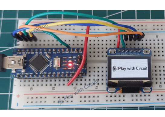
In this project, I interfaced both I2C and SPI versions of a 0.96-inch 128×64 OLED display with an Arduino Nano. Both displays use the SSD1306 controller, making them a good choice for experimenting with graphical displays in Arduino projects.
OLED Display Overview
The OLED used in this project has a 128×64 pixel resolution and operates from a typical 3.3V–5V supply. Unlike conventional LCDs, OLED pixels produce their own light, so no backlight is required. This provides high contrast, deep blacks, and good viewing angles.
The SSD1306 controller receives commands and display data from the Arduino and controls the OLED pixels. It includes 1KB of internal Graphic Display Data RAM (GDDRAM), which stores the pixel information used to refresh the display.
The memory is divided into 8 pages, with each page containing 128 columns. Each column controls 8 vertical pixels:
8 pages × 128 columns × 8 bits
Total = 8,192 bits
Total memory = 1KB
A 128×32 OLED uses only four pages of this memory, while the remaining memory remains unused.
I2C OLED Display
The I2C version is particularly convenient because it requires only two communication lines in addition to power. The module typically includes the SSD1306 controller, voltage regulation, filtering capacitors, I2C pull-up resistors, and configuration jumpers.
The SSD1306 supports two commonly used 7-bit I2C addresses: 0x3C and 0x3D. The selected address depends on the configuration of the address jumper on the module.
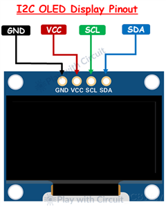
I2C Pin Connections
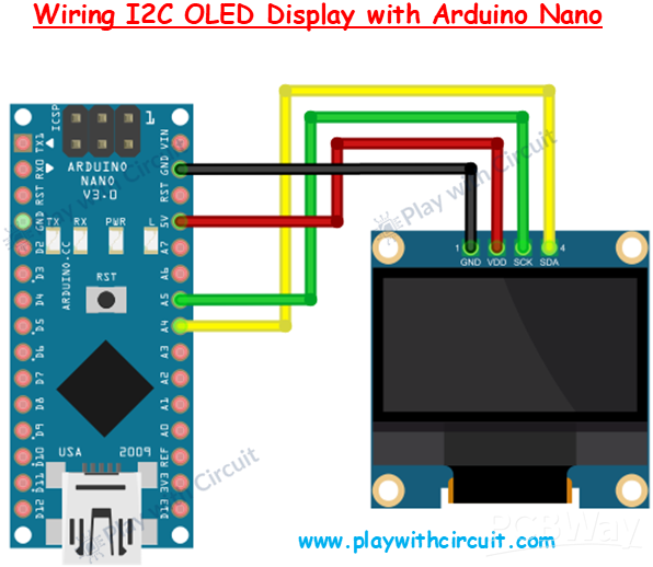
GND → Arduino Nano GND
VCC → Arduino Nano 5V
SCL → Arduino Nano A5
SDA → Arduino Nano A4
With only four connections, the I2C OLED leaves most of the Arduino's digital pins available for other peripherals.
SPI OLED Display
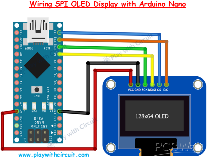
The SPI version uses additional pins because the communication interface has separate clock, data, and control signals. Unlike I2C, SPI uses direct push-pull signaling and therefore does not require the same pull-up resistor arrangement.
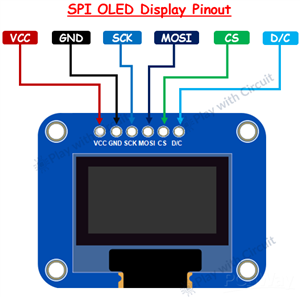
SPI Pin Connections
GND → Arduino Nano GND
VCC → Arduino Nano 5V
SCK → Arduino Nano D10
MOSI → Arduino Nano D9
CS → Arduino Nano D12
D/C → Arduino Nano D11
Here, SCK provides the SPI clock and MOSI transfers data from the Arduino to the OLED. The CS pin selects the display, while D/C determines whether the transmitted information is interpreted as a command or display data.
Hardware Required
The basic hardware setup consists of:
Arduino Nano R3
0.96-inch 128×64 SSD1306 I2C OLED
0.96-inch 128×64 SSD1306 SPI OLED
USB A-to-Mini-B cable
Jumper wires
5V power supply
For software, the project uses the Arduino IDE and the Adafruit SSD1306 library. The Adafruit GFX library can also be used for drawing text and graphical elements.
Working with Graphics
One of the biggest advantages of an OLED over a character LCD is pixel-level control. Once the display is initialized, the Arduino can be used to create different graphical elements such as:
Text and numbers
Lines
Rectangles
Circles
Icons
Bitmap images
Sensor graphs
Progress indicators
Simple animations
This makes a small SSD1306 OLED useful for projects that need more than basic character-based information.
I2C vs SPI OLED
Both interfaces can be used with the same SSD1306-based OLED concept, but they have different wiring requirements.
I2C is a good choice when fewer Arduino pins are available because it requires only SDA and SCL for communication.
SPI requires more connections but provides dedicated communication and control lines, making it useful when SPI is already being used in a project or when a dedicated display interface is preferred.
Conclusion
Interfacing an SSD1306 OLED with an Arduino Nano is a straightforward way to add a compact graphical interface to an embedded project. The I2C version keeps the wiring simple, while the SPI version provides dedicated communication and control signals.
With pixel-level control and support for text, shapes, images, and other graphics, these displays can be used in a wide range of Arduino-based projects.
For the complete project, source code, detailed OLED memory explanation, and additional examples, visit Play with Circuit:
Interfacing OLED Display with Arduino









Raspberry Pi 5 7 Inch Touch Screen IPS 1024x600 HD LCD HDMI-compatible Display for RPI 4B 3B+ OPI 5 AIDA64 PC Secondary Screen(Without Speaker)
BUY NOW

- Comments(0)
- Likes(0)
More by Rachana Jain
-
 Interfacing OLED Display with Arduino
OLED displays are a useful upgrade over traditional character LCDs when an Arduino project needs a c...
Interfacing OLED Display with Arduino
OLED displays are a useful upgrade over traditional character LCDs when an Arduino project needs a c...
-
 Long-Range Appliance Control Using Arduino and RYLR999 LoRa
Controlling an appliance wirelessly is straightforward when Wi-Fi is available, but things become mo...
Long-Range Appliance Control Using Arduino and RYLR999 LoRa
Controlling an appliance wirelessly is straightforward when Wi-Fi is available, but things become mo...
-
 GPS Tracker using Heltec WiFi LoRa 32 V4 and REYAX RYS352A GNSS Module
This browser-based GPS tracker combines the Heltec WiFi LoRa 32 V4 development board with the REYAX ...
GPS Tracker using Heltec WiFi LoRa 32 V4 and REYAX RYS352A GNSS Module
This browser-based GPS tracker combines the Heltec WiFi LoRa 32 V4 development board with the REYAX ...
-
 Arduino Stepper Motor Control Using 28BYJ-48 and ULN2003 Driver
This project demonstrates how to control the popular 28BYJ-48 5V stepper motor using an Arduino Uno ...
Arduino Stepper Motor Control Using 28BYJ-48 and ULN2003 Driver
This project demonstrates how to control the popular 28BYJ-48 5V stepper motor using an Arduino Uno ...
-
 Arduino Water Level Indicator Using Water Level Sensor
Monitoring water levels in tanks is important for preventing overflow and reducing water wastage. In...
Arduino Water Level Indicator Using Water Level Sensor
Monitoring water levels in tanks is important for preventing overflow and reducing water wastage. In...
-
 Arduino Servo Motor Control
Precise motion control is at the heart of many modern electronics projects—from robotic arms to came...
Arduino Servo Motor Control
Precise motion control is at the heart of many modern electronics projects—from robotic arms to came...
-
 Build a Long-Range Wireless Appliance Control System
Controlling electrical devices over long distances is often challenging, especially when internet co...
Build a Long-Range Wireless Appliance Control System
Controlling electrical devices over long distances is often challenging, especially when internet co...
-
 DHT11 and DHT22 Sensors with Arduino Uno
Temperature and humidity monitoring plays a crucial role in various applications, from smart home cl...
DHT11 and DHT22 Sensors with Arduino Uno
Temperature and humidity monitoring plays a crucial role in various applications, from smart home cl...
-
 Line Follower Robot using Arduino
A Line Follower Robot (LFR) is an autonomous robot that follows a predefined path, typically a black...
Line Follower Robot using Arduino
A Line Follower Robot (LFR) is an autonomous robot that follows a predefined path, typically a black...
-
 Ultrasonic Sensor HC-SR04 Interfacing with Arduino
The HC-SR04 Ultrasonic Sensor is a widely used and easy-to-implement sensor for distance measurement...
Ultrasonic Sensor HC-SR04 Interfacing with Arduino
The HC-SR04 Ultrasonic Sensor is a widely used and easy-to-implement sensor for distance measurement...
-
 Interfacing IR Sensor Module with Arduino Nano
In this project, we will learn how to interface an Infrared (IR) sensor module with an Arduino Nano....
Interfacing IR Sensor Module with Arduino Nano
In this project, we will learn how to interface an Infrared (IR) sensor module with an Arduino Nano....
-
Programmable Mist Maker - XIAO / QT PY Extension
2130 2 2 -
RadioHAT - Raspberry Pi radio development platform
1810 0 4 -
-
-
-
ARPS-2 – Arduino-Compatible Robot Project Shield for Arduino UNO
4021 0 6 -
A Compact Charging Breakout Board For Waveshare ESP32-C3
4758 3 8 -
AI-driven LoRa & LLM-enabled Kiosk & Food Delivery System
5571 2 2 -