


|
A000073Arduino
|
x 1 | |
|
|
Water Level Sensor Module |
x 1 | |
|
|
LEDs |
x 1 | |
|
|
Resistance 220KOhm |
x 1 | |
|
1115Adafruit Industries LLC
|
x 1 |
Arduino Water Level Indicator Using Water Level Sensor
Monitoring water levels in tanks is important for preventing overflow and reducing water wastage. In this project, we will interface a water level sensor with Arduino UNO to create a simple water level indicator system. The project can detect rising water levels and trigger alerts using LEDs and a buzzer.
This project is suitable for beginners who want to learn sensor interfacing with Arduino and build practical home automation applications.
How Water Level Sensor Works?
The water level sensor works by detecting the conductivity of water through exposed conductive traces present on the sensor board. The module contains alternating power traces and sensing traces arranged side by side.
When water touches the sensing area, it creates a conductive path between these traces. As more of the sensor gets submerged:
Conductivity increases
Resistance decreases
Output voltage changes proportionally
The sensor produces an analog output voltage that varies according to the amount of water detected. This analog signal is read by the Arduino to determine the water level.
Because of its simple operation and easy interfacing, the module is commonly used in:
Water tank monitoring
Overflow detection systems
Smart irrigation projects
Liquid level sensing applications
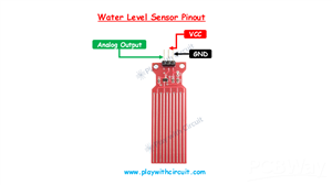
Water Level Sensor Pinout
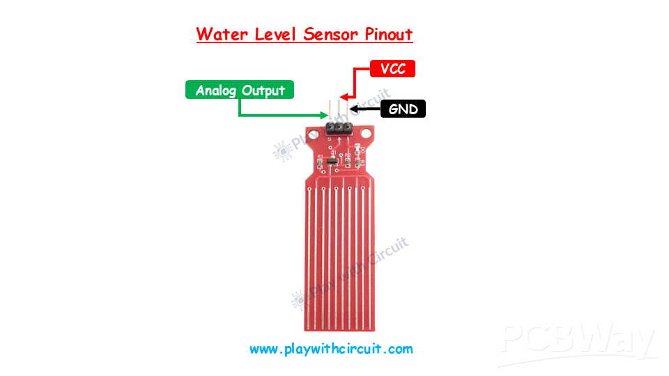
The water level sensor module has three interface pins.
VCC: The VCC pin powers the sensor module and should be connected to the 5V pin of the Arduino UNO.
GND: This pin provides the ground connection between the sensor and Arduino.
OUT: The OUT pin is the analog output of the sensor. It provides a varying voltage based on the detected water level and connects to the Arduino analog input pin.
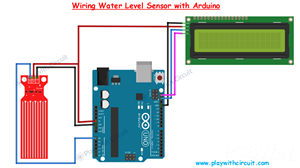
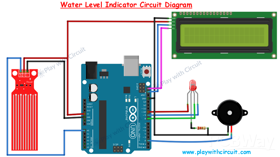
Connecting Water Level Sensor to Arduino
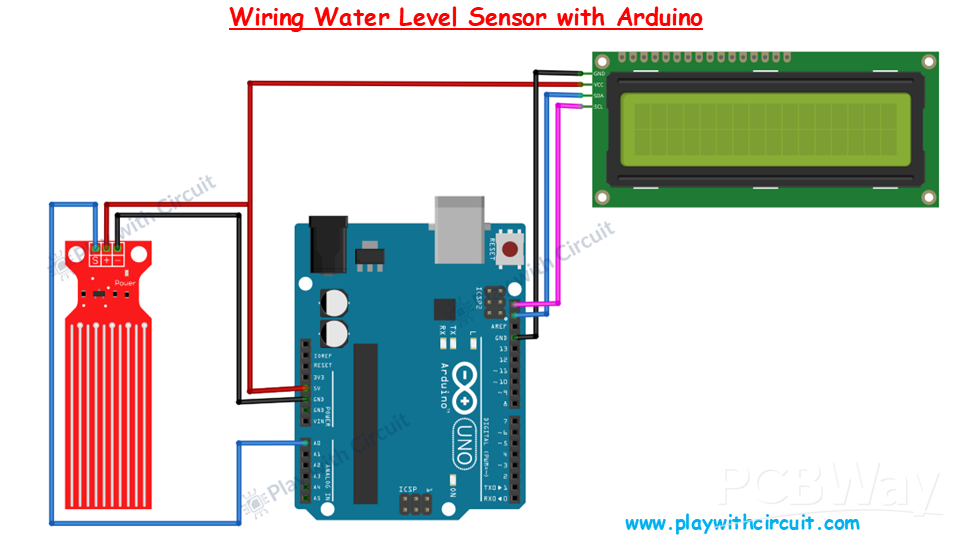
Interfacing the water level sensor with Arduino requires only a few connections. The VCC pin of the sensor is connected to the 5V pin of the Arduino UNO to supply operating power to the module. The GND pin of the sensor is connected to the GND pin of the Arduino to establish a common ground reference.
The sensor provides an analog output through the OUT pin, which should be connected to the A0 analog input pin of the Arduino UNO. The Arduino continuously reads the analog voltage from the sensor to determine the current water level.
As the water rises and covers more conductive traces, the sensor output changes accordingly, allowing the Arduino to monitor the liquid level effectively.
Connecting the I2C LCD Display
An optional I2C LCD display can be used to show live water level readings and system status. The LCD uses I2C communication, which minimizes wiring complexity.
The VCC pin of the LCD module is connected to the 5V pin of the Arduino, while the GND pin connects to Arduino ground. The SDA pin of the LCD is connected to the Arduino’s SDA pin, and the SCL pin is connected to the Arduino’s SCL pin.
This setup allows the Arduino to display sensor readings and warning messages directly on the LCD screen.
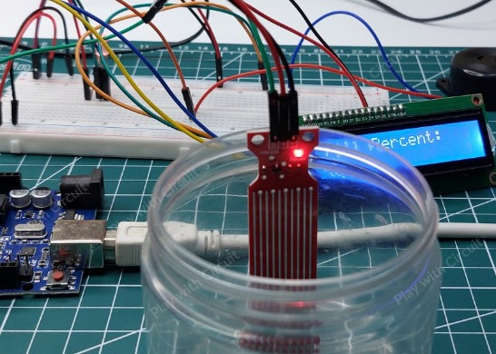
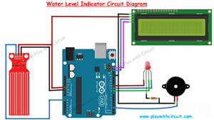
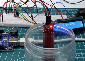
Water Level Indicator Project
In this project, the Arduino continuously reads data from the water level sensor and compares it with predefined threshold values.
Based on the measured water level:
LEDs can indicate low, medium, or high water levels
A buzzer can alert the user when the tank becomes full
LCD can display real-time water level information
The system provides a simple and effective solution for household water tank monitoring applications.
Conclusion
This Arduino water level indicator project demonstrates how a simple analog water level sensor can be used to monitor liquid levels efficiently. The project is easy to build and can be further expanded into advanced automation systems with relays, IoT connectivity, or wireless monitoring features.
For the complete circuit diagram, source code, and detailed tutorial, check out the original article:
How does a Water Level Sensor Work and Interface it with Arduino
/*
Interfacing Water Level Sensor with Arduino UNO using Analog Output pin of Module
by www.playwithcircuit.com
Using this code we will know the Analog Value when water level is very low and when it is very high.
*/
#include <LiquidCrystal_I2C.h>  // Library to Run I2C LCD
// define the size of filter array
#define FILTER_SIZE 20
// Set the LCD address to 0x27 for a 16 chars and 2 line display
LiquidCrystal_I2C lcd(0x27, 16, 2);
// Define the analog pin for the soil moisture sensor
const int WaterSensorPin = A0;
// Analog Value filter
int Filter(int sensorValue);
void setup() {
  // initialize the lcd
  lcd.init();
  // Turn on the Backlight
  lcd.backlight();
  // Clear the display buffer
  lcd.clear();
  // Print a message to the LCD
  lcd.setCursor(0, 0);
  lcd.print("Analog Value:");
}
void loop() {
  // Variable to store sensor values
  int sensorValue;
  // Variable to store filtered values
  int filteredValue;
  // Read the value from the soil moisture sensor
  sensorValue = analogRead(WaterSensorPin);
  filteredValue = Filter(sensorValue);
  // Display the filtered Analog Value on the LCD
  lcd.setCursor(0, 1);
  lcd.print(filteredValue);
  // Clear Previous Data
  lcd.print("   ");
  // Wait for 50ms before the next loop
  delay(50);
}
// Averaging filter to filter Analog Values
int Filter(int sensorValue) {
  static int analogArray[FILTER_SIZE] = { 0 };
  int filteredValue = 0;
  int i;
  // Shift the Elemnent removing the oldest value stored at index 0
  for (i = 0; i < (FILTER_SIZE - 1); i++) {
    analogArray[i] = analogArray[i + 1];
  }
  // Put the current value in the last element of Array i.e at index FILTER_SIZE-1
  analogArray[FILTER_SIZE-1] = sensorValue;
  for (i = 0; i < FILTER_SIZE; i++) {
    filteredValue += analogArray[i];
  }
  // Return Filtered Analog Value
  return (filteredValue / FILTER_SIZE);
}
Arduino Water Level Indicator Using Water Level Sensor


Raspberry Pi 5 7 Inch Touch Screen IPS 1024x600 HD LCD HDMI-compatible Display for RPI 4B 3B+ OPI 5 AIDA64 PC Secondary Screen(Without Speaker)
BUY NOW

- Comments(1)
- Likes(0)
More by Rachana Jain
-
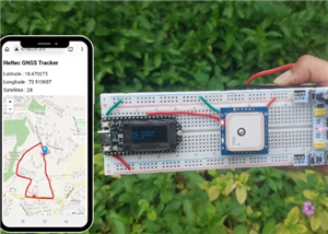 GPS Tracker using Heltec WiFi LoRa 32 V4 and REYAX RYS352A GNSS Module
This browser-based GPS tracker combines the Heltec WiFi LoRa 32 V4 development board with the REYAX ...
GPS Tracker using Heltec WiFi LoRa 32 V4 and REYAX RYS352A GNSS Module
This browser-based GPS tracker combines the Heltec WiFi LoRa 32 V4 development board with the REYAX ...
-
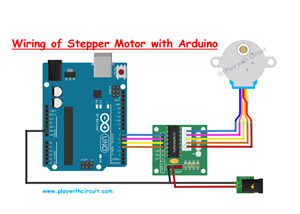 Arduino Stepper Motor Control Using 28BYJ-48 and ULN2003 Driver
This project demonstrates how to control the popular 28BYJ-48 5V stepper motor using an Arduino Uno ...
Arduino Stepper Motor Control Using 28BYJ-48 and ULN2003 Driver
This project demonstrates how to control the popular 28BYJ-48 5V stepper motor using an Arduino Uno ...
-
 Arduino Water Level Indicator Using Water Level Sensor
Monitoring water levels in tanks is important for preventing overflow and reducing water wastage. In...
Arduino Water Level Indicator Using Water Level Sensor
Monitoring water levels in tanks is important for preventing overflow and reducing water wastage. In...
-
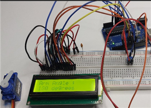 Arduino Servo Motor Control
Precise motion control is at the heart of many modern electronics projects—from robotic arms to came...
Arduino Servo Motor Control
Precise motion control is at the heart of many modern electronics projects—from robotic arms to came...
-
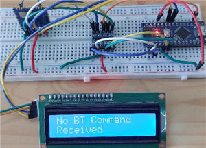 Build a Long-Range Wireless Appliance Control System
Controlling electrical devices over long distances is often challenging, especially when internet co...
Build a Long-Range Wireless Appliance Control System
Controlling electrical devices over long distances is often challenging, especially when internet co...
-
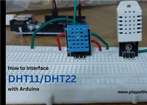 DHT11 and DHT22 Sensors with Arduino Uno
Temperature and humidity monitoring plays a crucial role in various applications, from smart home cl...
DHT11 and DHT22 Sensors with Arduino Uno
Temperature and humidity monitoring plays a crucial role in various applications, from smart home cl...
-
 Line Follower Robot using Arduino
A Line Follower Robot (LFR) is an autonomous robot that follows a predefined path, typically a black...
Line Follower Robot using Arduino
A Line Follower Robot (LFR) is an autonomous robot that follows a predefined path, typically a black...
-
 Ultrasonic Sensor HC-SR04 Interfacing with Arduino
The HC-SR04 Ultrasonic Sensor is a widely used and easy-to-implement sensor for distance measurement...
Ultrasonic Sensor HC-SR04 Interfacing with Arduino
The HC-SR04 Ultrasonic Sensor is a widely used and easy-to-implement sensor for distance measurement...
-
 Interfacing IR Sensor Module with Arduino Nano
In this project, we will learn how to interface an Infrared (IR) sensor module with an Arduino Nano....
Interfacing IR Sensor Module with Arduino Nano
In this project, we will learn how to interface an Infrared (IR) sensor module with an Arduino Nano....
-
Programmable Mist Maker - XIAO / QT PY Extension
1066 2 1 -
RadioHAT - Raspberry Pi radio development platform
878 0 2 -
-
-
-
-
ARPS-2 – Arduino-Compatible Robot Project Shield for Arduino UNO
3331 0 6 -
A Compact Charging Breakout Board For Waveshare ESP32-C3
3940 3 8 -
AI-driven LoRa & LLM-enabled Kiosk & Food Delivery System
4326 2 2


