


|
|
Arduino Uno board |
x 1 | |
|
|
Micro servo motor |
x 1 | |
|
|
Generic Jumper WiresVarious
|
x 1 | |
|
|
10kΩ potentiometer |
x 1 | |
|
|
16x2 LCD display |
x 1 | |
|
|
220Ω resistor |
x 1 | |
|
4474Adafruit Industries LLC
|
x 1 |

|
arduino IDEArduino
|
Arduino Servo Motor Control
Precise motion control is at the heart of many modern electronics projects—from robotic arms to camera stabilizers. One of the simplest ways to achieve this is by using a servo motor with a microcontroller like the Arduino Uno.
In this project, you’ll learn how to control a servo motor’s position using Arduino. Whether you're a student exploring embedded systems or a In this guide, we’ll not only interface a servo motor with Arduino but also take it a step further by briefly building a simple servo tester. This helps you verify whether a servo is working correctly before integrating it into larger systems.
Servo Motor Overview and Working
A servo motor is a compact motor designed for controlled angular movement rather than continuous rotation. Inside, it combines a DC motor, gears, and a feedback mechanism (usually a potentiometer), enabling it to move to a specific angle and hold that position.
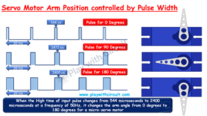
Servo motors operate based on Pulse Width Modulation (PWM). Instead of varying voltage, the control happens by changing the duration of a pulse signal.
Here’s the idea:
A short pulse (~0.5 ms) → rotates shaft to 0°
A medium pulse (~1.5 ms) → moves to 90°
A longer pulse (~2.4 ms) → reaches 180°
The Arduino generates these PWM signals, and the servo’s internal circuitry continuously adjusts its position based on the incoming pulse width. This feedback-driven mechanism ensures accurate positioning.
Servo Motor Pinout
VCC: Supplies power (typically 5V)
GND: Ground reference
Signal: Receives control signals from Arduino
This simple 3-wire interface makes servos extremely easy to integrate into projects.
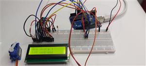
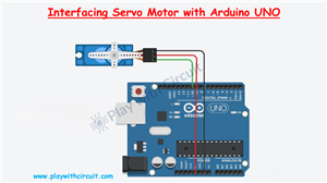
Hardware Setup and Connections
Connecting the servo to Arduino is straightforward:
Connect the VCC of the servo to the 5V pin on Arduino
Connect the GND pin of servo to the GND pin of Arduino
Connect the signal wire to a PWM pin 10
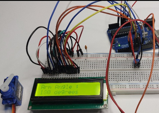
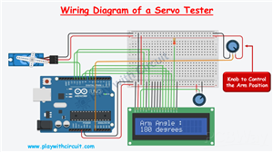
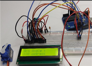
Building a Simple Servo Tester with Arduino
A servo tester is a handy tool used to check, calibrate, and debug servo motors before using them in actual projects. Instead of guessing if a servo is faulty, you can quickly validate its response.
How It Works:
A 10k potentiometer acts as a manual control knob. Its middle pin connects to Analog pin A0. As you rotate the knob, Arduino reads the value and adjusts the servo angle. A 16x2 LCD displays the current angle.
💡 Practical Insight:
This tester is extremely useful when working with multiple servos in robotics or automation projects—it saves debugging time and ensures reliability.
Video
Conclusion
Learning how to control a servo motor is a key milestone in embedded systems. By combining it with a simple tester setup, you not only control motion but also gain the ability to validate and calibrate components—a skill used in real-world engineering workflows.
For complete step-by-step instructions, Arduino code, and detailed servo motor testing guide, check the full tutorial here:
https://playwithcircuit.com/how-to-interface-servo-motor-with-arduino/
/*
Interfacing Micro Servo Motor with Arduino without using servo library
by www.playwithcircuit.com
*/
#include <Servo.h>
#define SERVO_PIN   10
Servo myservo;                          // create servo object to control a servo
int pos = 0;                            // variable to store the servo position
void setup() {
  myservo.attach(SERVO_PIN);            // attaches the servo on pin 9 to the servo object
  myservo.write(pos);                   // go to position zero first
  delay(2000);                          // wait for some time
}
void loop() {
  delay(1000);                          // delay of 1 second before start
  for (pos = 0; pos <= 180; pos += 1) { // goes from 0 degrees to 180 degrees in steps of 1 degree
    myservo.write(pos);                 // tell servo to go to position in variable 'pos'
    delay(15);                          // waits 15 ms for the servo to reach the position
  }
  delay(1000);                          // delay of 1 second before changing direction of rotation
  for (pos = 180; pos >= 0; pos -= 1) { // goes from 180 degrees to 0 degrees
    myservo.write(pos);                 // tell servo to go to position in variable 'pos'
    delay(15);                          // waits 15 ms for the servo to reach the position
  }
}
Arduino Servo Motor Control


Raspberry Pi 5 7 Inch Touch Screen IPS 1024x600 HD LCD HDMI-compatible Display for RPI 4B 3B+ OPI 5 AIDA64 PC Secondary Screen(Without Speaker)
BUY NOW

- Comments(1)
- Likes(0)
More by Rachana Jain
-
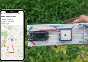 GPS Tracker using Heltec WiFi LoRa 32 V4 and REYAX RYS352A GNSS Module
This browser-based GPS tracker combines the Heltec WiFi LoRa 32 V4 development board with the REYAX ...
GPS Tracker using Heltec WiFi LoRa 32 V4 and REYAX RYS352A GNSS Module
This browser-based GPS tracker combines the Heltec WiFi LoRa 32 V4 development board with the REYAX ...
-
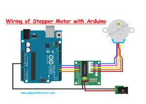 Arduino Stepper Motor Control Using 28BYJ-48 and ULN2003 Driver
This project demonstrates how to control the popular 28BYJ-48 5V stepper motor using an Arduino Uno ...
Arduino Stepper Motor Control Using 28BYJ-48 and ULN2003 Driver
This project demonstrates how to control the popular 28BYJ-48 5V stepper motor using an Arduino Uno ...
-
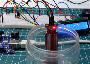 Arduino Water Level Indicator Using Water Level Sensor
Monitoring water levels in tanks is important for preventing overflow and reducing water wastage. In...
Arduino Water Level Indicator Using Water Level Sensor
Monitoring water levels in tanks is important for preventing overflow and reducing water wastage. In...
-
 Arduino Servo Motor Control
Precise motion control is at the heart of many modern electronics projects—from robotic arms to came...
Arduino Servo Motor Control
Precise motion control is at the heart of many modern electronics projects—from robotic arms to came...
-
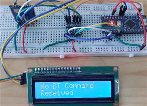 Build a Long-Range Wireless Appliance Control System
Controlling electrical devices over long distances is often challenging, especially when internet co...
Build a Long-Range Wireless Appliance Control System
Controlling electrical devices over long distances is often challenging, especially when internet co...
-
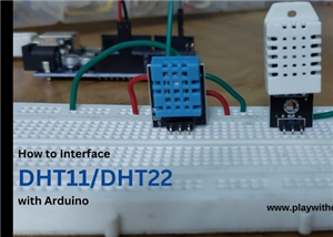 DHT11 and DHT22 Sensors with Arduino Uno
Temperature and humidity monitoring plays a crucial role in various applications, from smart home cl...
DHT11 and DHT22 Sensors with Arduino Uno
Temperature and humidity monitoring plays a crucial role in various applications, from smart home cl...
-
 Line Follower Robot using Arduino
A Line Follower Robot (LFR) is an autonomous robot that follows a predefined path, typically a black...
Line Follower Robot using Arduino
A Line Follower Robot (LFR) is an autonomous robot that follows a predefined path, typically a black...
-
 Ultrasonic Sensor HC-SR04 Interfacing with Arduino
The HC-SR04 Ultrasonic Sensor is a widely used and easy-to-implement sensor for distance measurement...
Ultrasonic Sensor HC-SR04 Interfacing with Arduino
The HC-SR04 Ultrasonic Sensor is a widely used and easy-to-implement sensor for distance measurement...
-
 Interfacing IR Sensor Module with Arduino Nano
In this project, we will learn how to interface an Infrared (IR) sensor module with an Arduino Nano....
Interfacing IR Sensor Module with Arduino Nano
In this project, we will learn how to interface an Infrared (IR) sensor module with an Arduino Nano....
-
Programmable Mist Maker - XIAO / QT PY Extension
1062 2 1 -
RadioHAT - Raspberry Pi radio development platform
874 0 2 -
-
-
-
-
ARPS-2 – Arduino-Compatible Robot Project Shield for Arduino UNO
3327 0 6 -
A Compact Charging Breakout Board For Waveshare ESP32-C3
3934 3 8 -
AI-driven LoRa & LLM-enabled Kiosk & Food Delivery System
4323 2 2


