


|
Soldering iron (generic) |
|

|
Solder Wire, Lead Free |
|

|
arduino IDEArduino
|
|
|
|
Polycam |
How to Build a Motorized 3D Scanning Turntable for Your Phone
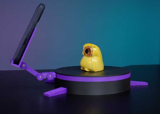
In this project, I’ll show you how to make a simple motorized turntable for 3D scanning. It has three main parts: a fixed top plate for placing the object, a rotating middle plate powered by a stepper motor, and a base that holds all the components. The top and base plates are connected and stay in place, while the middle plate rotates independently.
To ensure smooth rotation, I’ve added bearings that help the middle plate move more easily. For scanning, I used an iOS app, but you can choose any software. The goal is to show you how to build this turntable step by step. Let’s get started!
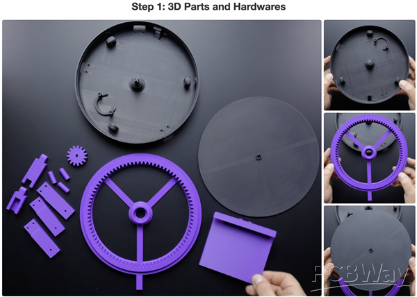
This project consists of three main 3D-printed parts. The first part is the base, which includes three bearing slots, a stepper motor mount, three mounting leg slots on the sides, and a slot for a power switch.
The second part is the gear plate. It has a bearing slot in the center and is the only moving part responsible for rotation. On its side, there is a mounting point for attaching a phone holder.
The third part is the top plate, where the object to be scanned is placed. This piece is fixed directly from its center to the base plate, ensuring that both remain completely stationary.
Additionally, the project includes a small gear that attaches to the stepper motor, three pins to secure the bearings, and three mounting legs. There are also extension arms and a holder plate for the phone.
If you don’t have a 3D printer, you can use PCBWay’s 3D printing service to get these parts. The STL files are available for free:
https://www.pcbway.com/project/shareproject/DIY_Motorized_3D_Scanning_Turntable_32ec4cb1.html
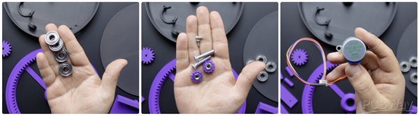
On the hardware side, four 608 ZZ bearings are needed to ensure smoother rotation. A few bolts and nuts are required to secure the stepper motor and phone holder. Lastly, a popular 28BYJ-48 hobby stepper motor will be used.
We will cover the electronic components in the next steps. Now, let’s start building by securing the bearings to the base.
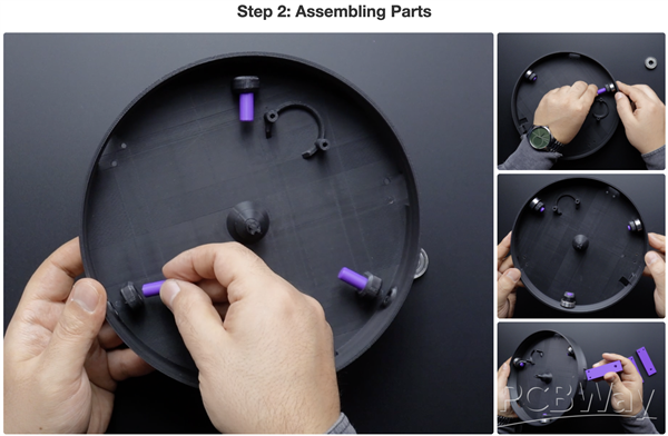
- Insert the pin pieces into the pin slots in the base piece, but not completely.
- Then insert the bearings into the bearing housing and press the pins fully into the slots.
- Then insert the 3 foot pieces into the foot slots in the base. It is tight enough, but you can fix it using M3 bolts if you wish.
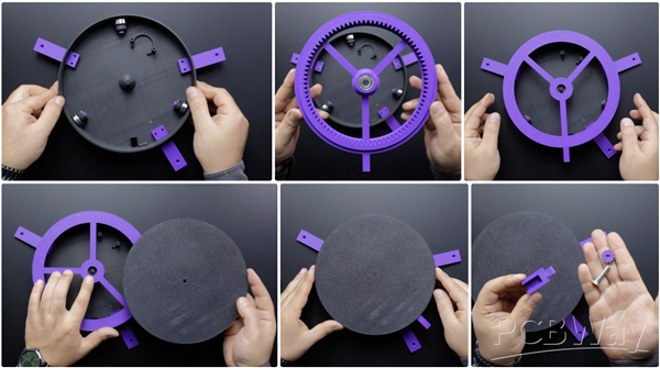
- Take the gear part and press one bearing into the bearing slot in the centre of the gear part.
- Place the gear part on top of the base part.
- Place the top plate so that the female slot in the top plate part matches the male slot in the centre of the base part.
- Finally, insert the phone holder arms and stand and secure with M5 bolts and nuts.
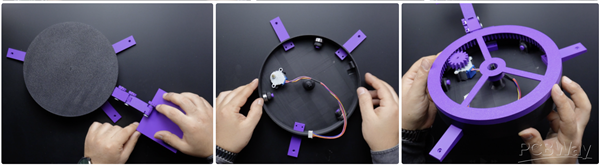
The assembly of all 3D parts was completed. Manually rotate the gear part in the middle layer a few turns, if it rotates smoothly, remove the top plate and gear part, place the stepper motor in the slot and fix it with M3 bolts. Then insert the stepper motor gear. that's all! Now let's move on to the electronic step.
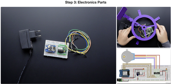
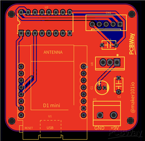
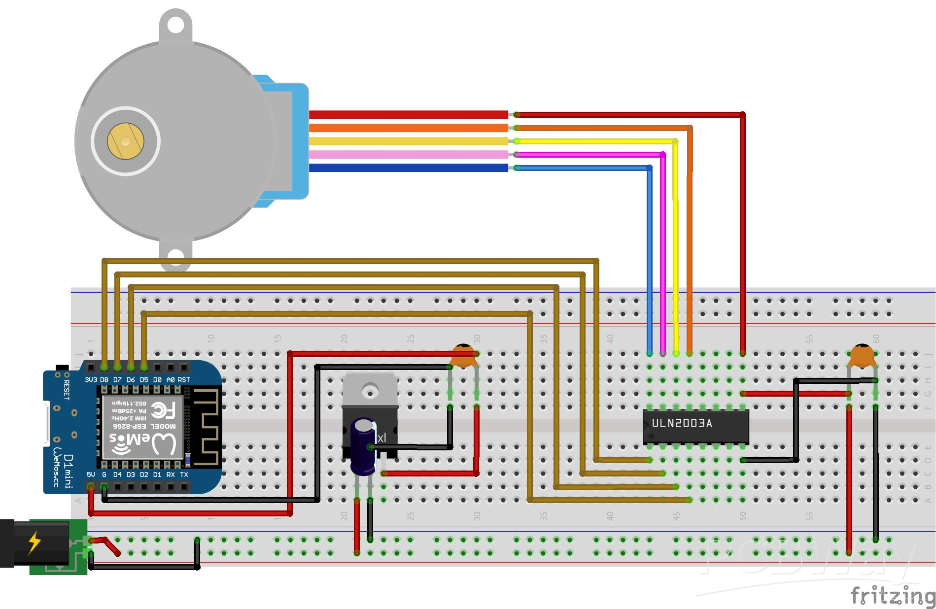
Looking at the electronics, this project uses an ESP8266 development board, allowing the rotating table to be controlled wirelessly if needed. For the stepper motor driver, the popular ULN2003 is used. A breadboard and a few jumper wires are needed to set up the circuit.
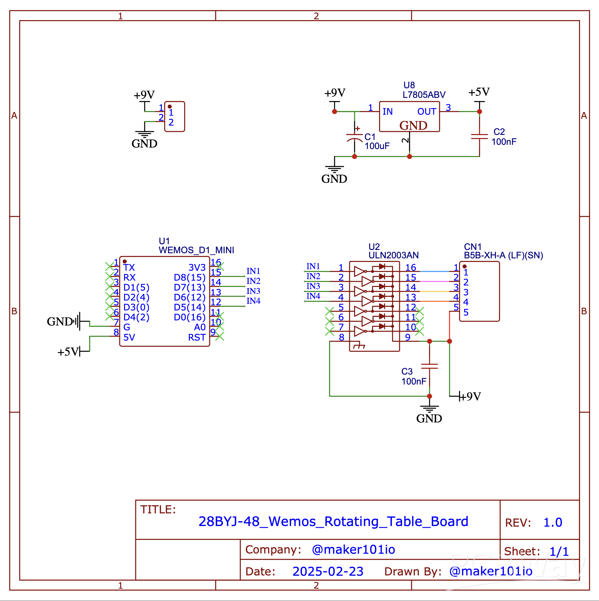
To power the system, a 9-Volts adapter will be used, along with a few capacitors and a voltage regulator to provide 5-Volts to the development board. A circuit diagram has been shared to help you build the breadboard setup. However, placing the breadboard inside the base may interfere with the rotating gear, and loose wires could cause disconnections or short circuits.
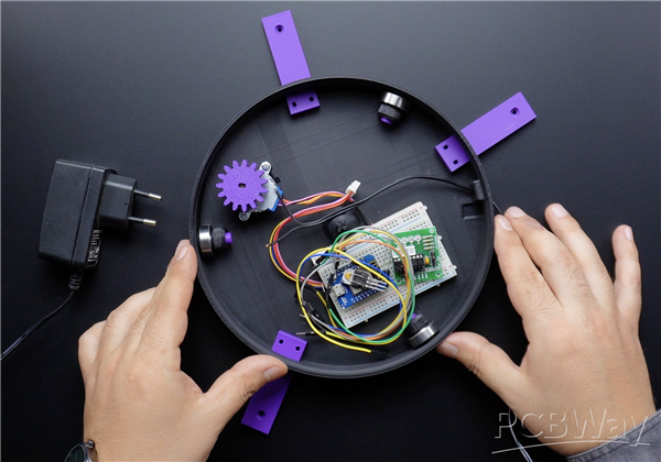
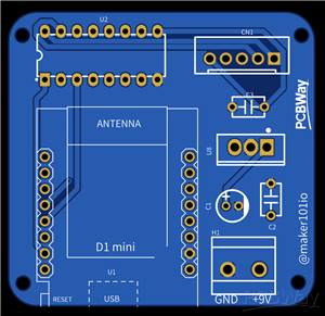
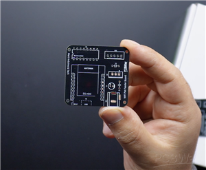
For this reason, a custom PCB will be used instead. A previously designed PCB is a perfect fit for this project. The power connector on the PCB has been updated, and the latest version is now available.
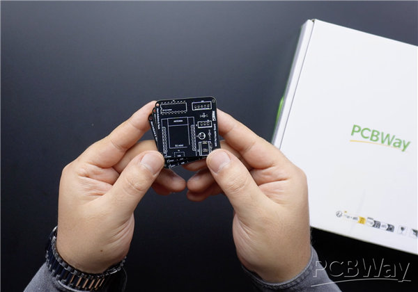
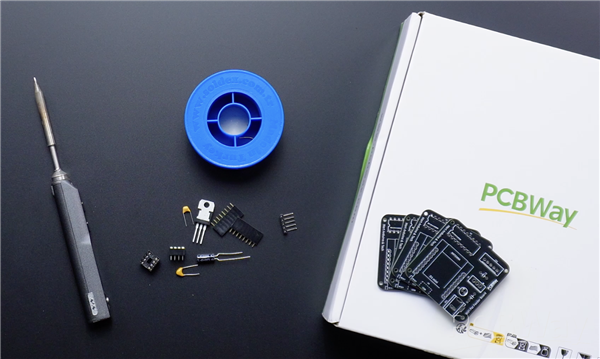
Now, gather the necessary components and soldering tools—let’s start soldering!
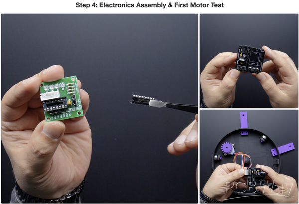
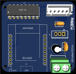
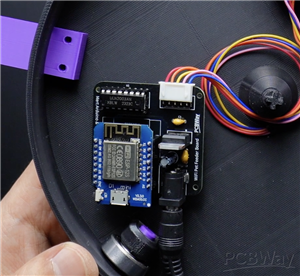
If the soldering process for the PCB is complete, take the stepper motor driver chip and insert it into the board. Make sure to align it correctly—the notch on the chip should match the notch on the PCB.
Next, place the PCB onto the base plate and connect the stepper motor. Now, it’s time to set up the power connection. A 2-pin switch is used to turn the circuit on and off, but this is optional—you can also connect the power adapter directly.
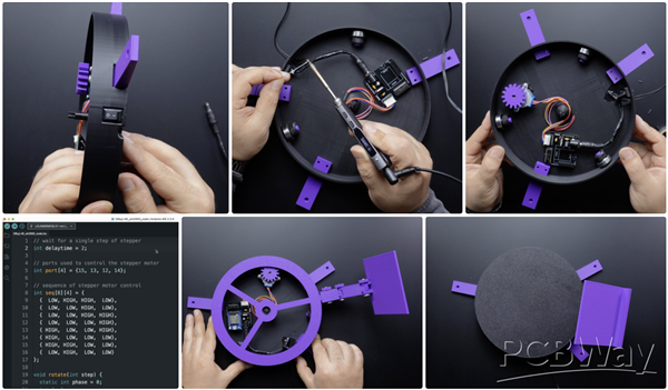
Since this project uses an older PCB version, a barrel jack connection will be used. However, the updated PCB version includes a 2-pin terminal block for easier wiring. Cut the power cable to the appropriate length, connect it to the switch, and secure it by soldering. To prevent short circuits, I used electrical tape, but heat shrink tubing is recommended for a more secure connection.
Once the circuit is set up, we can move on to programming. Open the provided source code and update the pin numbers according to your motor connections. This is a simple code that makes the stepper motor rotate in one direction. After uploading the code to the board, insert it into the PCB and power it up.
On the first test, the motor stalled and made some noise. If this happens, try reversing the motor connections. You can either change the pin sequence in the code or simply flip the motor connector.
Now it works! The motor is running smoothly. Next, place the gear plate in the center. If the rotation is still smooth, attach the top plate as well.
As you can see, the rotating table is now fully functional and spins effortlessly. In the next step, we will explore the application side.
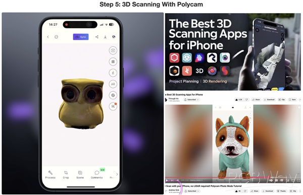
While researching 3D scanning apps for iPhone, I came across a great video on the Through Iris YouTube channel. This video reviews multiple apps, and for this project, I chose Polycam. Since the main focus of this project is the motorized rotating table, I will cover only the basic use of the app. If you also want to use Polycam, I recommend watching a step-by-step guide by Andrew Sink on YouTube.
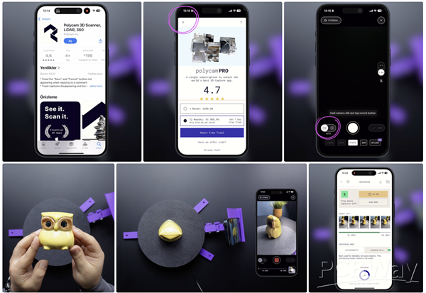
After downloading the app, you can close the subscription page to continue testing it for free. In the scanning interface, you will find two capture modes. In Manual Mode, you need to press the shutter button for each capture, while in Auto Mode, you only need to press the Record button at the start and end of the scan.
Now, place the object you want to scan at the exact center of the rotating table. Then, mount your phone onto the holder, press the Record button, and start the rotating table. The app will automatically capture and save images at regular intervals as the table rotates. You can also reduce the motor step speed if needed—this can improve the scan quality. Based on the current step speed in the source code, a full rotation captures about 60 images.
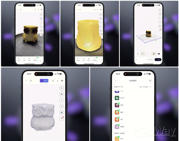
Once the scan is complete, stop the recording and press Upload & Process in the app to finalize the scan. Now, your 3D mesh is ready! Looking at the results, I’m actually surprised by how well it turned out, even with a quick test scan. With more precise settings, I’m sure the details can be even better.
Finally, the scanned object can be exported in multiple file formats.
And that’s it! Another project completed. If you have any ideas or feedback, feel free to share them in the comments. Thanks for reading!
How to Build a Motorized 3D Scanning Turntable for Your Phone
*PCBWay community is a sharing platform. We are not responsible for any design issues and parameter issues (board thickness, surface finish, etc.) you choose.


Raspberry Pi 5 7 Inch Touch Screen IPS 1024x600 HD LCD HDMI-compatible Display for RPI 4B 3B+ OPI 5 AIDA64 PC Secondary Screen(Without Speaker)
BUY NOW


- Comments(0)
- Likes(20)
- 3 USER VOTES
- YOUR VOTE 0.00 0.00

-
8design
-
9usability
-
9creativity
-
10content
-
10design
-
9usability
-
10creativity
-
10content

-
10design
-
9usability
-
9creativity
-
10content
More by MERT KILIC
-
 3D Printed Theo Jansen Style Octopod Robot (Arduino Based)
Hi everyone! In this project, I will show you an amazing eight-legged robot in the Octopod style! It...
3D Printed Theo Jansen Style Octopod Robot (Arduino Based)
Hi everyone! In this project, I will show you an amazing eight-legged robot in the Octopod style! It...
-
 Creative Modular LED Lighting with Magnetic Pogo Pins & Wi-Fi Control
Hi everyone! Welcome to my latest project: a modular, plug-in LED lighting system that is as fun as ...
Creative Modular LED Lighting with Magnetic Pogo Pins & Wi-Fi Control
Hi everyone! Welcome to my latest project: a modular, plug-in LED lighting system that is as fun as ...
-
 Build a simple 3D printed CNC plotter machine
Hi friends, do you remember this Mini CNC Plotter machine that uses hobby stepper motors and a few 3...
Build a simple 3D printed CNC plotter machine
Hi friends, do you remember this Mini CNC Plotter machine that uses hobby stepper motors and a few 3...
-
 Circuit Activity Board - Educational Electronics
Circuit Activity Board – A Hands-On Project to Learn Basic ElectronicsIn this project, we're going t...
Circuit Activity Board - Educational Electronics
Circuit Activity Board – A Hands-On Project to Learn Basic ElectronicsIn this project, we're going t...
-
 Build a Simple 3D Wall Lighting
Hi friends, this project shows how to make and control 3D hexagonal LED lighting panels. The project...
Build a Simple 3D Wall Lighting
Hi friends, this project shows how to make and control 3D hexagonal LED lighting panels. The project...
-
 Robot Sumo Board
Robot-sumo, or pepe-sumo, is a sport in which two robots attempt to push each other out of a circle ...
Robot Sumo Board
Robot-sumo, or pepe-sumo, is a sport in which two robots attempt to push each other out of a circle ...
-
 ESP32 Mecanum Wheels Robot and Bluetooth Gamepad Controller
In this project we will see how to make an ESP32 Mecanum Wheels Robot which is capable of moving in ...
ESP32 Mecanum Wheels Robot and Bluetooth Gamepad Controller
In this project we will see how to make an ESP32 Mecanum Wheels Robot which is capable of moving in ...
-
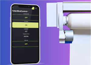
 DIY Motorized WiFi Roller Blind - ESP8266 & Blynk
In this project we will see how to control a roller blind via a smartphone application. The reason w...
DIY Motorized WiFi Roller Blind - ESP8266 & Blynk
In this project we will see how to control a roller blind via a smartphone application. The reason w...
-
 Pet Feeder Controlled Via WiFi - ESP8266
How It Works?As you can see, a 3D design was used for the pet feeder. ESP8266-based Wemos D1 Mini bo...
Pet Feeder Controlled Via WiFi - ESP8266
How It Works?As you can see, a 3D design was used for the pet feeder. ESP8266-based Wemos D1 Mini bo...
-
 ESP8266 Two Wheel Robot (NodeMCU and Stepper Motor)
Generally, robot cars are built on a chassis with 2 DC motor wheels and a bovine wheel. While surfin...
ESP8266 Two Wheel Robot (NodeMCU and Stepper Motor)
Generally, robot cars are built on a chassis with 2 DC motor wheels and a bovine wheel. While surfin...
-
 3D Printed Rotating Table Board with Arduino Nano and 28BYJ-48 Stepper Motor
This project shows how to make a 3D printed Rotating Table using Arduino and a hobby stepper motor. ...
3D Printed Rotating Table Board with Arduino Nano and 28BYJ-48 Stepper Motor
This project shows how to make a 3D printed Rotating Table using Arduino and a hobby stepper motor. ...
-
 Hand Gesture Controller for Robotic
The hand gesture controller makes it possible to control applicat...
Hand Gesture Controller for Robotic
Hand Gesture Controller for RoboticThe hand gesture controller makes it possible to control applicat...
-
 How To Make DIY Remote Control Hoverboat at Home
In this video, I showed you how to make your own hoverboat from materials available at home and chea...
How To Make DIY Remote Control Hoverboat at Home
In this video, I showed you how to make your own hoverboat from materials available at home and chea...
-
 How to Make DIY Arduino Gesture Control Robot at Home
Parts Required for Receiver (Tank):1) Robot Tank Chassis - https://bit.ly/3j8y2Q52) Arduino Nano V3 ...
How to Make DIY Arduino Gesture Control Robot at Home
Parts Required for Receiver (Tank):1) Robot Tank Chassis - https://bit.ly/3j8y2Q52) Arduino Nano V3 ...
-
 DIY Circuit Activty Board with Paperclips | MAKER | STEM
You can be creative and design your own circuit and add different sensors (other LEDs...). The idea ...
DIY Circuit Activty Board with Paperclips | MAKER | STEM
You can be creative and design your own circuit and add different sensors (other LEDs...). The idea ...
-
 ATtiny85 Wearable Activity Tracking Watch
How to make the wearable activity tracking watch? This is a wearable gadget designed to vibrate when...
ATtiny85 Wearable Activity Tracking Watch
How to make the wearable activity tracking watch? This is a wearable gadget designed to vibrate when...
-
 DIY Motorized Roller Blind with ESP32-S3 | WiFi Control, 3D Printed Gear & Blynk Cloud
This project is an updated version of my previous Motorized Roller Blind, which reached nearly 300,0...
DIY Motorized Roller Blind with ESP32-S3 | WiFi Control, 3D Printed Gear & Blynk Cloud
This project is an updated version of my previous Motorized Roller Blind, which reached nearly 300,0...
-
 How to Build a Motorized 3D Scanning Turntable for Your Phone
In this project, I’ll show you how to make a simple motorized turntable for 3D scanning. It has thre...
How to Build a Motorized 3D Scanning Turntable for Your Phone
In this project, I’ll show you how to make a simple motorized turntable for 3D scanning. It has thre...
-
-
ARPS-2 – Arduino-Compatible Robot Project Shield for Arduino UNO
2511 0 5 -
A Compact Charging Breakout Board For Waveshare ESP32-C3
2963 3 8 -
AI-driven LoRa & LLM-enabled Kiosk & Food Delivery System
3174 2 1 -
-
-
-
ESP32-C3 BLE Keyboard - Battery Powered with USB-C Charging
3233 0 2


