


|
arduino IDEArduino
|
|
|
|
Blynk Cloudhttps://blynk.cloud/
|
DIY Motorized Roller Blind with ESP32-S3 | WiFi Control, 3D Printed Gear & Blynk Cloud
This project is an updated version of my previous Motorized Roller Blind, which reached nearly 300,000 views. After reviewing user feedback, I realized that several mechanical and electronic parts could be improved.
In the original version, installing the 3D gear mechanism model and electronics enclosure required drilling holes into the blind profile and the wall. To eliminate this, I redesigned the entire system with a focus on tool-free installation and compact integration.
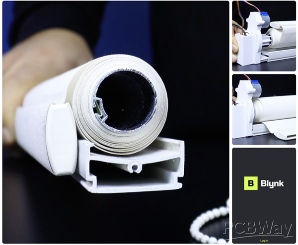
The biggest change is combining the 3D gear mechanism model and the electronics enclosure into a single, slide-in mechanical structure.
Supplies
This project was designed using widely available and affordable components.
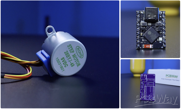
Main electronic components:
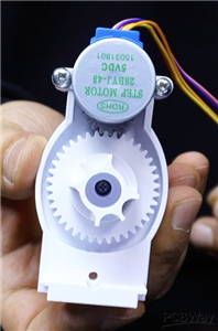
- 28BYJ-48 5V Stepper Motor – chosen for its availability and low cost
- ESP32-S3 Mini Board – selected for its compact size and built-in WiFi & Bluetooth
- ULN2003 Driver – DIP module for breadboard circuit or SMT version for the PCB
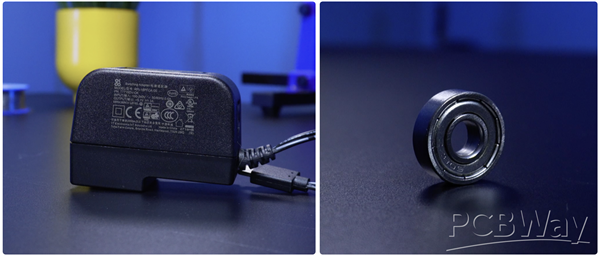
- 5V 2A Power Supply – provides enough current for stable motor operation
If a custom-designed PCB is to be used, all necessary components are provided in the circuit step.
Mechanical components:
- 608ZZ Ball Bearing – reduces load on the motor shaft
- Custom 3D-printed gears and mounts
- M3 screws, bolts, and nuts for blind gear assembly
- 2 × M4 bolts to secure the 28BYJ-48 motor
If you are going to build a breadboard circuit, you will need a mini breadboard and jumper wires. Or you can purchase a custom-designed PCB and easily incorporate it into your project.
3D Design and STL Models
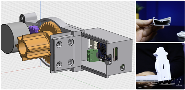
In the original version, it was necessary to drill holes in the roller blind profile to mount the 3D gear mechanism model and secure the 3D gear mechanism socket with screws. The same applied to the electronic enclosure, which had to be mounted to the wall with screws.
To eliminate these steps, I redesigned several parts in the 3D model:
- The electronic enclosure and motor gear mechanism are now integrated into a single modular design. This allows the enclosure to be securely locked into place by sliding it into position without drilling or using screws.
- The 3D gear mechanism model has been redesigned. It is now fully compatible with the original slot of the roller blind metal profile, meaning it can be mounted directly without drilling the profile.
- Additionally, the socket length has been extended and optional screw holes have been added, so that the 3D gear mechanism model can still be secured with screws when a different profile type is used.
- The motor and roller blind gear have been strengthened, and the bearing housing has been redesigned to perfectly fit the 608ZZ bearing type.
- Additionally, a second motor and roller blind gear have been designed to support different roller tube diameters. There are now two different gears available, with diameters of 27 mm and 24 mm.
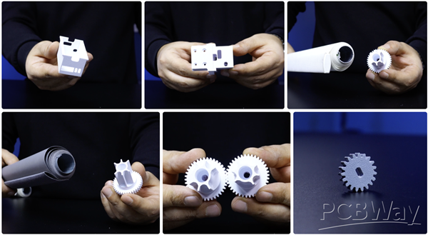
The stepper motor gear attached to the motor shaft was printed with ABS filament to prevent deformation caused by heat and long-term use. All other structural parts were printed using PLA, which is sufficient for mechanical strength and easy to print.
All STL files are shared with the project. PCBWay’s 3D printing service can also be used if you don’t have a printer.
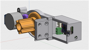
Gear Mechanism Assembly
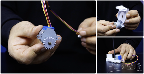
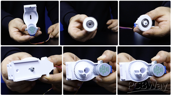
The 3D gear mechanism housing assembly can be completed in just a few steps, as follows:
- Place the stepper motor gear onto the stepper motor shaft. To prevent it from loosening over time, I designed the gear's shaft entry to fit snugly, so you will need to press it on firmly.
- Place the stepper motor and gear into the gear mechanism housing, which is the main component, and secure it with two 4MM bolts.
- Insert the 608ZZ bearing by pressing it firmly into the socket located behind the blind tube gear.
- Place the bearing pin in the center of the bearing. Insert the 3MM bolt through the center of the blind tube gear; the other end of the bolt will come out of the bearing pin.
- Place the blind tube gear into the gear mechanism housing. The center bolt should come out from the back of the gear mechanism housing. Place a nut and bolt of the appropriate size, then tighten the bolt using a screwdriver. You can now move the blind tube gear back and forth along the gear mechanism housing.
The 3D gear mechanism housing assembly is complete. Let's prepare the circuit board before attaching the circuit enclosure.
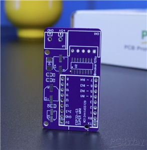
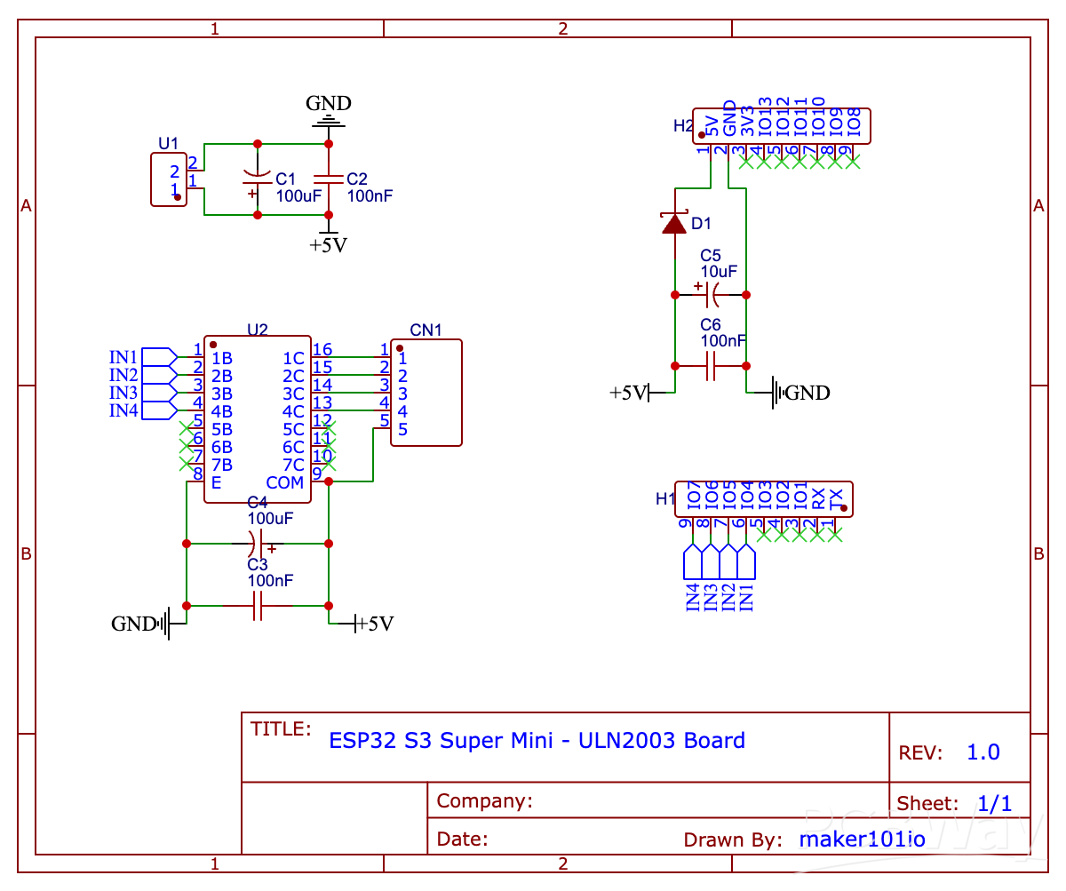
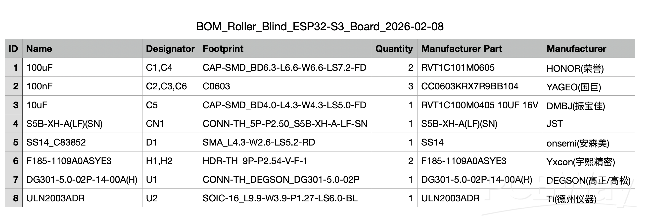
Printed Circuit Board
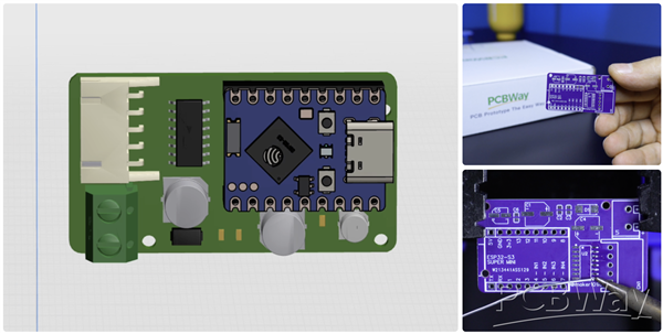
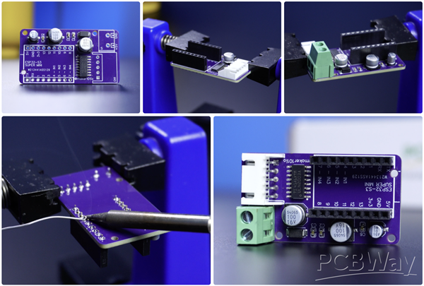
The PCB has been redesigned to be as compact as possible and fits neatly into the integrated enclosure. It now uses an ESP32 board and offers both Wi-Fi and Bluetooth connectivity options.
As always, I chose PCBWay, opened the PCB order page, uploaded the Gerber file, and completed an order for five PCBs for just $5. PCBWay also offers PCB assembly and 3D printing services, so if you're looking for more professional assembly or high-quality 3D prints, this could be a great option.
At this stage, we can move on to soldering the components. Below, you can find a link to the project page containing the full component list and detailed information. To make SMT assembly easier, you can order a stencil along with the PCB and use it to apply solder paste. Alternatively, you can carefully tin the pads using a soldering iron, place the components, and then reflow them in an oven.
Programming
The full source code is attached. In short, the firmware uses the Blynk Cloud infrastructure and WiFi has been chosen as the communication method. The application's usage and features will be discussed in the next step. If you are using ESP32 S3 for the first time, here are the steps to follow for the initial setup:
Arduino IDE – ESP32-S3 Initial Setup
Before uploading any code, the Arduino IDE must be configured for ESP32-S3.
- Open Arduino IDE
- Go to File → Preferences
- Add the ESP32 board manager URL
https://espressif.github.io/arduino-esp32/package_esp32_index.json
- Open Tools → Board → Boards Manager
- Search for ESP32 and install the official Espressif package
- Select:
Board: ESP32S3 Dev Module USB CDC On Boot: Enabled Flash Mode: QIO Partition Scheme: Default
These settings are critical for stable serial output and WiFi behavior on ESP32-S3.
Libraries Used in This Project
The firmware uses the following libraries:
- WiFi – WiFi connection
- BlynkSimpleEsp32 – Blynk Cloud communication
- Preferences – Non-volatile storage (NVS)
All libraries are installed via Arduino Library Manager.
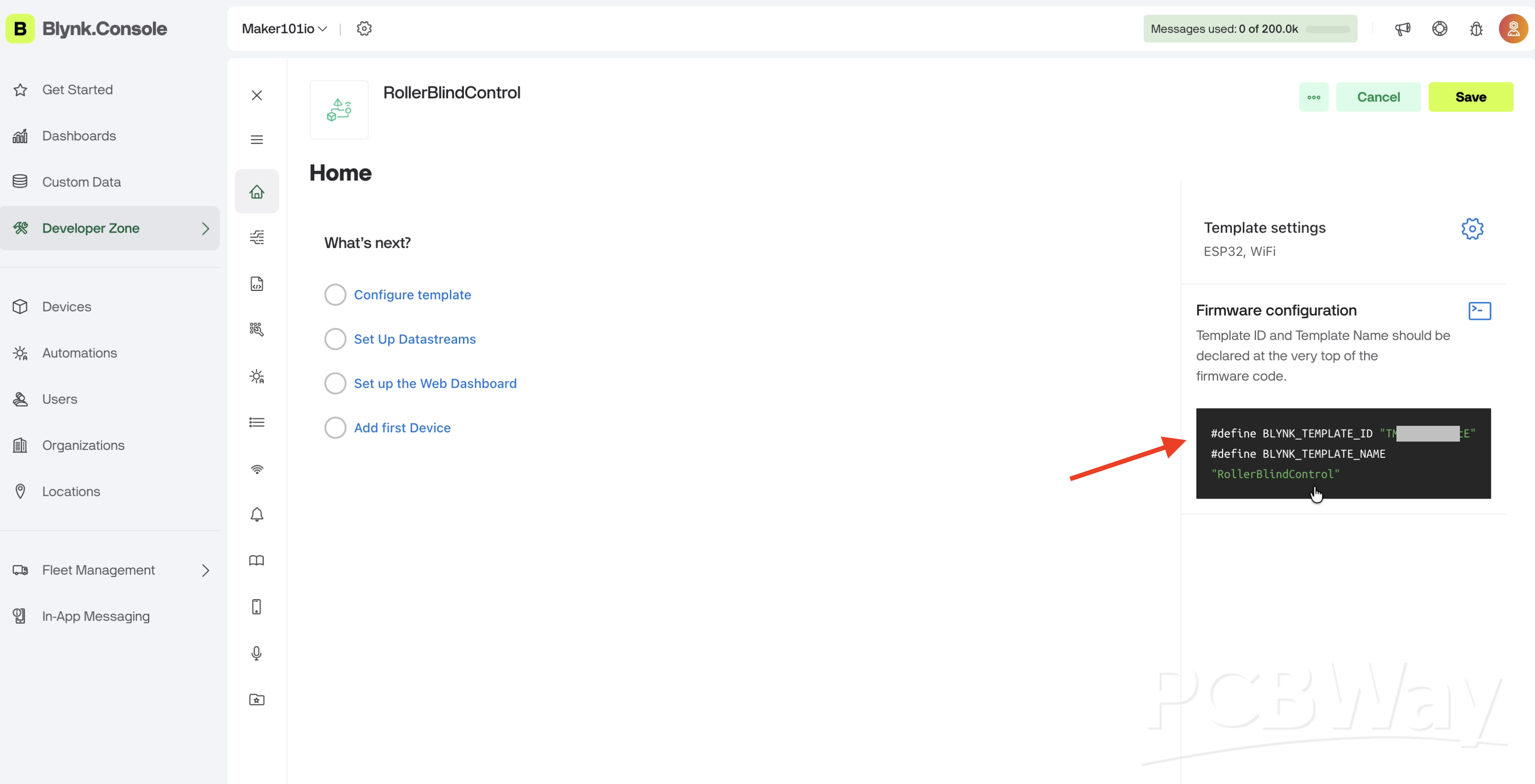
Blynk Cloud Setup
Creating the Blynk Template
- Log in to Blynk Cloud
- Create a New Template
- Select:
- Hardware: ESP32
- Connection type: WiFi
Save the Template ID and Auth Token, these will be added to the code later.
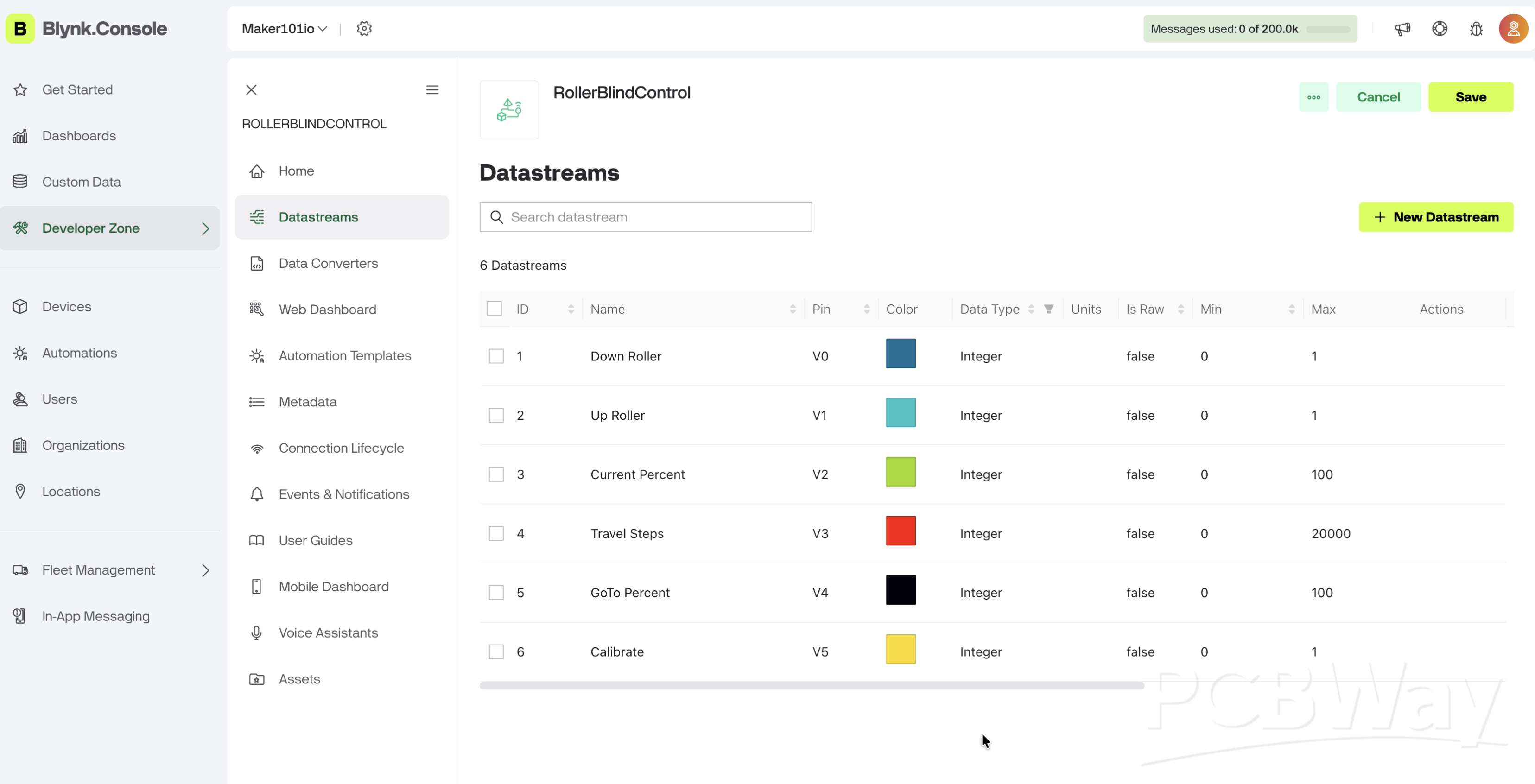
Datastream Configuration
Within the template, go to Data Streams and create the Virtual Pins shown in the image.
All pins are of type Integer, and their maximum values can be increased based on your Travel Steps status. A value of 20,000 was defined for testing, but it was updated to 100,000 for actual use.
Uploading the Code
Before uploading:
- Enter your WiFi SSID and password
- Paste Blynk Template ID and Auth Token
- Select the correct COM port
After upload:
- Open Serial Monitor
- Baud rate: 115200
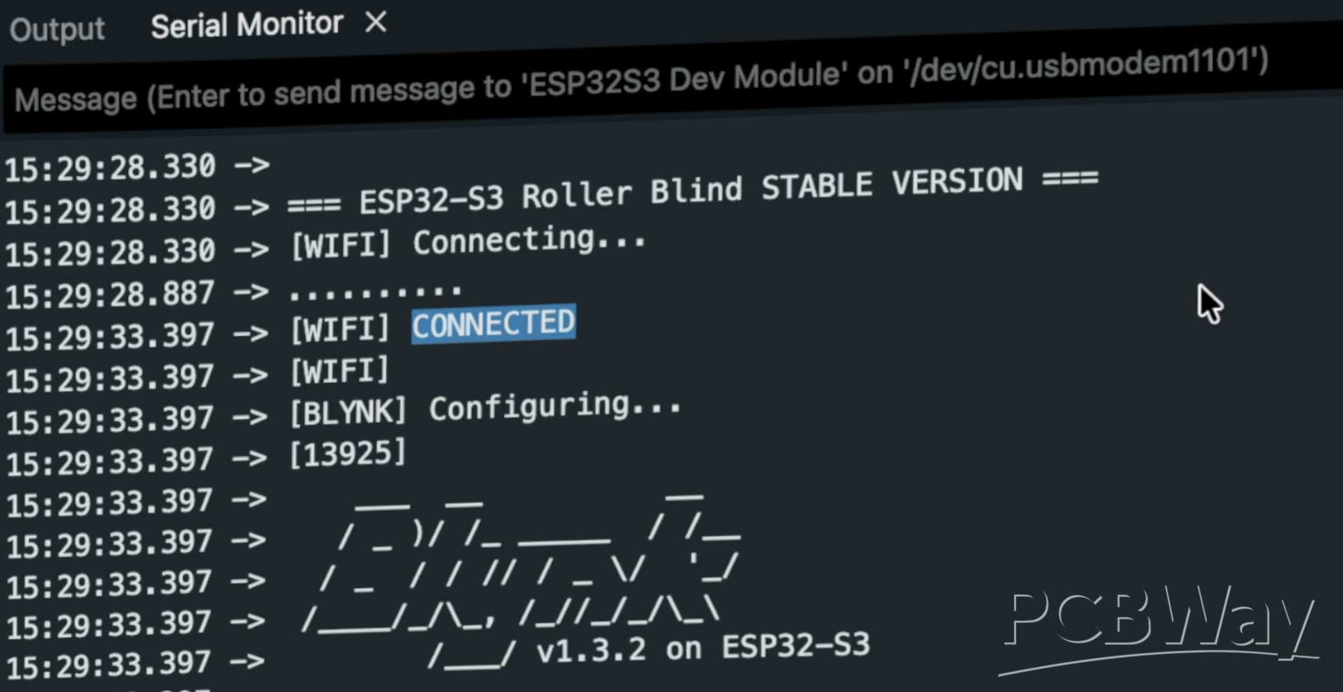
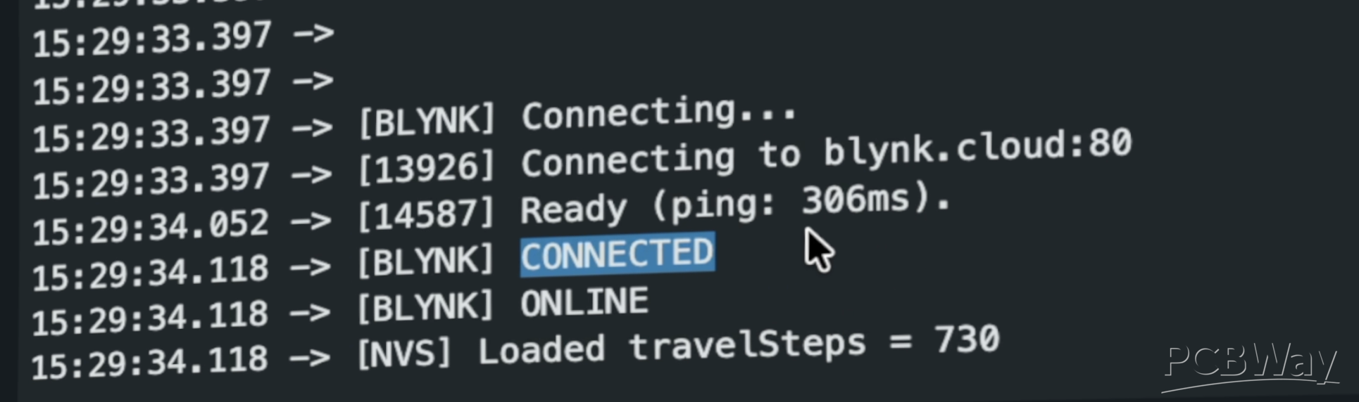
What You Should See in Serial Monitor
If everything is correct, you should see:
[WIFI] CONNECTED [BLYNK] CONNECTED
A Small Modification
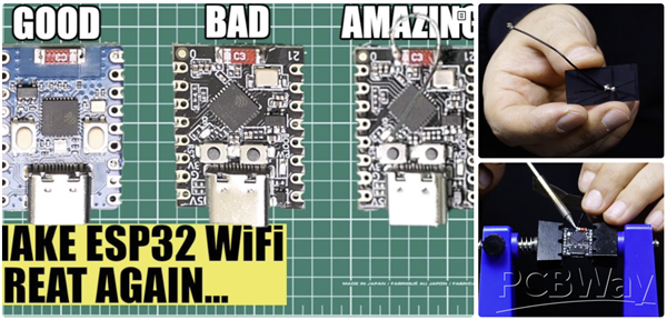
Some ESP32-S3 Mini boards have relatively weak built-in antennas. Since this project uses an enclosure, the WiFi signal strength may be further reduced. To solve this problem, a short wire or external antenna must be added to the antenna pad. For more details, I recommend checking out this informative blog post: https://circuithelper.com/making-the-esp32-c3s-wifi-great-again/
To prevent this, I used a spare adhesive antenna left over from an old WiFi development board. I cut the antenna tip and soldered it directly to one side of the WiFi antenna pad. It doesn't necessarily require an adhesive WiFi antenna; soldering a short piece of copper wire can significantly increase the signal strength.
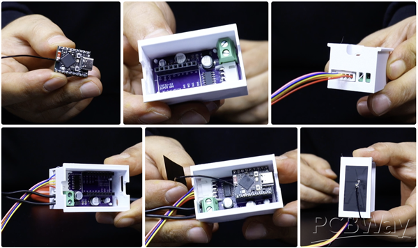
Place the PCB into the circuit enclosure. After connecting the stepper motor connector, connect the 5-volt power supply to the circuit. Next, plug the ESP32-S3 Mini into the PCB and route the antenna cable end outside the enclosure, which will significantly boost signal strength.
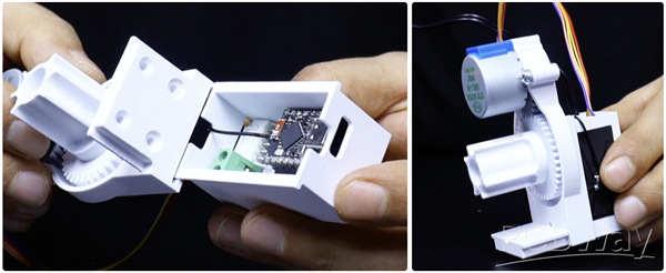
Finally, slide the circuit enclosure behind the 3D gear mechanism. Now we're ready for the next step!
Attach the Motor Gear Mechanism and Mobile App Setup
In this step, attach the 3D Roller Blind Motor gear mechanism to the roller blind and, if desired, complete the mobile app setup. I remove the original mounting parts from the blind profile and tube, then attach the special 3D motor gear set.
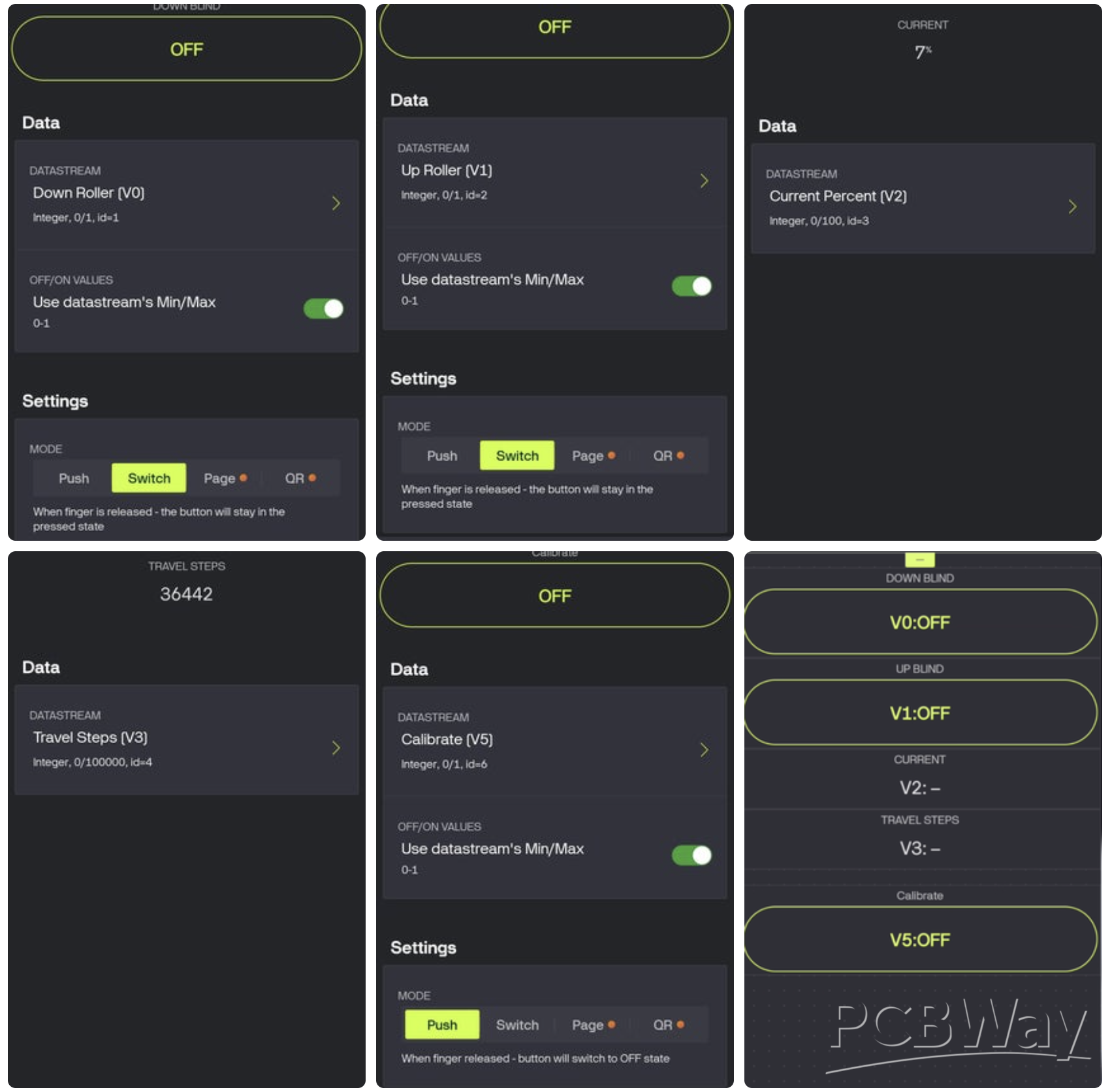
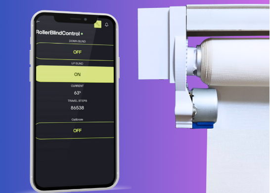
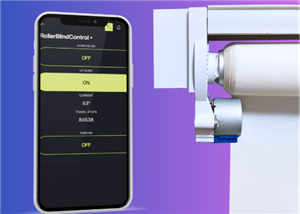
The Blynk Cloud web interface can be used to control the motorized roller blind, but I used the mobile app for better usability. You can download the app from app stores. Then log in with your email account registered with Blynk Cloud. The Templates you created in the web interface will appear on the screen; click on the template to be used. Add the tools to be used in the Template to the screen. These are:
- two Switch Buttons for Down and Up Blind control,
- one Labeled Value for Current data,
- one more Labeled Value for Travel Steps data,
- and finally a Push Button for Calibrate
The required values should be the same as the values you entered in the web interface. You can also see the required values for each tool in the images added.
If your mobile app is ready, it's time for the real test!
Real-world Test
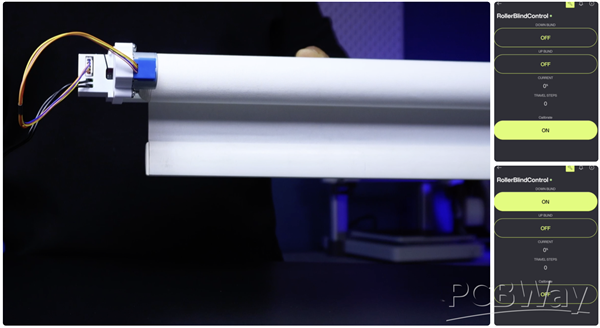
Now let's test the application. First, move the roller blind to its starting position.
- Then press the Calibrate button once. This resets the current position and sets it to zero.
- Next, activate the Blind Down button. The motor gear will start moving and the blind will begin to descend. Wait until the blind reaches the desired position.
- When the blind reaches the desired position, press the Blind Down button again to stop the movement.
As you can see on the application screen, the number of steps is now stored in memory.
- From this point on, when you press the Blind Up button, the blind will automatically return to its starting position and move by a percentage based on the stored number of steps.
- When you activate the Blind Down button again, the blind will move back towards the final position and stop precisely at the calibrated point.
If you want to reset the start and end positions, press the Calibrate button again and repeat the process.
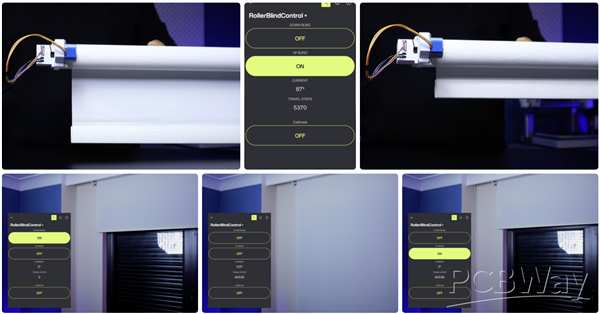
The application and motor gear operate very reliably during short movement tests. Now, let's see how the system performs over a longer movement distance. To do this, I mounted the roller blind in front of a window and began the real-world test.
- First, I moved the blind to its starting position. While the blind was in this position, I pressed the Calibrate button once.
- Then, using the Down button, I activated the motor gear and allowed the blind to move to its fully open position, completely covering the window.
At this point, I should mention that the video is sped up five times. Since a hobby motor was used in this project, it took about three minutes for the blind to reach its final position.
- When the blind reached the desired open position, I released the Blind Down button. As a result, the total number of steps was recorded and displayed in the application.
- Now, by activating the Blind Up button, the blind automatically closes according to the recorded percentage and allows the window to open again. As you can see, the blind reaches the zero position and stops automatically.
If you want to take it a step further, you can also use the built-in scheduling tool in the app. With this feature, the roller blind can operate completely automatically at predefined times throughout the day.
If you liked this project and want to see more content like this, don't forget to follow and like. Thank you for reading.
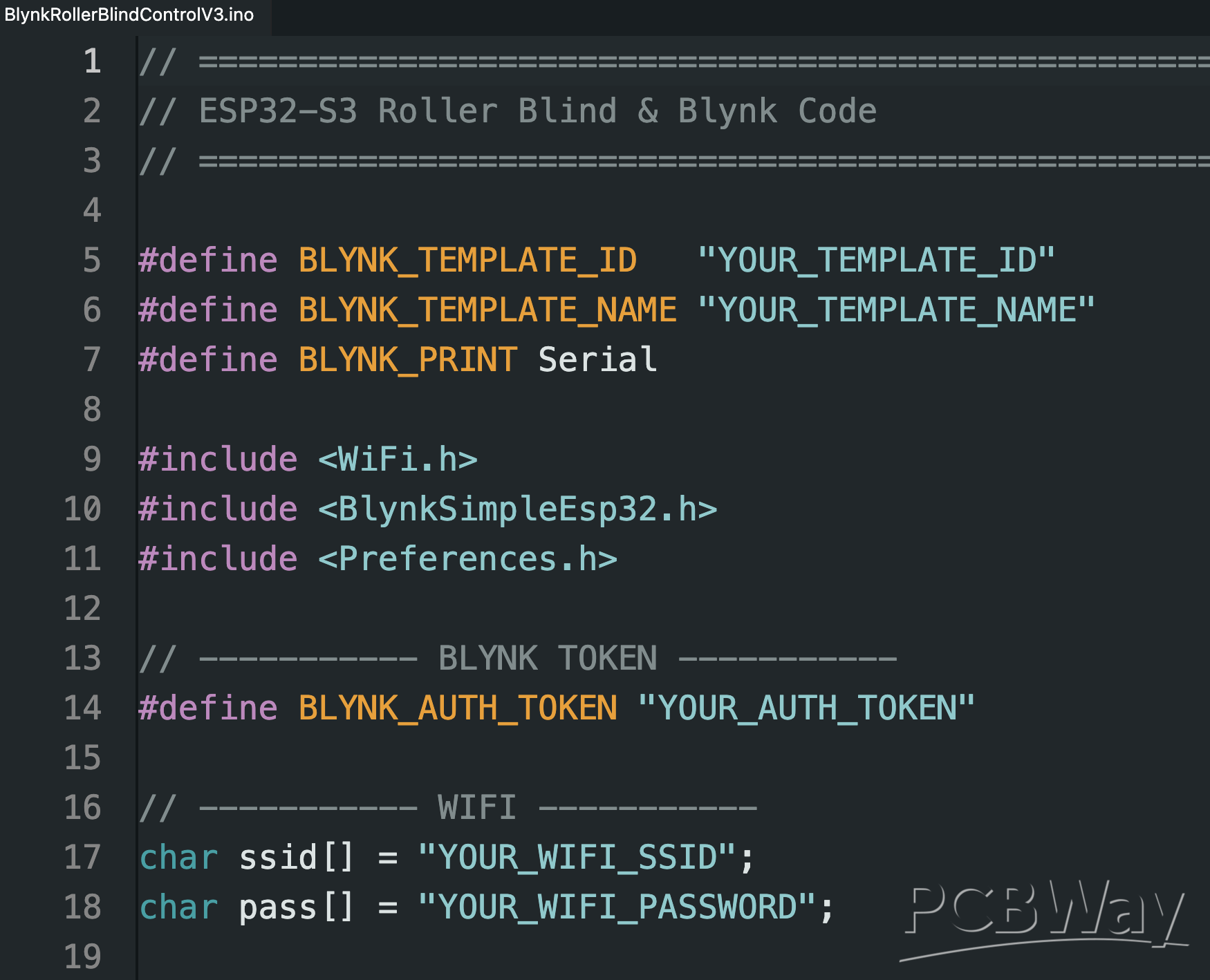
// ======================================================
// ESP32-S3 Roller Blind & Blynk Code
// ======================================================

#define BLYNK_TEMPLATE_ID   "YOUR_TEMPLATE_ID"
#define BLYNK_TEMPLATE_NAME "YOUR_TEMPLATE_NAME"
#define BLYNK_PRINT Serial

#include <WiFi.h>
#include <BlynkSimpleEsp32.h>
#include <Preferences.h>

// ----------- BLYNK TOKEN -----------
#define BLYNK_AUTH_TOKEN "YOUR_AUTH_TOKEN"

// ----------- WIFI -----------
char ssid[] = "YOUR_WIFI_SSID";
char pass[] = "YOUR_WIFI_PASSWORD";

// ----------- MOTOR PINS -----------
#define IN1 4
#define IN2 5
#define IN3 6
#define IN4 7

// ----------- BLYNK PINS -----------
#define VDOWN      V0
#define VUP        V1
#define VCURR_PCT  V2
#define VTRAVEL    V3
#define VGOTO_PCT  V4
#define VCALIB     V5

// ----------- STEPPER DATA -----------
const uint8_t STEP_COUNT = 8;
const uint8_t stepSequence[STEP_COUNT][4] = {
  {1,0,0,1},
  {0,0,0,1},
  {0,0,1,1},
  {0,0,1,0},
  {0,1,1,0},
  {0,1,0,0},
  {1,1,0,0},
  {1,0,0,0}
};

int stepIndex = 0;
bool motorEnabled = false;
int direction = 0;

long currentStep = 0;
long fullTravelSteps = 0;
bool calibrating = false;

// ----------- TIMER & NVS -----------
BlynkTimer timer;
Preferences prefs;

const char* PREF_NAMESPACE = "roller";
const char* KEY_TRAVEL     = "travelSteps";

// ======================================================
// MOTOR HELPERS
// ======================================================
void setCoils(uint8_t a, uint8_t b, uint8_t c, uint8_t d) {
  digitalWrite(IN1, a);
  digitalWrite(IN2, b);
  digitalWrite(IN3, c);
  digitalWrite(IN4, d);
}

void motorStop() {
  motorEnabled = false;
  direction = 0;
  setCoils(0,0,0,0);
  Serial.println("[MOTOR] STOP");
}

void applyStep(int idx) {
  idx = (idx + STEP_COUNT) % STEP_COUNT;
  stepIndex = idx;
  setCoils(
    stepSequence[idx][0],
    stepSequence[idx][1],
    stepSequence[idx][2],
    stepSequence[idx][3]
  );
}

void stepperTick() {
  if (!motorEnabled || direction == 0) return;

  stepIndex += direction;
  applyStep(stepIndex);
  currentStep += direction;

  if (currentStep < 0) {
    currentStep = 0;
    Serial.println("[LIMIT] TOP reached");
    motorStop();
  }

  if (fullTravelSteps > 0 && currentStep > fullTravelSteps) {
    currentStep = fullTravelSteps;
    Serial.println("[LIMIT] BOTTOM reached");
    motorStop();
  }
}

void updatePosition() {
  if (fullTravelSteps <= 0) return;

  int pct = (100L * currentStep) / fullTravelSteps;
  pct = constrain(pct, 0, 100);

  Blynk.virtualWrite(VCURR_PCT, pct);
  Serial.printf("[POS] Step=%ld  %%=%d\n", currentStep, pct);
}

// ======================================================
// WIFI & BLYNK
// ======================================================
void connectWiFi() {
  Serial.println("[WIFI] Connecting...");
  WiFi.mode(WIFI_STA);
  WiFi.begin(ssid, pass);

  unsigned long t0 = millis();
  while (WiFi.status() != WL_CONNECTED) {
    delay(500);
    Serial.print(".");
    if (millis() - t0 > 15000) {
      Serial.println("\n[WIFI] FAILED");
      return;
    }
  }

  Serial.println("\n[WIFI] CONNECTED");
  Serial.print("[WIFI] IP: ");
  Serial.println(WiFi.localIP());
}

BLYNK_CONNECTED() {
  Serial.println("[BLYNK] CONNECTED");
}

BLYNK_DISCONNECTED() {
  Serial.println("[BLYNK] DISCONNECTED");
}

// ======================================================
// NVS
// ======================================================
void loadCalibration() {
  prefs.begin(PREF_NAMESPACE, true);
  fullTravelSteps = prefs.getLong(KEY_TRAVEL, 0);
  prefs.end();

  if (fullTravelSteps > 0) {
    Serial.printf("[NVS] Loaded travelSteps = %ld\n", fullTravelSteps);
    Blynk.virtualWrite(VTRAVEL, fullTravelSteps);
  } else {
    Serial.println("[NVS] No calibration data");
  }
}

void saveCalibration() {
  prefs.begin(PREF_NAMESPACE, false);
  prefs.putLong(KEY_TRAVEL, fullTravelSteps);
  prefs.end();

  Serial.printf("[NVS] Saved travelSteps = %ld\n", fullTravelSteps);
  Blynk.virtualWrite(VTRAVEL, fullTravelSteps);
}

// ======================================================
// BLYNK CALLBACKS
// ======================================================
BLYNK_WRITE(VDOWN) {
  int v = param.asInt();
  Serial.printf("[BLYNK] V0 DOWN = %d\n", v);

  if (v) {
    direction = +1;
    motorEnabled = true;
    Blynk.virtualWrite(VUP, 0);
    Serial.println("[MOTOR] DOWN");
  } else {
    motorStop();
    if (calibrating && fullTravelSteps == 0 && currentStep > 0) {
      fullTravelSteps = currentStep;
      calibrating = false;
      saveCalibration();
      Serial.println("[CAL] FINISHED");
    }
  }
}

BLYNK_WRITE(VUP) {
  int v = param.asInt();
  Serial.printf("[BLYNK] V1 UP = %d\n", v);

  if (v) {
    direction = -1;
    motorEnabled = true;
    Blynk.virtualWrite(VDOWN, 0);
    Serial.println("[MOTOR] UP");
  } else {
    motorStop();
  }
}

BLYNK_WRITE(VCALIB) {
  int v = param.asInt();
  if (v) {
    Serial.println("[CAL] STARTED");
    motorStop();
    currentStep = 0;
    fullTravelSteps = 0;
    calibrating = true;
    Blynk.virtualWrite(VCURR_PCT, 0);
    Blynk.virtualWrite(VTRAVEL, 0);
  }
}

BLYNK_WRITE(VGOTO_PCT) {
  int pct = param.asInt();
  Serial.printf("[BLYNK] GOTO %% = %d (not active yet)\n", pct);
}

// ======================================================
// SETUP / LOOP
// ======================================================
void setup() {
  Serial.begin(115200);
  delay(200);

  Serial.println("\n=== ESP32-S3 Roller Blind FULL DEBUG ===");

  pinMode(IN1, OUTPUT);
  pinMode(IN2, OUTPUT);
  pinMode(IN3, OUTPUT);
  pinMode(IN4, OUTPUT);
  motorStop();

  connectWiFi();

  Serial.println("[BLYNK] Configuring...");
  Blynk.config(BLYNK_AUTH_TOKEN);

  Serial.println("[BLYNK] Connecting...");
  if (Blynk.connect(10000)) {
    Serial.println("[BLYNK] ONLINE");
  } else {
    Serial.println("[BLYNK] FAILED");
  }

  loadCalibration();

  //
  timer.setInterval(3L, stepperTick);        // Motor
  timer.setInterval(200L, updatePosition);   // UI
}

void loop() {
  if (Blynk.connected()) {
    Blynk.run();
  }
  timer.run();
}
DIY Motorized Roller Blind with ESP32-S3 | WiFi Control, 3D Printed Gear & Blynk Cloud
*PCBWay community is a sharing platform. We are not responsible for any design issues and parameter issues (board thickness, surface finish, etc.) you choose.


Raspberry Pi 5 7 Inch Touch Screen IPS 1024x600 HD LCD HDMI-compatible Display for RPI 4B 3B+ OPI 5 AIDA64 PC Secondary Screen(Without Speaker)
BUY NOW


- Comments(3)
- Likes(4)
- 2 USER VOTES
- YOUR VOTE 0.00 0.00
-
10design
-
8usability
-
10creativity
-
10content

-
9design
-
9usability
-
9creativity
-
9content
More by MERT KILIC
-
 3D Printed Theo Jansen Style Octopod Robot (Arduino Based)
Hi everyone! In this project, I will show you an amazing eight-legged robot in the Octopod style! It...
3D Printed Theo Jansen Style Octopod Robot (Arduino Based)
Hi everyone! In this project, I will show you an amazing eight-legged robot in the Octopod style! It...
-
 Creative Modular LED Lighting with Magnetic Pogo Pins & Wi-Fi Control
Hi everyone! Welcome to my latest project: a modular, plug-in LED lighting system that is as fun as ...
Creative Modular LED Lighting with Magnetic Pogo Pins & Wi-Fi Control
Hi everyone! Welcome to my latest project: a modular, plug-in LED lighting system that is as fun as ...
-
 Build a simple 3D printed CNC plotter machine
Hi friends, do you remember this Mini CNC Plotter machine that uses hobby stepper motors and a few 3...
Build a simple 3D printed CNC plotter machine
Hi friends, do you remember this Mini CNC Plotter machine that uses hobby stepper motors and a few 3...
-
 Circuit Activity Board - Educational Electronics
Circuit Activity Board – A Hands-On Project to Learn Basic ElectronicsIn this project, we're going t...
Circuit Activity Board - Educational Electronics
Circuit Activity Board – A Hands-On Project to Learn Basic ElectronicsIn this project, we're going t...
-
 Build a Simple 3D Wall Lighting
Hi friends, this project shows how to make and control 3D hexagonal LED lighting panels. The project...
Build a Simple 3D Wall Lighting
Hi friends, this project shows how to make and control 3D hexagonal LED lighting panels. The project...
-
 Robot Sumo Board
Robot-sumo, or pepe-sumo, is a sport in which two robots attempt to push each other out of a circle ...
Robot Sumo Board
Robot-sumo, or pepe-sumo, is a sport in which two robots attempt to push each other out of a circle ...
-
 ESP32 Mecanum Wheels Robot and Bluetooth Gamepad Controller
In this project we will see how to make an ESP32 Mecanum Wheels Robot which is capable of moving in ...
ESP32 Mecanum Wheels Robot and Bluetooth Gamepad Controller
In this project we will see how to make an ESP32 Mecanum Wheels Robot which is capable of moving in ...
-
 DIY Motorized WiFi Roller Blind - ESP8266 & Blynk
In this project we will see how to control a roller blind via a smartphone application. The reason w...
DIY Motorized WiFi Roller Blind - ESP8266 & Blynk
In this project we will see how to control a roller blind via a smartphone application. The reason w...
-
 Pet Feeder Controlled Via WiFi - ESP8266
How It Works?As you can see, a 3D design was used for the pet feeder. ESP8266-based Wemos D1 Mini bo...
Pet Feeder Controlled Via WiFi - ESP8266
How It Works?As you can see, a 3D design was used for the pet feeder. ESP8266-based Wemos D1 Mini bo...
-
 ESP8266 Two Wheel Robot (NodeMCU and Stepper Motor)
Generally, robot cars are built on a chassis with 2 DC motor wheels and a bovine wheel. While surfin...
ESP8266 Two Wheel Robot (NodeMCU and Stepper Motor)
Generally, robot cars are built on a chassis with 2 DC motor wheels and a bovine wheel. While surfin...
-
 3D Printed Rotating Table Board with Arduino Nano and 28BYJ-48 Stepper Motor
This project shows how to make a 3D printed Rotating Table using Arduino and a hobby stepper motor. ...
3D Printed Rotating Table Board with Arduino Nano and 28BYJ-48 Stepper Motor
This project shows how to make a 3D printed Rotating Table using Arduino and a hobby stepper motor. ...
-
 Hand Gesture Controller for Robotic
The hand gesture controller makes it possible to control applicat...
Hand Gesture Controller for Robotic
Hand Gesture Controller for RoboticThe hand gesture controller makes it possible to control applicat...
-
 How To Make DIY Remote Control Hoverboat at Home
In this video, I showed you how to make your own hoverboat from materials available at home and chea...
How To Make DIY Remote Control Hoverboat at Home
In this video, I showed you how to make your own hoverboat from materials available at home and chea...
-
 How to Make DIY Arduino Gesture Control Robot at Home
Parts Required for Receiver (Tank):1) Robot Tank Chassis - https://bit.ly/3j8y2Q52) Arduino Nano V3 ...
How to Make DIY Arduino Gesture Control Robot at Home
Parts Required for Receiver (Tank):1) Robot Tank Chassis - https://bit.ly/3j8y2Q52) Arduino Nano V3 ...
-
 DIY Circuit Activty Board with Paperclips | MAKER | STEM
You can be creative and design your own circuit and add different sensors (other LEDs...). The idea ...
DIY Circuit Activty Board with Paperclips | MAKER | STEM
You can be creative and design your own circuit and add different sensors (other LEDs...). The idea ...
-
 ATtiny85 Wearable Activity Tracking Watch
How to make the wearable activity tracking watch? This is a wearable gadget designed to vibrate when...
ATtiny85 Wearable Activity Tracking Watch
How to make the wearable activity tracking watch? This is a wearable gadget designed to vibrate when...
-
 DIY Motorized Roller Blind with ESP32-S3 | WiFi Control, 3D Printed Gear & Blynk Cloud
This project is an updated version of my previous Motorized Roller Blind, which reached nearly 300,0...
DIY Motorized Roller Blind with ESP32-S3 | WiFi Control, 3D Printed Gear & Blynk Cloud
This project is an updated version of my previous Motorized Roller Blind, which reached nearly 300,0...
-
 How to Build a Motorized 3D Scanning Turntable for Your Phone
In this project, I’ll show you how to make a simple motorized turntable for 3D scanning. It has thre...
How to Build a Motorized 3D Scanning Turntable for Your Phone
In this project, I’ll show you how to make a simple motorized turntable for 3D scanning. It has thre...
-
-
ARPS-2 – Arduino-Compatible Robot Project Shield for Arduino UNO
1299 0 4 -
A Compact Charging Breakout Board For Waveshare ESP32-C3
1815 3 7 -
AI-driven LoRa & LLM-enabled Kiosk & Food Delivery System
1805 2 0 -
-
-
-
ESP32-C3 BLE Keyboard - Battery Powered with USB-C Charging
1981 0 1 -


