


|
KiCADKicad
|
|

|
fusion360 |
|

|
arduino IDEArduino
|
Electronic Dice with BLE Connectivity
Many of us fondly remember the joy of playing board games like Snakes and Ladders or Ludo during our childhood. These simple yet engaging games brought families and friends together, making any gathering lively and entertaining. Rolling dice, moving tokens, and experiencing the ups and downs of the game taught us lessons in patience and unpredictability while sparking countless laughs and friendly competition. Those moments of flipping game boards in frustration or celebrating a lucky roll remain etched in our memories.
And as you may noticed nowadays many of us are addicted to modern games and may even forget these fun and entertaining board games. The thought of adding a modern twist to the classic games gave me the idea of creating a digital dice with some wireless connectivity. With some tinkering, I decided to opt for the BLE for the connectivity, because the low-power nature of it is really beneficial for such a project.
I decided to go with an ultra-low power microcontroller such as an NRF52840 since these are not only highly power efficient than the counterparts such as ESP32, but they also have superior support for development IDEs such as Arduino IDE. I chose the NINA-B306 module featuring the NRF52840 since it would be much easier to handle and we don’t need to worry about the antenna design headaches compared to using the bare nRF52840 chips. Combining BluetoothLE connectivity, advanced motion sensors, and LED-based visual feedback, the Smart LED Dice bridges the gap between nostalgic gaming and modern tech.
This project was made possible, thanks to our sponsors ALLPCB. The PCB boards used in this project were fabricated by allpcb, more info on how to order will be shared later in this article.
Features of our Smart Electronic Dice
- Based on low power nRF52840 low power, multi-protocol Bluetooth 5 SoC.
- Bluetooth V5 Low Energy connectivity. Pair with smartphones, tablets, or custom BLE-enabled devices.
- Arduino Nano 33 BLE compatible.
- MPU6050 IMU with Integrated accelerometer and gyroscope to detect dice orientation and movement for roll detection.
- TP4056 Lithium-ion battery charging IC with overcharge protection.
- Onboard USB type C port for charging and Programming.
- LEDs for Face Indication.
- RGB LED for status indications.
- Custom PCB with a compact and optimized layout integrates all components.
- Designed to fit within a dice form factor.
- Real-time orientation detection using MPU6050 to determine the face of the dice after rolling.
- LEDs light up to show the upward-facing number on the dice after a roll.
- Android App support. Companion app to receive dice roll data and display results.
Components Required to Build the Smart LED Dice
The components required to build a BLE are listed below. The exact value of each component can be found in the schematics or the BOM.
- NINA-B306-00B module
- MPU6050 IMU
- MIC5219-3.3 LDO
- TP4056 Li-ion battery
- 1615 CA RGB LED
- 0805 LEDs
- SMD resistors and capacitors
- Connectors
- Custom PCB
- 3D printed parts.
- Other tools and consumables.
Smart LED Dice Schematic Diagram
The complete circuit diagram for the Smart LED Dice is shown below. It can also be downloaded in PDF format from the link given at the end.
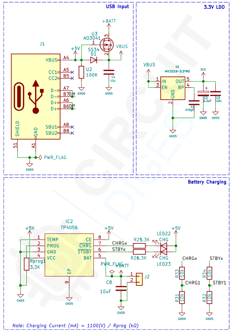
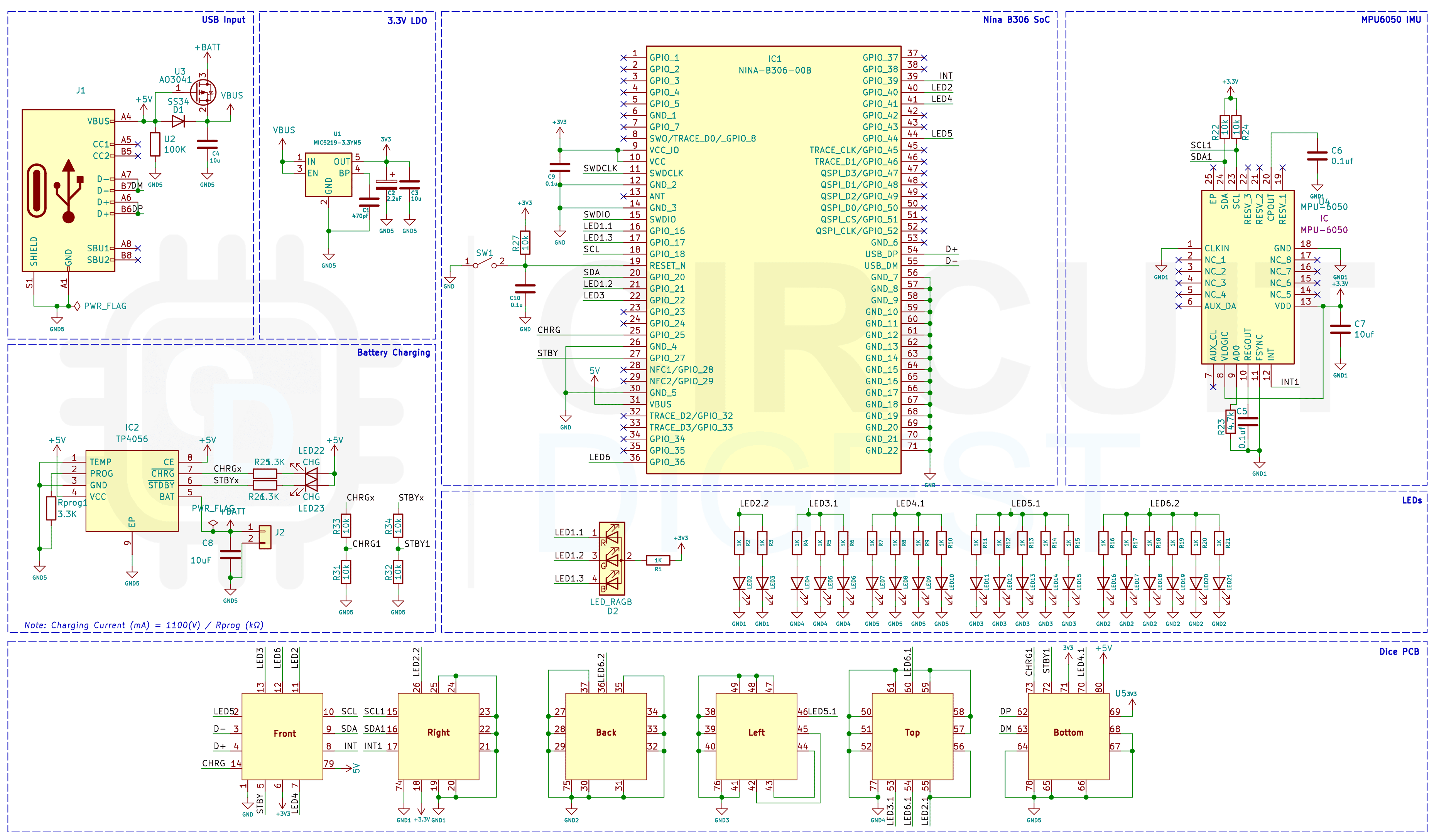 Let’s discuss the Schematics section by section for better understanding. First, we have the power section, which includes the power input, battery charging and voltage regulation. A type C USB port is used for both charging as well as for programming purposes. The power from the USB port is connected to a power path controller circuit built around a P-Channel MOSFET U3 and a diode D1. This will allow us to power the board either from the USB input or from the battery without causing any issues. The battery charging circuit is built around the infamous TP4056 standalone linear Li-lon battery charge controller IC. It will take the 5V input from the USB port and will charge the internal battery. The TP4056 also provides two indicators, one for charging indication and one for full charge indication.
We have also connected voltage dividers to these indicator pins which can be used for monitoring the charging status. For converting the VBUS voltage from the power path controller to 3.3V we have used an MIC5219 ultra-low noise low drop out voltage regulator. With very minimal auxiliary components the MIC5219 provides a very stable output voltage even when the battery charge level is low.
Next, we have the Nina B306-00B module as the brain. The Nina B306-00B features the Nordic Semiconductor nRF52840 Bluetooth 5 Low Energy SoC, featuring an Arm Cortex-M4 processor with a floating-point unit, operating at 64 MHz. It integrates 1 MB of flash memory and 256 kB of RAM, offering ample space for code and data storage. For motion and orientation detection, we have used an MPU6050 IMU from InvenSense, which features a 3-axis gyroscope and a 3-axis accelerometer on the same silicon die, together with an onboard Digital Motion Processor that processes complex 6-axis MotionFusion algorithms. The MPU6050 is interfaced with the Nina B306 module via the I2C interface.
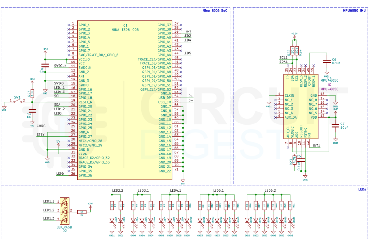
For indicating the Dice faces we have used LEDs. Each face will have a corresponding number of LEDs. Apart from the face with one LED, on all other faces, we are using 0805 LEDs connected in parallel with separate current limit resistors. For the face with one LED, we have used an RGB LED. This RGB is not only used for the face indication but also for indicating connectivity status. The RGB led with 1615 package made it the best choice for this without compromising on the size. It is small enough to fit with the aesthetics and easy to handle while assembling the circuit.
PCB for Smart LED Dice
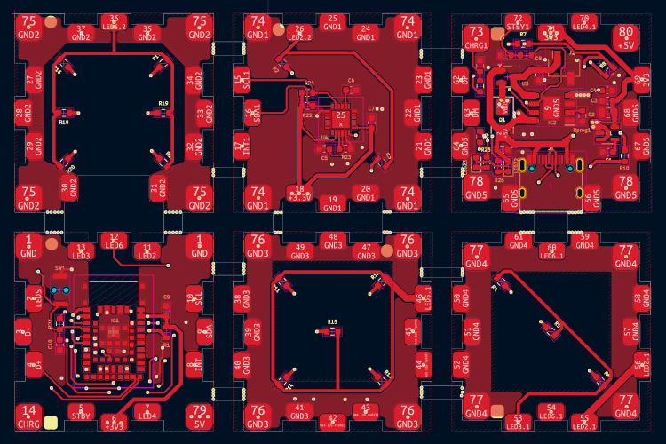
For this project, we have decided to make a custom PCB. This will ensure that the final product is as compact as possible as well as easy to assemble and use. The PCB is designed with KiCad. All the design files are available to download from the GitHub repo linked below this article. The PCB has a dimension of each face is approximately 30mm x 30mm. And in total there are 6 such PCBs. But for manufacturing, we have created a panel with all 6 of them with size of 63x96mm, with stamp holes for easy separation.
Here is the top layer of the PCB.
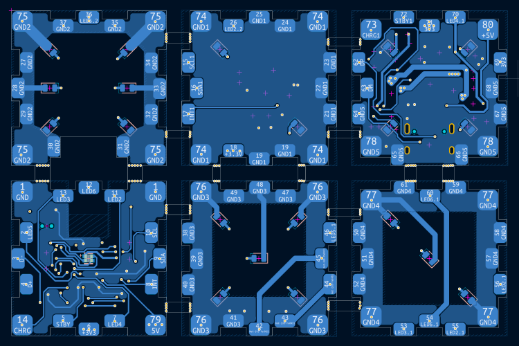
The below image shows the bottom layer of the PCB.
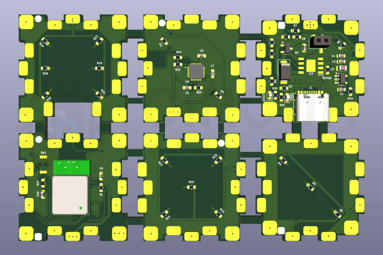
And here is the 3D view of the PCB.
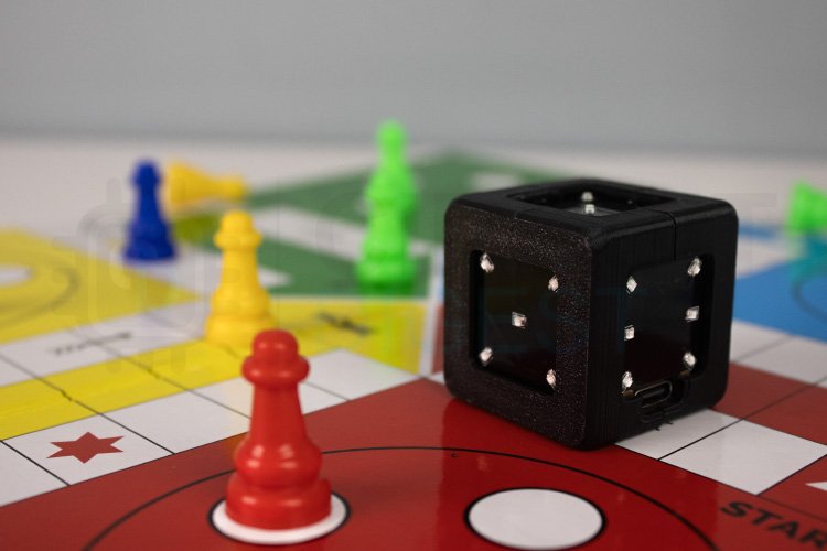
Assembling the Smart LED Dice
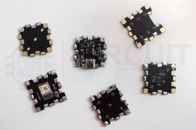
To assemble the SMART LED Dice, first assemble each PCB on the panel. Each PCB represents one face of the dice. One side will have the LEDs and the other side will have all other components. Here is the fully assembled PCB.
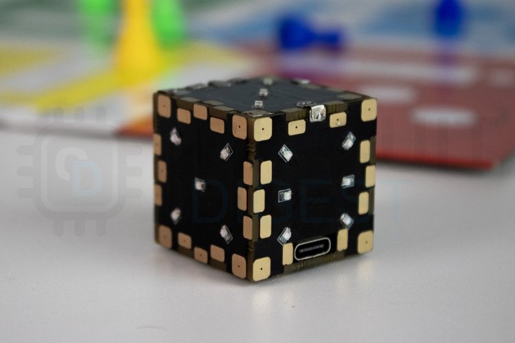
Here is the fully assembled Dice.
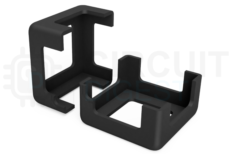
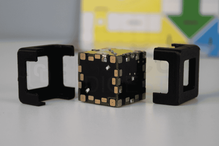
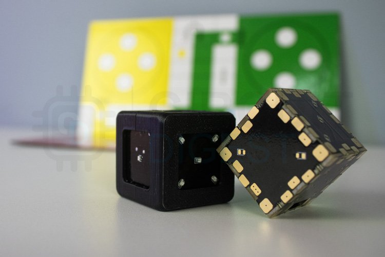
3D Printed Parts
We have designed a 3D-printed cover enclosure that will fit over the PCB. These parts will ensure that the sharp edge of the PCB dice won’t affect its movements and that it rolls smoothly. The files for all the 3D printed parts can be downloaded from the GitHub link provided at the end of the article along with the Arduino sketch and bitmap file. Learn more about 3D printing and how to get started with it by following the link. You can download the 3D files from Thingiverse or from the project GitHub repo.
Thingyverse : https://www.thingiverse.com/thing:6855807
Here are the 3D-printed parts.
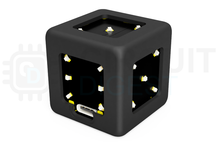
And here is the fully assembled Smart LED Dice with the 3D enclosure.
How Does the Smart LED Dice Work?
When powered on, the dice enters a standby mode, awaiting a BLE connection. During this time, the integrated RGB LED flashes red, green, and blue in a loop to indicate it is ready to connect. Once a BLE device, such as a smartphone or similar, successfully connects, the RGB LED turns off, signalling the connection and placing the dice in an idle state, ready for user interaction. The dice is equipped with an MPU6050 motion sensor to detect the dice roll. When a motion is detected, all face LEDs illuminate sequentially in a rolling effect, simulating the dice being tossed. This dynamic pattern continues until the dice become stationary. Once stationary, the dice determine the upward-facing face using data from the motion sensor. The LEDs corresponding to the upward-facing face start to flash to indicate the result.
To communicate the result to the connected BLE device, the dice updates two BLE characteristics. The Status Characteristic indicates whether a new roll and valid face detection have occurred. It is set to 1 after a roll is detected and can be reset to 0 by the connected device, allowing the dice to prepare for the next roll. The Face Number Characteristic transmits the number that corresponds to the upward-facing face and remains unchanged until the next roll. Notifications are sent to the connected device whenever these characteristics are updated, prompting it to read the values. Once the connected device reads the face number and resets the status characteristic to 0, the dice become ready to detect the next shake or roll. This ensures a smooth interaction cycle, where the dice locks further roll detection until the connected device confirms it is ready for the next action.
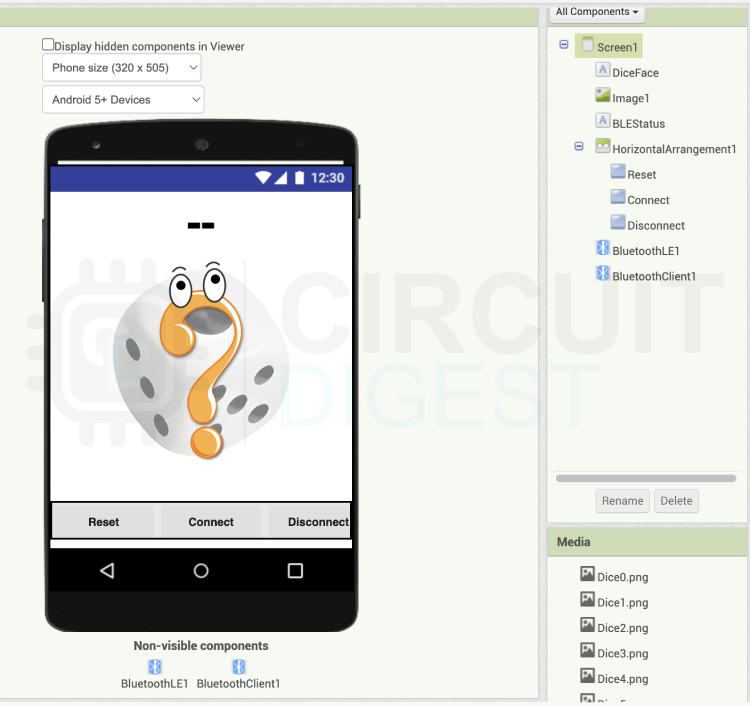
BLE Dice Companion APP
To demonstrate the the functionalities of the Smart LED Dice we have created a simple smartphone app using the MIT App Inventor. The app has only the bare minimum components. There are two labels, one to show the connection status and one to show the result. There is an image element which is used to display the result graphically. We have added three buttons to the UI, of which two are for connecting and disconnecting the BLE connection. The reset button is used for debugging purposes, which will manually reset the status characteristics to zero.
Here is the app's block view.
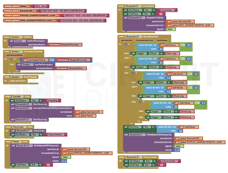
We have created four global variables to store the BLE device name, service UUID, status characteristics UUID and dice face characteristic UUID. As soon as the app is open, it will check if the necessary permissions are already granted or not. If not granted it will prompt to grant those permissions. Make sure you have turned on the Bluetooth and location from the device settings. Once all the permissions are granted all you have to do is click on the connect button. The app will automatically scan and connect to the Smart LED Dice using the device name and service UUID. If you want to disconnect the device you can either click on the disconnect button or close the app.
Once connected to the Smart LED Dice the app will register for notifications for the Dice face characteristics. This way, as soon as the face characteristics value is changed the app will get notified. Once notified the app will read this value and display it on the app screen. It will also display the corresponding image indicating the result. Once the value is read successfully the app will update the status characteristics with the value zero to enable the dice to detect the next roll.
Both the Android app installer file as well as the MIT app inventor project files can be found on the project GitHub repository link provided at the end of this tutorial. While using the MIT app inventor don’t forget to install the BluetoothLE extension if it is not already installed.
To know more about the project check Build Your Own Electronic Dice with Arduino Nano 33 BLE for Digital Board Games
Electronic Dice with BLE Connectivity
Project images are for reference only. Actual production is based on the manufacturing files on the project page.
Please review the designer's notes (e.g., PCB thickness) and select the appropriate options.
PCBWay is not responsible
for issues caused by unsuitable parameter selections.
For more important ordering information, please refer to
Read More


Raspberry Pi 5 7 Inch Touch Screen IPS 1024x600 HD LCD HDMI-compatible Display for RPI 4B 3B+ OPI 5 AIDA64 PC Secondary Screen(Without Speaker)
BUY NOW


- Comments(0)
- Likes(1)
More by Jobit Joseph
-
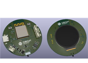
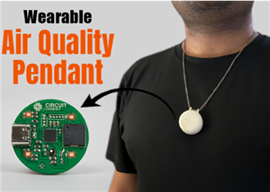 How to build a Wearable Air Quality Monitor Pendant using STM32 & SGP40 Sensor
This DIY Wearable Air Quality Monitor Pendant is a compact, battery-powered device designed to conti...
How to build a Wearable Air Quality Monitor Pendant using STM32 & SGP40 Sensor
This DIY Wearable Air Quality Monitor Pendant is a compact, battery-powered device designed to conti...
-
 Smart Digital Ludo Game Board with Multicolour PCB
Ludo, a beloved childhood game, holds a special place in our hearts with its simple and engaging gam...
Smart Digital Ludo Game Board with Multicolour PCB
Ludo, a beloved childhood game, holds a special place in our hearts with its simple and engaging gam...
-
 Electronic Dice with BLE Connectivity
Many of us fondly remember the joy of playing board games like Snakes and Ladders or Ludo during our...
Electronic Dice with BLE Connectivity
Many of us fondly remember the joy of playing board games like Snakes and Ladders or Ludo during our...
-
 3D printed Enclosure Backplate for Riden RD60xx power supplies
3D printed Enclosure for Riden RD60xx power supplies such as RD6006, RD6012, RD6018, RD6024 and RD60...
3D printed Enclosure Backplate for Riden RD60xx power supplies
3D printed Enclosure for Riden RD60xx power supplies such as RD6006, RD6012, RD6018, RD6024 and RD60...
-
 3D printed Enclosure for Riden RD60xx power supplies
 such as RD6006, RD6012, RD6018, RD6024 and RD60...
3D printed Enclosure for Riden RD60xx power supplies
3D printed Enclosure for Riden RD60xx power supplies such as RD6006, RD6012, RD6018, RD6024 and RD60...
-
 Suzuki Ignis Universal Armrest No Screw Adapter
I own a 2024 Suzuki Ignis. When I searched for an armrest for my car I couldn't find any domesticall...
Suzuki Ignis Universal Armrest No Screw Adapter
I own a 2024 Suzuki Ignis. When I searched for an armrest for my car I couldn't find any domesticall...
-
 Wireless Potentiostat for Electrochemical Analysis
This wireless potentiostat is based on the ADuCM355 SoC from Analog Devices, tailored for portable e...
Wireless Potentiostat for Electrochemical Analysis
This wireless potentiostat is based on the ADuCM355 SoC from Analog Devices, tailored for portable e...
-
 160 Channel Configurable DAC Controller
The DAC controller board features 160 individually controllable 16-bit DAC output. It can output vol...
160 Channel Configurable DAC Controller
The DAC controller board features 160 individually controllable 16-bit DAC output. It can output vol...
-
 ESP32 IoT Water Flow Meter with Real-Time Monitoring
OverviewThis project demonstrates how to build a smart water flow meter using an ESP32 microcontroll...
ESP32 IoT Water Flow Meter with Real-Time Monitoring
OverviewThis project demonstrates how to build a smart water flow meter using an ESP32 microcontroll...
-
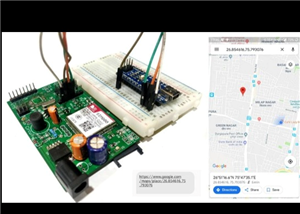 DIY GSM GPS Location Tracker with Arduino
Project OverviewThis project demonstrates how to build a simple and reliable location tracking syste...
DIY GSM GPS Location Tracker with Arduino
Project OverviewThis project demonstrates how to build a simple and reliable location tracking syste...
-
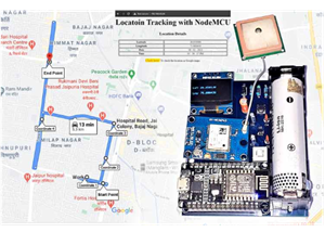 IoT GPS Tracker with NodeMCU and Google Maps
OverviewThis project demonstrates how to build an IoT-based GPS tracking system using a NodeMCU (ESP...
IoT GPS Tracker with NodeMCU and Google Maps
OverviewThis project demonstrates how to build an IoT-based GPS tracking system using a NodeMCU (ESP...
-
 ESP32 Retro Game Console with OLED Display
OverviewThis project demonstrates how to build a compact, handheld retro gaming console using the ES...
ESP32 Retro Game Console with OLED Display
OverviewThis project demonstrates how to build a compact, handheld retro gaming console using the ES...
-
 High Power Boost Converter Using TL494
OverviewThis project demonstrates the design and implementation of a high-power, high-efficiency DC-...
High Power Boost Converter Using TL494
OverviewThis project demonstrates the design and implementation of a high-power, high-efficiency DC-...
-
 DIY ESP32 Oscilloscope Project
OverviewThis project demonstrates how to build a simple and affordable oscilloscope using an ESP32. ...
DIY ESP32 Oscilloscope Project
OverviewThis project demonstrates how to build a simple and affordable oscilloscope using an ESP32. ...
-
 ESP32 Desktop Weather Station
Project OverviewBuild a compact desktop weather station using an ESP32 that measures temperature, hu...
ESP32 Desktop Weather Station
Project OverviewBuild a compact desktop weather station using an ESP32 that measures temperature, hu...
-
 ESP32 Capacitive Touch Home Automation
OverviewMechanical switches wear out over time and can be prone to failure due to dust, moisture, or...
ESP32 Capacitive Touch Home Automation
OverviewMechanical switches wear out over time and can be prone to failure due to dust, moisture, or...
-
 ESP32-Powered Smart Energy Meter for Real-Time Monitoring
ESP32-Powered Smart Energy Meter for Accurate Consumption TrackingIn modern electronics and IoT appl...
ESP32-Powered Smart Energy Meter for Real-Time Monitoring
ESP32-Powered Smart Energy Meter for Accurate Consumption TrackingIn modern electronics and IoT appl...
-
 Build Your Own ESP32 AI Voice Assistant with MCP Integration
Project OverviewThe ESP32 AI Voice Assistant with MCP Integration is an advanced voice-controlled sm...
Build Your Own ESP32 AI Voice Assistant with MCP Integration
Project OverviewThe ESP32 AI Voice Assistant with MCP Integration is an advanced voice-controlled sm...
-
Programmable Mist Maker - XIAO / QT PY Extension
1097 2 1 -
RadioHAT - Raspberry Pi radio development platform
915 0 2 -
-
-
-
-
ARPS-2 – Arduino-Compatible Robot Project Shield for Arduino UNO
3345 0 6 -
A Compact Charging Breakout Board For Waveshare ESP32-C3
3961 3 8 -
AI-driven LoRa & LLM-enabled Kiosk & Food Delivery System
4347 2 2


