|
|
ESP32-WROOM-32 |
x 1 | |
|
|
720 coreless motor |
x 1 | |
|
|
55mm propellers |
x 1 | |
|
|
MPU-6050 |
x 1 | |
|
|
CP2102N-A02-GQFN28Silicon Labs
|
x 1 | |
|
|
TP4056-42-ESOP8TOPPOWER(南京拓微)
|
x 1 | |
|
|
MIC5219-3.3YM5 |
x 1 |

|
KiCADKicad
|
|
|
|
ESP-IDFEspressif
|
Low Cost Drone using ESP32
Drones have rapidly evolved from niche hobbies to versatile tools with a wide range of applications, from photography to agriculture or even for defence and military purposes. Depending on the application, features, and payload capacity their price will vary from pocket changes to a few million. Even though the basic principle behind these drones may appear simple, there is a lot of technology and computation that goes behind it for proper operations and the desired result from these drones—for example, maintaining stability while in the air requires precision sensors such as a Gyroscope and proper processing of reading taken with it. In this project, we are going to make a drone that can be easily controlled using our phones.
This DIY drone is small in size and can be built using easily available components such as ESP32 modules, MPU6050 IMU, coreless motors, and plastic propellers.
Features of our DIY WiFi-Controlled Drone
- WiFi controlled: This can be controlled using a smartphone.
- MPU6050 IMU for stability control.
- All-in-one PCB: Doesn’t need any 3D printed parts or such.
- Easily upgradable: Additional features such as position hold or height hold can be added using external modules.
- Small size and lightweight.
- Built-in battery charger.
- Built-in USB interface for programming and debugging.
- Android and IOS apps.
- Open source
Components Required to Build the DIY WiFi-Controlled Drone
The components required to build the DIY WiFi Controlled Drone are listed below. The exact value of each component can be found in the schematics or the BOM.
- ESP32 Wroom Module – x1
- CP2102N USB - UART controller – x1
- MPU6050 IMU – x1
- TP4056 Li-ion charger IC – x1
- MIC5219-3.3YM5 3.3v LDO – x1
- AO3401 P - MOSFET – x1
- 2N7002DW dual N - MOSFET – x1
- SI2302 N - MOSFET – x4
- SS34 Diode – x1
- 1N4148 Diode – x4
- SD Card Reader – x1
- Type C USB Connector 16Pin – x1
- LiPo Battery 1300mAh 30C – x1
- 720 Coreless Motor – x4
- 55mm propeller type A(CW) – x2
- 55mm propeller type B(CCW) – x2
- 7mm rubber grommet – x4
- SMD resistors and capacitors
- SMD LEDs
- SDM Slide Switch
- Connectors
- Custom PCB
- Other tools and consumables.
DIY WiFi-Controlled Drone Complete Circuit Diagram
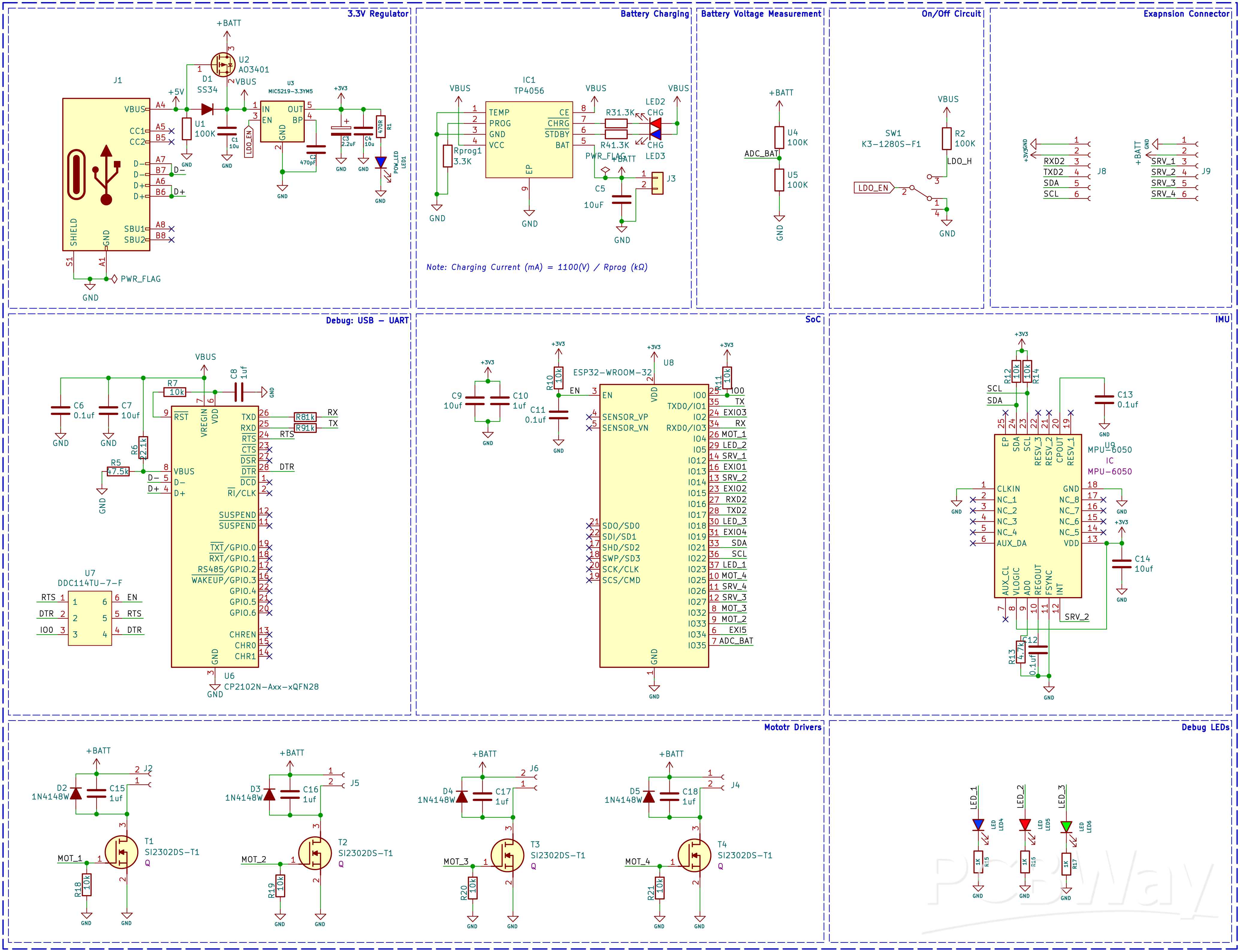
The complete circuit diagram for the DIY WiFi Controlled Drone is shown below. It can also be downloaded in PDF format from the link given at the end.

Let’s discuss the Schematics section by section for better understanding. A type C USB port is used for both charging as well as programming purposes. The power from the USB port is connected to a power path controller circuit built around a P-Channel MOSFET U2 and a diode D1. When the USB power is available the device will operate from the USB power and also will charge the internal battery, when the USB power is cut, the device will automatically change to battery power. For voltage regulation, we have used a MIC5219 3.3V LDO from Microchip, which is capable of providing up to 500mA of current with a very low dropout voltage of 500mV at full load. A slide switch with a pullup resistor is connected to the enable pin of MIC5219. This switch is used for turning on and off the thermal camera. When this pin is pulled to the ground the LDO will be shut down and hence the other parts of the device too, except the battery charging section. For charging the internal battery we are using a TP4056 charge controller which is capable of a maximum charge current of 1A. For battery voltage sensing we have used a classic voltage divider, which will reduce the battery voltage to a safe level for measurement.

In the next section, we have the ESP32 SoC itself along with the programming circuit and the MPU6050 PMU chip. The programming circuit consists of a CP2102 USB to UART controller along with a 2N7002DW dual N – N-Channel MOSFET from ON Semi. We have used the CP2102 with the QFN28 package. The tiny dual MOSFET will act as an auto-reset circuit for the ESP32 thus removing any need for manual rest or boot selection circuitry reducing board size and BOM cost. The circuit around the ESP32 is standard, just bypass capacitors and pullup resistors. The MPU6050 PMU is used for flight stabilization and motion control. It is interfaced with the ESP32 SoC using the standard I2C pins GPIO21 and GPIO22.
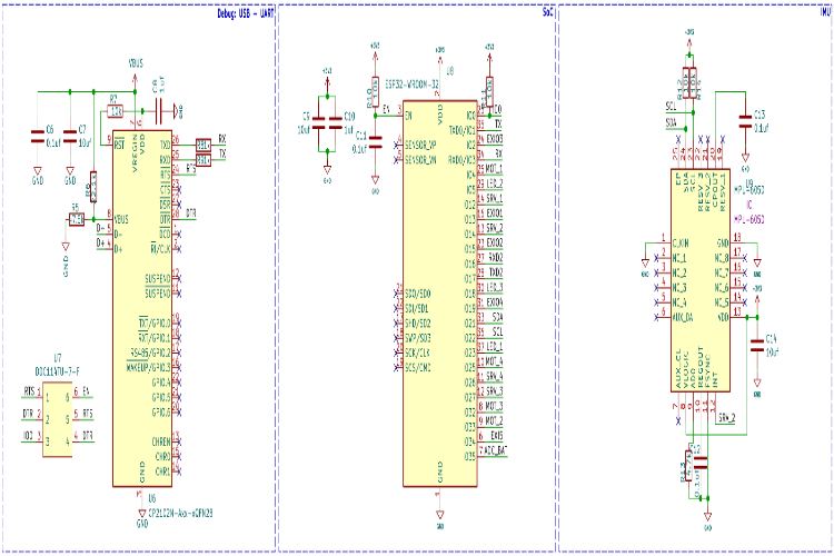
In the last section, we have the motor driver circuit. Each motor driver circuit consists of SI2302 N-Channel MOSFET along with a flyback diode and pulldown resistor. There are 4 such circuits, for each motor. When a high signal is applied to the gate of the driver MOSFET, it will turn on and drive the motor. We will be using PWM signals to control the motor speed. The flyback diode and the capacitors are in place to protect the circuit from any back EMF or voltage spikes.
We have also added three LEDs for debugging purposes apart from the power and charging indicators. The blue LED will blink slowly during sensor calibration and will blink at a fast pace indicating the system is ready for take-off. The green LED will start blinking when a UDP connection is detected from the controller app. The RED LED is used to indicate low battery status, it will lit full-time if the battery voltage is low.

PCB for DIY WiFi-Controlled Drone
For this project, we have decided to make a custom PCB. This will ensure that the final product is as compact as possible as well as easy to assemble and use. We have also designed the PCB in a way that the feet for the drone are also included in the PCB and Can be easily broken away from the main PCB. Here are the top and bottom layers of the PCB.

Here is the PCB.


Here is the 3D render of the fully assembled drone.
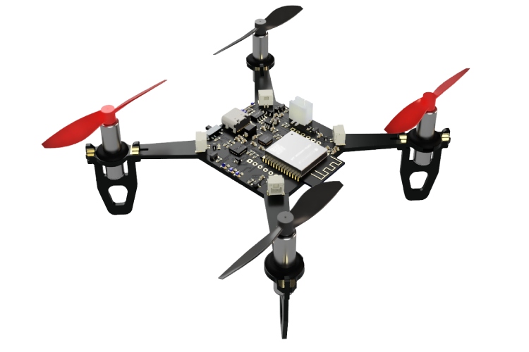
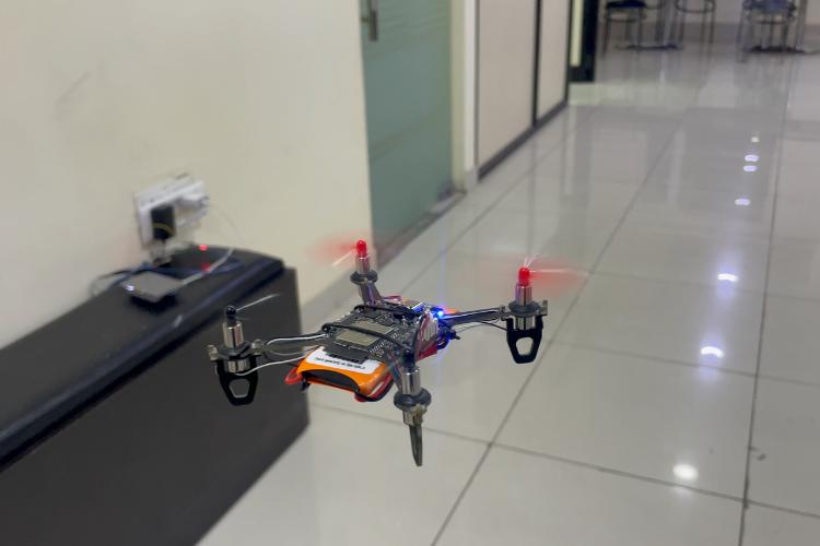
And here is the fully assembled drone.

Propeller Direction
Install A and B propellers according to the figure below. During the power-on self-test, check if the propellers spin properly and are spinning in the correct direction.

Firmware for the DIY WiFi-Controlled Drone
The firmware from our DIY drone is based on the ESP-drone firmware from Espressif. The code is written with ESP-IDF, and the version that is used to compile this code is ESP-IDF 4.4.5. Follow the following link to install and configure ESP32 IDF version 4.4.5. You can either build the firmware from scratch using the source provided at the Github repo below or you can just flash the binary file provided within the same repo if you don’t want the hassle. Make sure to use the source code provided within the below GitHub, because there are many modifications on the Espressif’s code to suit our PCB design.
Flashing the Firmware
To flash the code on our ESP32 Drone, you can follow any one of the below three methods.
Method 1: Building from Source using ESPIDF
To start with install and configure ESP-IDF. Please follow the detailed instructions from Espressif. Make sure to install version 4.4.x of ESP-IDF.
Once the ESP-IDF is installed clone the ESP-Drone firmware repo using git and navigate to the firmware folder.
git clone https://github.com/Circuit-Digest/ESP-Drone.git cd ESP-Drone/Firmware/esp-drone
You can change all the firmware configurations using menuconfig. For our use case, the current configuration is enough, and you don’t need to change anything.
idf.py menuconfig
Now to build and flash the firmware you can use the flash command. It will automatically build and flash the project. Replace PORT with your ESP32-S2 board’s serial port name.
idf.py -p PORT flash
Method 2: Using ESPTOOL
To use the ESPtool, make sure you have installed the ESP IDF. You can find the instructions for that in the previous section. Once installed and configured open the terminal in the same folder as the firmware image and use the following command to flash the firmware.
esptool.py write_flash --flash_size detect 0x0 ESPDrone.bin
Method 3: Using ESP32 Flash Download Tool
First download the ESP32 Flash Download Tool
Extract it to a folder and double-click on the exe file to run it. When prompted select ESP32 in the chip type field and click on OK.
Select the firmware file with the ESPDrone.bin file and add the address as 0x00. Select the proper com port and click on erase. Once the flash erase is complete click on START to flash the firmware
Thats it. You are ready to use your DIY drone.
Using The Drone
Place the drone on a flat surface and turn it on. As soon as it’s turned on the flight controller will create a WiFi Hotspot. Connect to it using the password 12345678 and open the app. For the IOS the app can be downloaded from the App Store, just search for ESP-Drone APP. For Android, you can download the app from the following link. Keep in mind that the app is created and hosted by a third party. So, install them at your own will. The app interface will look like this.
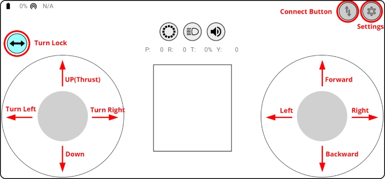
Click on the connect button to start communicating with the drone. When the connection is established successfully between your drone and the APP, the LED on the drone blinks GREEN. The turn lock button can be used to lock the left controller for just up and down or up, down, left turn and right turn. Use the left stick to tack off or land the drone. Use the right stick to control the movements. If the drone disconnects from the app or the drone itself is rebooting when trying to take off, that means the battery can’t provide enough power. We have used a 1300mAh 30C battery. So please ensure to use a battery with a higher discharge rating.
Preflight Check
Place the drone with its head on the front, and its tail (i.e., the antenna part) at the back.
Place the drone on a level surface and power it up when the drone stays still.
After the communication is established, check if the LED at the drone tail blinks GREEN fast.
A blinking RED LED indicates battery LOW, Charge the battery if it happens.
Slide forward the Trust controller slightly to check if the drone can respond to the command.
Use the right controller to check if the direction control works well.
To know more about how to build this low-cost drone please check out Let's Build a Low-Cost Drone using ESP32
Low Cost Drone using ESP32
*PCBWay community is a sharing platform. We are not responsible for any design issues and parameter issues (board thickness, surface finish, etc.) you choose.

Raspberry Pi 5 7 Inch Touch Screen IPS 1024x600 HD LCD HDMI-compatible Display for RPI 4B 3B+ OPI 5 AIDA64 PC Secondary Screen(Without Speaker)
BUY NOW- Comments(1)
- Likes(31)
-
 Renato Bednarski Ramos
Jan 23,2026
-
 Motion MX
Jan 07,2026
-
 JJ Gerber
Nov 02,2025
-
 Engineer
Oct 14,2025
-
 Engineer
Sep 27,2025
-
 Engineer
Sep 10,2025
-
 Engineer
Aug 23,2025
-
 Sergio Oliveira
Jun 24,2025
-
 Electronic Adam
Apr 13,2025
-
 Engineer
Apr 06,2025
-
 Engineer
Jan 09,2025
-
 Engineer
Dec 17,2024
-
 Engineer
Oct 19,2024
-
 Engineer
Oct 09,2024
-
 Engineer
Sep 29,2024
-
 Michal Raška
Sep 14,2024
-
 laine thomas
Aug 30,2024
-
 Kenji
Aug 18,2024
-
 Roheel Hussain
Jul 19,2024
-
 Engineer
Jul 19,2024
-
 Hiroshi Nakajima
Jul 18,2024
-
 Roman Kovář
Jul 01,2024
-
 Engineer
Jun 13,2024
-
 陆美俊-M.Tuan
Jun 09,2024
-
 Watcharapong Hinjit
Jun 06,2024
-
 Engineer
Apr 30,2024
-
 BATUHAN ÇETİNER
Apr 21,2024
-
 Engineer
Apr 18,2024
-
 Adam Chwirut
Apr 10,2024
-
 Engineer
Apr 07,2024
-
 Engineer
Apr 05,2024
- 0 USER VOTES
- YOUR VOTE 0.00 0.00
- 1
- 2
- 3
- 4
- 5
- 6
- 7
- 8
- 9
- 10
- 1
- 2
- 3
- 4
- 5
- 6
- 7
- 8
- 9
- 10
- 1
- 2
- 3
- 4
- 5
- 6
- 7
- 8
- 9
- 10
- 1
- 2
- 3
- 4
- 5
- 6
- 7
- 8
- 9
- 10
 More by Jobit Joseph
-
 How to build a Wearable Air Quality Monitor Pendant using STM32 & SGP40 Sensor
This DIY Wearable Air Quality Monitor Pendant is a compact, battery-powered device designed to conti...
-
 Smart Digital Ludo Game Board with Multicolour PCB
Ludo, a beloved childhood game, holds a special place in our hearts with its simple and engaging gam...
-
 Electronic Dice with BLE Connectivity
Many of us fondly remember the joy of playing board games like Snakes and Ladders or Ludo during our...
-
 3D printed Enclosure Backplate for Riden RD60xx power supplies
3D printed Enclosure for Riden RD60xx power supplies such as RD6006, RD6012, RD6018, RD6024 and RD60...
-
 3D printed Enclosure for Riden RD60xx power supplies
 such as RD6006, RD6012, RD6018, RD6024 and RD60...
3D printed Enclosure for Riden RD60xx power supplies
3D printed Enclosure for Riden RD60xx power supplies such as RD6006, RD6012, RD6018, RD6024 and RD60...
-
 Suzuki Ignis Universal Armrest No Screw Adapter
I own a 2024 Suzuki Ignis. When I searched for an armrest for my car I couldn't find any domesticall...
-
 Wireless Potentiostat for Electrochemical Analysis
This wireless potentiostat is based on the ADuCM355 SoC from Analog Devices, tailored for portable e...
-
 160 Channel Configurable DAC Controller
The DAC controller board features 160 individually controllable 16-bit DAC output. It can output vol...
-
 ESP32-Powered Smart Energy Meter for Real-Time Monitoring
ESP32-Powered Smart Energy Meter for Accurate Consumption TrackingIn modern electronics and IoT appl...
-
 ESP32 AI Voice Assistant with MCP Integration DIY Project
IntroductionVoice-controlled technology has reshaped how we interact with smart devices, yet most co...
-
 Build Your Own ESP32 AI Voice Assistant with MCP Integration
Project OverviewThe ESP32 AI Voice Assistant with MCP Integration is an advanced voice-controlled sm...
-
 Build Your Own Precision Digital Micro-Current Meter with STM32
In many electronic projects — especially those involving battery-powered devices or low-power sensor...
-
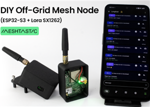 DIY Meshtastic Using ESP32 : Build Your Own Private Off-Grid Network
Project OverviewThis project delivers a complete, custom-designed PCB solution for building Meshtast...
-
 Second PCB for ESP32 Smart Watch
This project contains two PCBs, this is the Second PCB,and there is a Main PCB, please click https:/...
-
 1S battery Charger with Battery level indicator and power path
1S Battery Charger with Battery level indicator and 5V out and standby mode.
-
 Smart Universal Remote with Learning Function and Google Assistant Support
In our day-to-day life, we use various gadgets such as televisions, set-top boxes, air conditioners,...
-
 High-Resolution POV Display using ESP32
In this guide, we'll learn how to create a cool POV display using an ESP32 module. It's all about us...
-
 Low Cost Drone using ESP32
Drones have rapidly evolved from niche hobbies to versatile tools with a wide range of applications,...
-
ARPS-2 – Arduino-Compatible Robot Project Shield for Arduino UNO
76 0 0 -
A Compact Charging Breakout Board For Waveshare ESP32-C3
546 3 4 -
AI-driven LoRa & LLM-enabled Kiosk & Food Delivery System
536 2 0 -
-
-
-
ESP32-C3 BLE Keyboard - Battery Powered with USB-C Charging
743 0 1 -
-
mammoth-3D SLM Voron Toolhead – Manual Drill & Tap Edition
709 0 1 -
-
AEL-2011 Power Supply Module
1386 0 2


