


ESP8266 Nodemcu 4 Ch Relay Module For IoT Project
Overview
This project allows you to control four relays using an ESP8266 (NodeMCU) via the Arduino IoT Cloud. You can toggle relays using physical switches or control them remotely from anywhere using a cloud-based dashboard.
🎯 Key Features:
✅ Manual Control – Use physical switches to toggle relays.
✅ Remote Control – Control the relays from the Arduino IoT Cloud Dashboard.
✅ WiFi Connectivity – Get real-time feedback on the relay status.
✅ Synchronization – Changes from manual and cloud control stay updated.
Circuit Diagram
🖼️ Follow the wiring diagram below to connect your components:

Wiring Details:
Relays:
Relay 1: GPIO 5 (D1)
Relay 2: GPIO 4 (D2)
Relay 3: GPIO 15 (D8)
Relay 4: GPIO 13 (D7)
Switches:
Switch 1: GPIO 0 (D3)
Switch 2: GPIO 2 (D4)
Switch 3: GPIO 14 (D5)
Switch 4: GPIO 12 (D6)
Step-by-Step Instructions
1️⃣ Install Required Libraries
Open the Arduino IDE and install the following libraries via the Library Manager:
ArduinoIoTCloud
Arduino_ConnectionHandler
2️⃣ Configure Arduino IoT Cloud
Go to Arduino IoT Cloud and create a new Thing.
Add the following Cloud Variables:
relay1 (type: CloudSwitch)
relay2 (type: CloudSwitch)
relay3 (type: CloudSwitch)
relay4 (type: CloudSwitch)
Link these variables to a toggle switch in the dashboard.
3️⃣ Upload the Code to ESP8266
Connect the ESP8266 to your computer.
Upload the following Arduino Sketch (after replacing WiFi credentials and Cloud Keys):
#define RelayPin1 5 // D1 #define RelayPin2 4 // D2 #define RelayPin3 15 // D8 #define RelayPin4 13 // D7 #define SwitchPin1 0 // D3 #define SwitchPin2 2 // D4 #define SwitchPin3 14 // D5 #define SwitchPin4 12 // D6 CloudSwitch relay1; CloudSwitch relay2; CloudSwitch relay3; CloudSwitch relay4; void setup() { pinMode(RelayPin1, OUTPUT); pinMode(RelayPin2, OUTPUT); pinMode(RelayPin3, OUTPUT); pinMode(RelayPin4, OUTPUT); pinMode(SwitchPin1, INPUT_PULLUP); pinMode(SwitchPin2, INPUT_PULLUP); pinMode(SwitchPin3, INPUT_PULLUP); pinMode(SwitchPin4, INPUT_PULLUP); } void loop() { if (digitalRead(SwitchPin1) == LOW) { relay1 = !relay1; digitalWrite(RelayPin1, relay1 ? LOW : HIGH); } }
4️⃣ Test Your Project
Press the physical switches to control the relays.
Use the Arduino IoT Cloud Dashboard to toggle the relays remotely.
Future Improvements
🔹 Add real-time feedback (LEDs for relay status).
🔹 Expand control for more devices.
🔹 Add timer scheduling for automation.

ESP8266 Nodemcu 4 Ch Relay Module For IoT Project
Project images are for reference only. Actual production is based on the manufacturing files on the project page.
Please review the designer's notes (e.g., PCB thickness) and select the appropriate options.
PCBWay is not responsible
for issues caused by unsuitable parameter selections.
For more important ordering information, please refer to
Read More


Raspberry Pi 5 7 Inch Touch Screen IPS 1024x600 HD LCD HDMI-compatible Display for RPI 4B 3B+ OPI 5 AIDA64 PC Secondary Screen(Without Speaker)
BUY NOW


- Comments(0)
- Likes(1)
More by MANORANJAN DAS
-
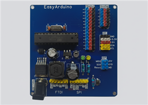 EasyArduino
 by ElectroIoTThe ultimate beginner’s board to learn, build, and master Arduino the easy ...
EasyArduino
EasyArduino by ElectroIoTThe ultimate beginner’s board to learn, build, and master Arduino the easy ...
-
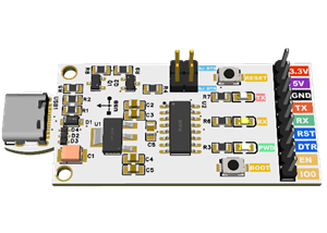 🚀 ESP & Arduino Universal USB Flasher (CH340C Based)
OverviewThis project is a universal USB-to-Serial flasher board based on the CH340C USB-UART bridge....
🚀 ESP & Arduino Universal USB Flasher (CH340C Based)
OverviewThis project is a universal USB-to-Serial flasher board based on the CH340C USB-UART bridge....
-
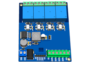 Advanced 4-Channel 5V Relay Module with Onboard LM2596 Power Supply
IntroductionRelay modules are essential in home automation and electronics projects, allowing microc...
Advanced 4-Channel 5V Relay Module with Onboard LM2596 Power Supply
IntroductionRelay modules are essential in home automation and electronics projects, allowing microc...
-
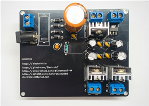
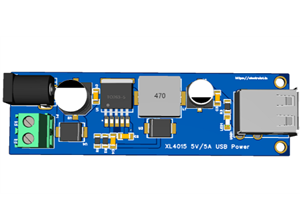 DIY XL4015 5V/5A USB Power Supply – Perfect for Raspberry Pi & More
Building a reliable 5V power ...
DIY XL4015 5V/5A USB Power Supply – Perfect for Raspberry Pi & More
DIY XL4015 5V/5A USB Power Supply – Perfect for Raspberry Pi & MoreBuilding a reliable 5V power ...
-
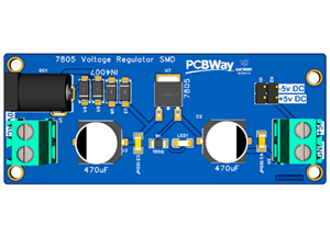 7805 Voltage Regulator SMD
Story️ Project DetailsName: 7805 Voltage RegulatorType: Linear Voltage RegulatorInput Voltage: 7V to...
7805 Voltage Regulator SMD
Story️ Project DetailsName: 7805 Voltage RegulatorType: Linear Voltage RegulatorInput Voltage: 7V to...
-
 Multi-Voltage-Regulator-PCB-(12V-9V-5V-3.3V)
Multi-Voltage Regulator PCB (12V, 9V, 5V, 3.3V) Project OverviewThis project demonstrates the design...
Multi-Voltage-Regulator-PCB-(12V-9V-5V-3.3V)
Multi-Voltage Regulator PCB (12V, 9V, 5V, 3.3V) Project OverviewThis project demonstrates the design...
-
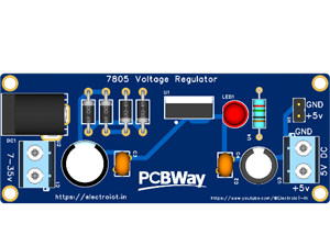 7805 Voltage Regulator
Project OverviewThis project demonstrates how to build a simple Voltage Regulator using the 7805 int...
7805 Voltage Regulator
Project OverviewThis project demonstrates how to build a simple Voltage Regulator using the 7805 int...
-
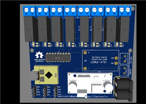 🔌 ESP32-C3-Based 8-Channel Smart Home Automation Relay Board
Detailed Project DescriptionThis project is a compact, powerful, and cost-effective 8-channel smart ...
🔌 ESP32-C3-Based 8-Channel Smart Home Automation Relay Board
Detailed Project DescriptionThis project is a compact, powerful, and cost-effective 8-channel smart ...
-
 ESP8266 NTP Clock with 16x2 I2C LCD Display
This project uses an ESP8266 NodeMCU to create a 12-hour format NTP clock with AM/PM, date, and day ...
ESP8266 NTP Clock with 16x2 I2C LCD Display
This project uses an ESP8266 NodeMCU to create a 12-hour format NTP clock with AM/PM, date, and day ...
-
 ESP8266 Nodemcu 4 Ch Relay Module For IoT Project
OverviewThis project allows you to control four relays using an ESP8266 (NodeMCU) via the Arduino Io...
ESP8266 Nodemcu 4 Ch Relay Module For IoT Project
OverviewThis project allows you to control four relays using an ESP8266 (NodeMCU) via the Arduino Io...
-
 ESP32 Water Level Monitor And Automictic Motor Control 30A relay
Used ESP32 ModuleOled DisplayUltraso...
ESP32 Water Level Monitor And Automictic Motor Control 30A relay
ESP32 Water Level Monitor And Automictic Motor Control 30A relayUsed ESP32 ModuleOled DisplayUltraso...
-
 4 CH Relay Module With ESP32 For Home Automation ,Alexa,Google Home
Hello All My FriendThis is Simple Easy To USE 4 Ch Relay Module With ESP32 SupportUse This Board For...
4 CH Relay Module With ESP32 For Home Automation ,Alexa,Google Home
Hello All My FriendThis is Simple Easy To USE 4 Ch Relay Module With ESP32 SupportUse This Board For...
-
 8Ch Relay With ESP8266 Wemos D1 Mini Work With Amazon Alexa And Google Home
This Project8Ch Relay With ESP8266 Wemos D1 Mini Work With Amazon Alexa And Google HomeSimple parts ...
8Ch Relay With ESP8266 Wemos D1 Mini Work With Amazon Alexa And Google Home
This Project8Ch Relay With ESP8266 Wemos D1 Mini Work With Amazon Alexa And Google HomeSimple parts ...
-
 PiTrezor : A DIY bitcoin hardware wallet based on trezor and raspberry pi zero
Hello Everyone This is One Of Best Project Who Want To Make OWN hardware wallet At low Cost or Make ...
PiTrezor : A DIY bitcoin hardware wallet based on trezor and raspberry pi zero
Hello Everyone This is One Of Best Project Who Want To Make OWN hardware wallet At low Cost or Make ...
-
 100mm X 50nn DIY Universal Board
100mm X 50nn DIY Universal Board
100mm X 50nn DIY Universal Board
-
 Simple Internet Clock Using ESP8266 DHT11
Hello Everyone This Project is Simple Internet Clock Using Esp8266 And DHT11 Upload Video And More T...
Simple Internet Clock Using ESP8266 DHT11
Hello Everyone This Project is Simple Internet Clock Using Esp8266 And DHT11 Upload Video And More T...
-
 Micro USB FTDI Board With Dual Header
Micro USB FTDI Board With Dual Header
Micro USB FTDI Board With Dual Header
-
 Micro USB FTDI Module FT232RL
Hello Everyone All FTDi Module In Market is Mini USB Version And Its Little Complicated To Find Mini...
Micro USB FTDI Module FT232RL
Hello Everyone All FTDi Module In Market is Mini USB Version And Its Little Complicated To Find Mini...
-
Programmable Mist Maker - XIAO / QT PY Extension
1067 2 1 -
RadioHAT - Raspberry Pi radio development platform
882 0 2 -
-
-
-
-
ARPS-2 – Arduino-Compatible Robot Project Shield for Arduino UNO
3332 0 6 -
A Compact Charging Breakout Board For Waveshare ESP32-C3
3941 3 8 -
AI-driven LoRa & LLM-enabled Kiosk & Food Delivery System
4326 2 2


