


|
KiCADKicad
|
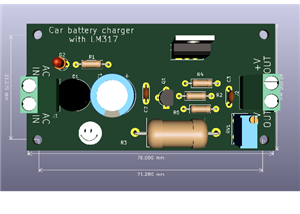
Battery Cell Charger
Circuit Operation
?
The assembly ensures the charging phase with limited current and constant voltage. The low voltage charging current of the transformer passes through the transistor Q1, the diode D7, the battery and the resistor R3 back to the mains supply. The passing current creates a voltage drop in R3, which opens Q2. Transistor TQ controls the current flowing through Q1 - the current is adjusted so that there is approximately a constant voltage drop in R3. LED D5 is connected to collector Q2, which indicates the current charging phase. The resistance of the resistor R1 is intentionally chosen to be relatively low, so that a substantially higher current flows through the resistor than is necessary for the control Q1. Most of this current then flows through LEDs D5 and Q2. Therefore, the LED illuminates at an approximately constant brightness throughout the current charging phase. The D5 LED connection limits the minimum output voltage at which the circuit is operating properly to about 1 V. Since even a discharged battery still has a voltage higher than 3 V, this is not a fault. Part of the output voltage stabilization circuit does not apply during the current charging phase. LED D6 is low and low current. The TL431C stabilizer is only applied when the final voltage is reached. As the voltage increases, the current IO begins to flow, while the current flowing Q2 decreases. The final charging voltage is set by the divider R5, R6 and R7. Resistor R7 is used for precise setting of the output voltage. The function of the TL431C circuit is very simple - if the voltage at input R increases by more than 2.5 V, the current flowing between terminals K and A. The capacitor C2 increases and the resistance R7 ensures the stability of the regulator.
In the constant voltage charging phase, LED D5 goes out (Q2 closes) and LED D6 lights up. The upload procedure is therefore very simple. If LED D6 is lit, the cell is more than 70% charged and we can use it. Conversely, if we leave the cell in the charger, the cell will gradually charge up to 100% and the charging current will gradually drop to zero. Because the batteries do not have any memory phenomena, partial discharge and charging do not damage them. Transistor Q1 is used as a power element to regulate voltage and current. Diode D7 restricts battery discharge when the battery is connected to a charger and not connected to the mains.
Transistor Q1 is equipped with a small radiator. However, with the components used, the loss on Q1 is very small. LEDs are of the low current (2 mA) type. Adjusting the charger is very easy. Without the battery connected, check the output voltage, it must be as accurate as 4.2 V (or 4.1 V for older cells). If not, replace the R7 with another 180, 200, 240 or 270 kOhm resistor. The output voltage must be measured on a quality instrument. If we need a final voltage of 4.2 V, we omit the R7 resistor completely. We check the charging current by connecting such a load to the output, so that the voltage drops below 4V. The charging current can be adjusted by changing the resistance R3. With a resistance of 2.2 ohms, the charging current was about 220 mA. If you set a higher charging current than the transformer can provide, the D5 LED will not light up during charging. The charging current is then not limited by the charger, but by the power of the transformer. It does not affect the function of the charger.
Bill of materials available in the download section.

Battery Cell Charger
Project images are for reference only. Actual production is based on the manufacturing files on the project page.
Please review the designer's notes (e.g., PCB thickness) and select the appropriate options.
PCBWay is not responsible
for issues caused by unsuitable parameter selections.
For more important ordering information, please refer to
Read More


Raspberry Pi 5 7 Inch Touch Screen IPS 1024x600 HD LCD HDMI-compatible Display for RPI 4B 3B+ OPI 5 AIDA64 PC Secondary Screen(Without Speaker)
BUY NOW


- Comments(0)
- Likes(0)
 More by cris 🙂
-
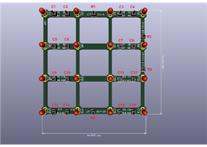
 Dynamic decoration with LEDs and more
Hello everyone!As you can see in the title, we have a circuit with LEDs, many LEDs, it's a 4x4 LEDs ...
Dynamic decoration with LEDs and more
Hello everyone!As you can see in the title, we have a circuit with LEDs, many LEDs, it's a 4x4 LEDs ...
-
 LEDs Stars
Hello everyone! I'm signing up for this competition with a small project designed to attract your a...
LEDs Stars
Hello everyone! I'm signing up for this competition with a small project designed to attract your a...
-
 Audio amplifier with LM386 (and BASS boost)
Hello everyone!Circuit descriptionThe LM386 is quite a ve...
Audio amplifier with LM386 (and BASS boost)
Audio amplifier with LM386 (and BASS boost)Hello everyone!Circuit descriptionThe LM386 is quite a ve...
-
 Audio amplifier 25W TDA2030
A fairly well-known and interesting montagePresentationThe presented audi...
Audio amplifier 25W TDA2030
Audio amplifier 25W TDA2030A fairly well-known and interesting montagePresentationThe presented audi...
-
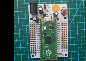 Raspberry Pi Pico Expansion Board
Hello everyone!UPDATE!!!I made some changes, routing in particular, and freed up the board of a few ...
Raspberry Pi Pico Expansion Board
Hello everyone!UPDATE!!!I made some changes, routing in particular, and freed up the board of a few ...
-
 Adjustable voltage power supply
Among the most important electronic devices in the electronics laboratory is the voltage source. Thi...
Adjustable voltage power supply
Among the most important electronic devices in the electronics laboratory is the voltage source. Thi...
-
 Digital Clock with AT89C2051
Circuit OperationShort SW2 presses cycle through displaying the current time in HH:MM and MM:SS form...
Digital Clock with AT89C2051
Circuit OperationShort SW2 presses cycle through displaying the current time in HH:MM and MM:SS form...
-
 Switch based light sensor
Hi!The circuit shown can be used to turn on the light in the garden, or some light panels / advertis...
Switch based light sensor
Hi!The circuit shown can be used to turn on the light in the garden, or some light panels / advertis...
-
 LM3909 flashing indicator
I present to you a circuit which is a little outdated, but quite pleasant for some, I saw that this ...
LM3909 flashing indicator
I present to you a circuit which is a little outdated, but quite pleasant for some, I saw that this ...
-
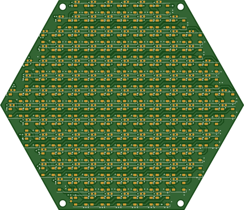 Hexagonal Panel with WS2812B LEDs
Hi makers!I created a hexagonal PCB with many WS2812B LEDs, 144 in total, for which I thought of pla...
Hexagonal Panel with WS2812B LEDs
Hi makers!I created a hexagonal PCB with many WS2812B LEDs, 144 in total, for which I thought of pla...
-
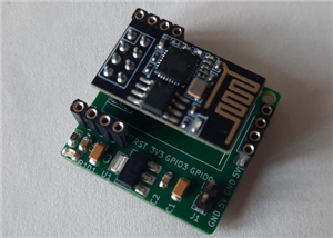
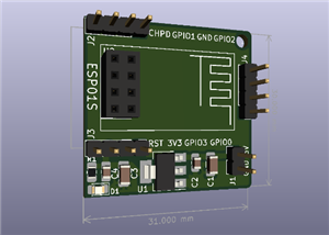 ESP01S Minimal Board
Hi makers!I created this small PCB for ESP01S because before I was using a DIY version and then I bo...
ESP01S Minimal Board
Hi makers!I created this small PCB for ESP01S because before I was using a DIY version and then I bo...
-
 4x4x4 cube with blue LEDs
Hi makers!I know that these days there are many variations of LEDs, for example SMDs are smaller and...
4x4x4 cube with blue LEDs
Hi makers!I know that these days there are many variations of LEDs, for example SMDs are smaller and...
-
 Low cost turntable 😁
Hi makers!I'm entering this competition with a small project that I've wanted to make for some time,...
Low cost turntable 😁
Hi makers!I'm entering this competition with a small project that I've wanted to make for some time,...
-
 A DIY charger for 12V battery
Hello everyone!I present to you a project that really didn't reach its final state, until recently. ...
A DIY charger for 12V battery
Hello everyone!I present to you a project that really didn't reach its final state, until recently. ...
-
 ESP01 board
Hello PCBWayers!You probably know that ESP01S/01 boards can be a little difficult to use in an easie...
ESP01 board
Hello PCBWayers!You probably know that ESP01S/01 boards can be a little difficult to use in an easie...
-
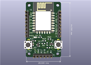 ESP12F Board
Hello makers!Some time ago I had a shopping coupon and I thought about making some simple PCBs with ...
ESP12F Board
Hello makers!Some time ago I had a shopping coupon and I thought about making some simple PCBs with ...
-
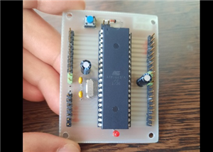 ATMega32 Board
Hi !I remembered this simple project I made for myself, you can use it with an ATMega32 or ATMega16 ...
ATMega32 Board
Hi !I remembered this simple project I made for myself, you can use it with an ATMega32 or ATMega16 ...
-
 AT90CAN128
Hello makers!Here is a guy who likes to build various, small, electronic circuits, and through this ...
AT90CAN128
Hello makers!Here is a guy who likes to build various, small, electronic circuits, and through this ...
-
Programmable Mist Maker - XIAO / QT PY Extension
952 1 0 -
RadioHAT - Raspberry Pi radio development platform
772 0 2 -
-
-
-
-
ARPS-2 – Arduino-Compatible Robot Project Shield for Arduino UNO
3228 0 6 -
A Compact Charging Breakout Board For Waveshare ESP32-C3
3856 3 8 -
AI-driven LoRa & LLM-enabled Kiosk & Food Delivery System
4208 2 2


