


|
|
Arduino® Nano V3Arduino
|
x 1 | |
|
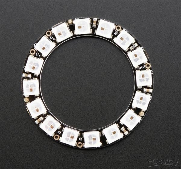
16 Pixel Neopixel Ring |
x 1 |
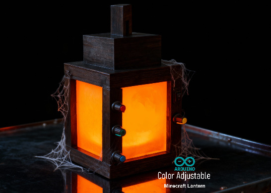
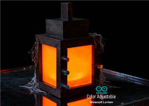
Arduino Based 3D Printed Color Adjustable Minecraft Lantern
For this Halloween, I'm fusing the creative blocky world of Minecraft with the spooky glow of the colorful RGB LEDs in a fun and simple Halloween project.
A "Color Adjustable Minecraft Lantern" is a project that recreates the iconic lantern from the video game Minecraft. It allows the user to change the light's color to any hue, rather than being limited to the standard yellow or orange glow.
Video: https://www.youtube.com/watch?v=8wauoKaCeak
Components Required

For this project we need:
[Buy Now] 1 x Arduino Nano : https://s.click.aliexpress.com/e/_c4bnXuZ9
[Buy Now] 2 x WS2812B 16 LEDs NeoPixel Ring : https://s.click.aliexpress.com/e/_onkX369
[Buy Now] 4 x 10kΩ Rotary Potentiometer : https://s.click.aliexpress.com/e/_c34dRQBp
[Buy Now] 1 x 1000µF capacitor is highly recommended to smooth out voltage spikes and dips : https://s.click.aliexpress.com/e/_c2wubSZH
[Buy Now] 1 x 100Ω Resistor placed in series on the data line to limit the current and dampen signal reflections : https://s.click.aliexpress.com/e/_c3S3GhXz
[Buy Now] 1 x SPST Switch: https://s.click.aliexpress.com/e/_c4BLnrPN
[Buy Now] 1 x 18650 Battery and a Holder : https://s.click.aliexpress.com/e/_c30JZ20T
[Buy Now] 1 x TP4056 Battery Charging Module: https://s.click.aliexpress.com/e/_c2J3ccYT
[Buy Now] 1 x DC-to-DC Buck Converter : https://s.click.aliexpress.com/e/_c4kyXg8b
[Buy Now] Jumper Wires & Breadboard
and a 3D printer to print the enclosure
Wiring Diagram

The setup consists of three simple circuits:
1. First, the power circuit: a battery that charges and runs the Arduino Nano
2. Second, the control circuit: a potentiometer feeding signal to the Arduino
3. And third, the light circuit: the NeoPixels, which lights up based on the instructions received from the Arduino
Explanation of operation:
The Arduino reads the potentiometers via its analog pins, generating values from 0 to 1023. This range is then mapped to 0-255 to comply with the Arduino library. The converted signal is then sent sequentially to the LEDs, lighting them up one by one from first to the last.
Two key components are required for signal integrity: a 1000µF capacitor closest to the load to stabilize the voltage, and a 100Ω resistor on the data line to protect against current surges and dampen signal noise.
[[In general, caps are for 3 things. To provide a reservoir of current to keep voltage stable, to bypass noise to ground and to pass AC signals while blocking DC. The third is of no use in this context, but the other 2 are. Higher value caps are used as reservoirs (ie.1000uF) and lower values to bypass noise (0.1uF, 1uF). As a rule of thumb, caps should be placed close to where the problem that they are to solve occurs]]
The Code

The code begins by including the Adafruit NeoPixel library and by defining the necessary pins and global variables.
In the setup() section, we initialize the NeoPixel library and immediately run a rainbow cycle across the entire LED ring to confirm it's working.
The loop() section continuously reads the potentiometer value, mapping it from a 0-1023 range to 0-255. You'll notice that I commented out the brightness control section. This is because, during my testing, I found that the NeoPixel library's brightness setting proportionally scales all RGB values, which significantly alters the LEDs' perceived color and intensity.
Important Considerations
Color Perception: Lower brightness can make colors appear different than expected
Power Consumption: Lower brightness = less power used
Heat Generation: Lower brightness reduces heat
Eye Comfort: Very bright NeoPixels can be uncomfortable to look at
Finally, the code uses the mapped potentiometer values to set the pixel colors and updates the LED display. This creates a direct, real-time control between the potentiometers and the LED output.
Breadboard Testing

Before putting everything into the enclosure, I hooked them up on a breadboard to test the code. When I power it on, you can see the NeoPixel rings plays a little rainbow animation, and then they are ready to go. Now, when I turn these knobs, the colors change smoothly as the Arduino reads the potentiometer values and updates the LEDs in real-time.
3D Design

I designed a custom 6-part enclosure in Microsoft 3D Builder for this project. You can download the STL files from my GitHub repository and have them professionally printed from PCBWay.
The assembly includes:
1. A base for the main components like the battery, Arduino and the battery charger
2. A TP4056 stopper to secure the charging module
3. Four stands to mount the switch and potentiometers
4. Four Perspex panels to diffuse the LED light and hide the electronics
5. Two stand covers to conceal the sides
6. And a top lid to finish the enclosure
After finalizing the design, I proceeded to 3D print all the required components for the assembly. These are all the custom components I'll need to assemble the final unit.
Assembly

With all the 3D models printed, I began assembling the electronic components.
I soldered wires to each potentiometers and the SPST switch, then mounted them into their designated stands. Each potentiometer was secured by tightening its screw, with its wires routed through a small hole in the side of the stand. Similarly, the switch was pressed into its hole, and its wires were fed through the corresponding wire channel.
Next, I focused on the battery charging bit of the circuit. I soldered the battery to the B+ and B- ports of the TP4056 charging module. A blue wire was used to connect the OUT- of the TP4056 to the VIN- of the buck converter, while the SPST switch was wired to control the connection between the OUT+ and VIN+ terminals.
Once these connections were complete, I installed the power components into the base of the unit. The TP4056 module was secured by supergluing a stopper behind it after sliding it into place, and I also super glued the stand holding the on-of switch to the base.
For the control system, I soldered all the necessary components for the Arduino onto a perfboard. While the setup may appear messy, the final assembly will be fully enclosed. I then hot-glued the two NeoPixel rings into position, the first one to the base and the second one to the top. After supergluing the 2nd stand I concealed the electronics by supergluing the 'side covers' to it.

Before installing the perspex panels I painted the body of the lantern with black acrylic color. After the paint dried, I inserted the perspex panels and superglued the top into place to complete the build.
Demo

So, this is how my final setup looks like.
This is a classic way to create an interactive project where you turn a knob to change the behavior of the lights. The microcontroller reads the potentiometer's position, converts it to a value, and then uses that value to change something about the NeoPixels (e.g., brightness, color or speed).
This project encourages children to experiment with the primary colors to see what new shades they can create.
Let me know what you think.
Feel free to like, share, and comment if you have any suggestions for improvement!
Thanks
Thanks again for checking my post. I hope it helps you.
If you want to support me subscribe to my YouTube Channel: https://www.youtube.com/@CrazyCoupleDIY
Video: https://youtu.be/8wauoKaCeak
Full Blog Post: https://diyfactory007.blogspot.com/2025/10/Minecraft-Lantern.html
Github: https://github.com/tarantula3/RGB-Minecraft-Lantern
Support My Work
BTC: 1Hrr83W2zu2hmDcmYqZMhgPQ71oLj5b7v5
LTC: LPh69qxUqaHKYuFPJVJsNQjpBHWK7hZ9TZ
DOGE: DEU2Wz3TK95119HMNZv2kpU7PkWbGNs9K3
ETH: 0xD64fb51C74E0206cB6702aB922C765c68B97dCD4
BAT: 0x9D9E77cA360b53cD89cc01dC37A5314C0113FFc3
LBC: bZ8ANEJFsd2MNFfpoxBhtFNPboh7PmD7M2
COS: bnb136ns6lfw4zs5hg4n85vdthaad7hq5m4gtkgf23 Memo: 572187879
BNB: 0xD64fb51C74E0206cB6702aB922C765c68B97dCD4
MATIC: 0xD64fb51C74E0206cB6702aB922C765c68B97dCD4
Thanks, ca again in my next tutorial.
Arduino Based 3D Printed Color Adjustable Minecraft Lantern


Raspberry Pi 5 7 Inch Touch Screen IPS 1024x600 HD LCD HDMI-compatible Display for RPI 4B 3B+ OPI 5 AIDA64 PC Secondary Screen(Without Speaker)
BUY NOW


- Comments(2)
- Likes(2)
More by Ashish Adhikari
-
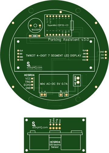 Arduino Parking Assistant V3
The ESP32-C3 Based Parking Assistant is an advanced parking sensor system that utilizes the ESP32-C3...
Arduino Parking Assistant V3
The ESP32-C3 Based Parking Assistant is an advanced parking sensor system that utilizes the ESP32-C3...
-
 100 LED Chaser Circuit Using IC555 and CD4017
A Chaser Circuit consists of a clocked IC or other electronic unit like an Arduino that drives an ar...
100 LED Chaser Circuit Using IC555 and CD4017
A Chaser Circuit consists of a clocked IC or other electronic unit like an Arduino that drives an ar...
-
 Cute Medusa 3D Printed Humidifier
Humidifiers add moisture to the air. They can help people with dry skin, allergies, and respiratory ...
Cute Medusa 3D Printed Humidifier
Humidifiers add moisture to the air. They can help people with dry skin, allergies, and respiratory ...
-
 4x4x4 PCB LED CUBE
Note from PCBWay: This project includes two PCBs, if both need to be produced, please inform your sa...
4x4x4 PCB LED CUBE
Note from PCBWay: This project includes two PCBs, if both need to be produced, please inform your sa...
-
 Getting Started With Raspberry Pi Pico
Couple of months ago, I bought a "Raspberry Pi Pico" to get some hands-on experience of it and to cr...
Getting Started With Raspberry Pi Pico
Couple of months ago, I bought a "Raspberry Pi Pico" to get some hands-on experience of it and to cr...
-
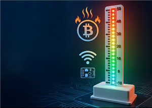 Programmable RGB Thermometer
Summer has been relentless this year. My passion for Bitcoin mining took a major hit due to the imme...
Programmable RGB Thermometer
Summer has been relentless this year. My passion for Bitcoin mining took a major hit due to the imme...
-
 All About PC817 Optocoupler
An Optocoupler also known as Photocoupler or Optical Isolator is a component that transfers electric...
All About PC817 Optocoupler
An Optocoupler also known as Photocoupler or Optical Isolator is a component that transfers electric...
-
 Make Your Own 3D Printed Diwali Diyas at Home
Diyas are the heart of major Indian festivals, most notably Diwali, the "Festival of Lights." Lighti...
Make Your Own 3D Printed Diwali Diyas at Home
Diyas are the heart of major Indian festivals, most notably Diwali, the "Festival of Lights." Lighti...
-
 Arduino Based 3D Printed Color Adjustable Minecraft Lantern
For this Halloween, I'm fusing the creative blocky world of Minecraft with the spooky glow of the co...
Arduino Based 3D Printed Color Adjustable Minecraft Lantern
For this Halloween, I'm fusing the creative blocky world of Minecraft with the spooky glow of the co...
-
 3D Printed Breathing IC555 LED Trophy
This project features a custom 3D-printed 'Mortal Kombat' trophy shell paired with a basic NE555 tim...
3D Printed Breathing IC555 LED Trophy
This project features a custom 3D-printed 'Mortal Kombat' trophy shell paired with a basic NE555 tim...
-
 Destiny Internet Ghost - Internet Notifier
The Internet has changed the way we live our lives. From communication, education, banking, entertai...
Destiny Internet Ghost - Internet Notifier
The Internet has changed the way we live our lives. From communication, education, banking, entertai...
-
 Liquid level indicator Using ULN2003
A water level indicator detects and indicates the level of water in an overhead tank and relays the ...
Liquid level indicator Using ULN2003
A water level indicator detects and indicates the level of water in an overhead tank and relays the ...
-
 All About IC UNL2003
The UNL2003 IC contains 7 High Voltage, High Current NPN Darlington Transistor Arrays each rated at ...
All About IC UNL2003
The UNL2003 IC contains 7 High Voltage, High Current NPN Darlington Transistor Arrays each rated at ...
-
 NodeMCU Based: 3D Printed Indoor Gauge Thermometer
Had some time this weekend and a desire to create something new and interesting, so went ahead and c...
NodeMCU Based: 3D Printed Indoor Gauge Thermometer
Had some time this weekend and a desire to create something new and interesting, so went ahead and c...
-
 Rechargeable Gothic Lantern
A Gothic Lantern is a captivating piece of lighting that brings the allure of the Victorian Era into...
Rechargeable Gothic Lantern
A Gothic Lantern is a captivating piece of lighting that brings the allure of the Victorian Era into...
-
 555 Adjustable Delay On Off Timer Circuit
The 555 timer IC is an integrated circuit (IC) that is used in a variety of timer, delay, pulse gene...
555 Adjustable Delay On Off Timer Circuit
The 555 timer IC is an integrated circuit (IC) that is used in a variety of timer, delay, pulse gene...
-
 3D Printed Arduino Halloween Décor
When the full moon is shining and the wolves are howling, it's time for Halloween's spooky spectacle...
3D Printed Arduino Halloween Décor
When the full moon is shining and the wolves are howling, it's time for Halloween's spooky spectacle...
-
 All About RCWL-0516 Microwave Radar Motion Sensor
Proximity sensing is a very common application in electronics.There are several ways to accomplish t...
All About RCWL-0516 Microwave Radar Motion Sensor
Proximity sensing is a very common application in electronics.There are several ways to accomplish t...
-
-
ARPS-2 – Arduino-Compatible Robot Project Shield for Arduino UNO
2155 0 5 -
A Compact Charging Breakout Board For Waveshare ESP32-C3
2663 3 7 -
AI-driven LoRa & LLM-enabled Kiosk & Food Delivery System
2837 2 0 -
-
-
-
ESP32-C3 BLE Keyboard - Battery Powered with USB-C Charging
2865 0 2 -


