


|
|
ESP32-C3 Super Mini |
x 1 | |
|
|
HC-SR04 |
x 1 | |
|
|
24 LED NeoPixel Ring |
x 1 | |
|
|
TM1637 |
x 1 | |
|
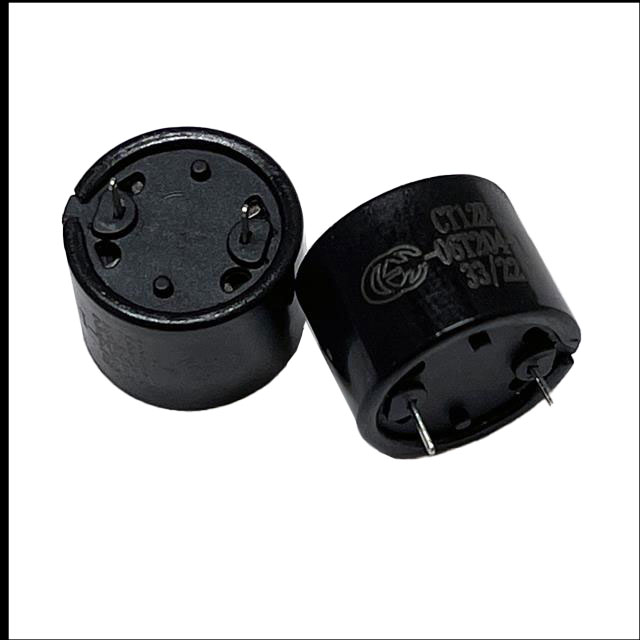
CT12E-06T204-1Challenge Electronics
|
x 1 | |
|
|
100 ohm Resistor |
x 1 | |
|
|
AC-DC 5V Adapter |
x 1 |
Arduino Parking Assistant V3
The ESP32-C3 Based Parking Assistant is an advanced parking sensor system that utilizes the ESP32-C3 super-mini micro-controller to provide accurate distance measurements and parking assistance.
This is the third iteration of my previously released parking assistant videos.
This parking assistant system uses ultrasonic sensors to help drivers park their vehicles accurately by providing visual and audible feedback about distance to the obstacles.
Components Required

- For this project I am using an ESP32-C3 Super Mini single core microcontroller which has a small formfactor and also includes Wi-Fi and Bluetooth (Arduino Uno or similar microcontroller).https://s.click.aliexpress.com/e/_omnke4z
- A HC-SR04 Ultrasonic Sensors (3-4 units) https://s.click.aliexpress.com/e/_ol2Np4t
- A 24 LED NeoPixel Ring https://s.click.aliexpress.com/e/_onkX369
- A TM1637 7-Segment display https://s.click.aliexpress.com/e/_o2Dm6fT
- A Buzzer https://s.click.aliexpress.com/e/_olXJAb3
- A 100 ohm Resistor https://s.click.aliexpress.com/e/_oCj0LAz
- A mini AC-DC 5V Adapter https://s.click.aliexpress.com/e/_ooQJdvj
- And mounting hardware printed using a 3D printer
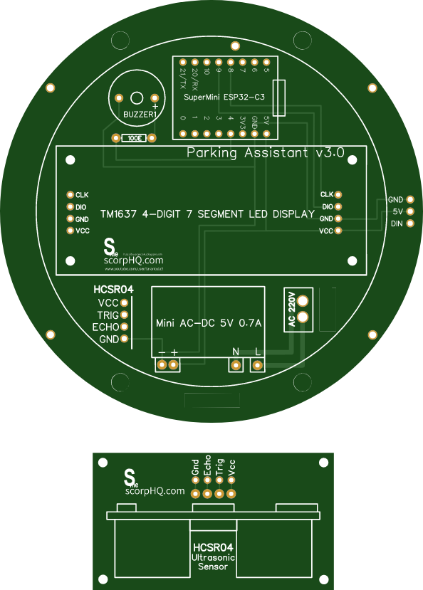
Circuit Diagram

The wiring setup is pretty straightforward:
Connect the microcontroller's Pin 4 to the buzzer
Connect Pin 3 to the NeoPixel ring
Wire Pin 2 to the Trig pin and Pin 1 to the Echo pin of the ultrasonic sensor
Connect Pin 8 to CLK and Pin 9 to DIO of the TM1637 7-segment display
Finally, connect all the positive (+) terminals to the power rail and all negative (-) terminals to ground
Breadboard Testing

Board and Library
-------------------
For the project to function, we first need to install the "ESP32-C3" board from the board manager. Additionally, we need to install the "TM1637Display.h" and "Adafruit_NeoPixel.h" libraries via the library manager.
I began by testing each component individually with the ESP32-C3 board to verify their functionality. Once all modules were confirmed to be working, I connected all of them to the ESP32 board and uploaded the program to orchestrate their combined operation. All source codes for this project are available on my GitHub repository.
We'll begin the "Parking Assistant" code by importing all the required libraries. Then, in the variable declaration section, we will define all pin numbers and the initial sensor values, making them globally accessible.
In the setup() section, the code first establishes a Wi-Fi connection to my Raspberry Pi-based home server. This feature is optional and can be disabled simply by removing or commenting out the relevant code section.
Following the network initialization, all pin modes (INPUT/OUTPUT) are defined, and the necessary hardware modules are initialized.
The loop() section operates continuously, performing two primary tasks:
It reads the distance from the ultrasonic sensor and outputs the value to the 7-segment display.
It also controls the NeoPixel LED color and number based on the measured distance, providing a visual indication of the approaching vehicle.
The system detects when the vehicle is stationary by monitoring for a stable distance reading. Once parked, the NeoPixels enter a "rainbow" animation mode before both the 7-segment display and NeoPixels power down.
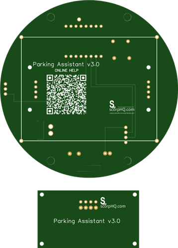
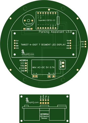
The Board

This is the 2D and 3D representation of my board. Initially, I designed it with just the circular PCB, but in the final iteration, I incorporated an additional PCB dedicated to the ultrasonic sensor.
If you'd like to get started with PCB design, I have a step-by-step guide in "Tutorial No. 45: Transformers PCB BADGE", the link is in the description below.
Soldering

Lets starts by soldering the resistance to the board. Then lets solder the ESP32-C3 microcontroller to the board. Since I care a lot about my ICs and micro-controllers, I never solder them directly to the board. In case of an ICs, I always try to use IC bases or if a base is not available I use female pin-headers. (This avoids direct soldering and allows for easy replacement).
Then, let solder the buzzer followed by the AC-DC 5V Adapter to the board. Once thats done let solder the 7-Segment display to the board followed by the NeoPixel Ring. To maintain the height I added few supports to keep the ring affloat.
The 220V power supply will be connected to these ports and the Ultrasonic sensor will connect to these ports via a 1M long cable.

Note: While a resistor isn't strictly required for WS2812 LEDs, it's often recommended to include one on the data line, especially for longer strips, to ensure reliable operation and protect the first LED from voltage spikes. A resistor between 220 ohms and 1k ohm is typically used.
3D Printing

I created the 3D model for this project using Microsoft 3D Builder. The top section is made up of four key components:
- Main Housing – The primary enclosure for the unit.
- Front Covers – Protective panels for the front section.
- Internal Holder – A custom piece to secure the unit inside the housing.
- Back Lid – The rear cover that completes the assembly.
For the bottom section housing the ultrasonic sensor, I used a 3D model originally created by dstark1 from Thingiverse, which I modified to fit into my project.
The 3D printed cover acts as a light-diffusing cover for the NeoPixel ring. Its semi-translucent material softens the bright LEDs, preventing eye strain and protecting the components.
Once all the 3D models were sorted, I went ahead and printed them using my 3D printer.
Assembly

To complete the setup, assemble the 3D-printed enclosure and insert the electronics into it. Mount the ultrasonic sensor on the garage wall at bumper height for accurate detection, and install the LED strip where it is clearly visible to the driver. Calibrate the system by testing with objects at known distances and adjust the SAFE_DISTANCE, WARNING_DISTANCE, and DANGER_DISTANCE values in the code accordingly. Finally, fine-tune the buzzer’s frequency and duration for optimal alerts.
Demo

When the unit boots up, the LEDs flash in rainbow colors and then switch to displaying a color based on the proximity. The distance is also shown on the 7-segment display. If no movement is detected, the LEDs and the 7-segment display turn off.
Beyond standard proximity detection, this version also includes Wi-Fi/Bluetooth connectivity, allowing smartphone integration to monitor distance data via Google Charts.
Let me know what you think.
Feel free to like, share, and comment if you have any suggestions for improvement!

Key Features
Progressive visual feedback - LED color changes from green to red as distance decreases
Audible alerts - Beeping frequency increases as vehicle approaches obstacles
Weather-resistant - design for outdoor use
HC-SR04 Ultrasonic Sensor:
Maximum Range - 4 meters
Minimum Range - 2 cm
Thanks
Thanks again for checking my post. I hope it helps you.
If you want to support me subscribe to my YouTube Channel: https://www.youtube.com/@CrazyCoupleDIY
- Video: https://youtu.be/rqTDj7GabGw
- Full Blog Post: https://diyfactory007.blogspot.com/2025/08/arduino-parking-assistant-v3.html
- Github: https://github.com/tarantula3/Arduino-Parking-Assistant-V3
References
- Arduino based parking assistant V1: https://youtu.be/LQGhprwuHe0
- Arduino based parking assistant V2: https://youtu.be/MqJxUf3Cugg
- All About TM1637: https://youtu.be/Ob9mrq_Lj9k
- Transformers PCB BADGE: https://youtu.be/vlJoQAzjYDo
Support My Work
- BTC: 1Hrr83W2zu2hmDcmYqZMhgPQ71oLj5b7v5
- LTC: LPh69qxUqaHKYuFPJVJsNQjpBHWK7hZ9TZ
- DOGE: DEU2Wz3TK95119HMNZv2kpU7PkWbGNs9K3
- ETH: 0xD64fb51C74E0206cB6702aB922C765c68B97dCD4
- BAT: 0x9D9E77cA360b53cD89cc01dC37A5314C0113FFc3
- LBC: bZ8ANEJFsd2MNFfpoxBhtFNPboh7PmD7M2
- COS: bnb136ns6lfw4zs5hg4n85vdthaad7hq5m4gtkgf23 Memo: 572187879
- BNB: 0xD64fb51C74E0206cB6702aB922C765c68B97dCD4
- MATIC: 0xD64fb51C74E0206cB6702aB922C765c68B97dCD4
Thanks, ca again in my next tutorial.
Arduino Parking Assistant V3
Project images are for reference only. Actual production is based on the manufacturing files on the project page.
Please review the designer's notes (e.g., PCB thickness) and select the appropriate options.
PCBWay is not responsible
for issues caused by unsuitable parameter selections.
For more important ordering information, please refer to
Read More


Raspberry Pi 5 7 Inch Touch Screen IPS 1024x600 HD LCD HDMI-compatible Display for RPI 4B 3B+ OPI 5 AIDA64 PC Secondary Screen(Without Speaker)
BUY NOW


- Comments(0)
- Likes(1)
More by Ashish Adhikari
-
 Arduino Parking Assistant V3
The ESP32-C3 Based Parking Assistant is an advanced parking sensor system that utilizes the ESP32-C3...
Arduino Parking Assistant V3
The ESP32-C3 Based Parking Assistant is an advanced parking sensor system that utilizes the ESP32-C3...
-
 100 LED Chaser Circuit Using IC555 and CD4017
A Chaser Circuit consists of a clocked IC or other electronic unit like an Arduino that drives an ar...
100 LED Chaser Circuit Using IC555 and CD4017
A Chaser Circuit consists of a clocked IC or other electronic unit like an Arduino that drives an ar...
-
 Cute Medusa 3D Printed Humidifier
Humidifiers add moisture to the air. They can help people with dry skin, allergies, and respiratory ...
Cute Medusa 3D Printed Humidifier
Humidifiers add moisture to the air. They can help people with dry skin, allergies, and respiratory ...
-
 4x4x4 PCB LED CUBE
Note from PCBWay: This project includes two PCBs, if both need to be produced, please inform your sa...
4x4x4 PCB LED CUBE
Note from PCBWay: This project includes two PCBs, if both need to be produced, please inform your sa...
-
 Getting Started With Raspberry Pi Pico
Couple of months ago, I bought a "Raspberry Pi Pico" to get some hands-on experience of it and to cr...
Getting Started With Raspberry Pi Pico
Couple of months ago, I bought a "Raspberry Pi Pico" to get some hands-on experience of it and to cr...
-
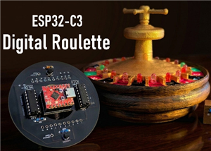 DIY LED Roulette Wheel | ESP32 C3 Project
Hi everyone, today I am going to show you how I made a "Digital Roulette Wheel" by combining ESP32-C...
DIY LED Roulette Wheel | ESP32 C3 Project
Hi everyone, today I am going to show you how I made a "Digital Roulette Wheel" by combining ESP32-C...
-
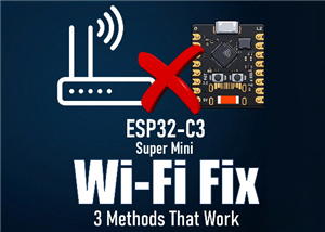 ESP32 C3 Super Mini WiFi Fix - 3 Methods That Work
Hi everyone! I’ve recently started working with a tiny, super affordable microcontroller board calle...
ESP32 C3 Super Mini WiFi Fix - 3 Methods That Work
Hi everyone! I’ve recently started working with a tiny, super affordable microcontroller board calle...
-
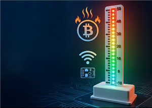 Programmable RGB Thermometer
Summer has been relentless this year. My passion for Bitcoin mining took a major hit due to the imme...
Programmable RGB Thermometer
Summer has been relentless this year. My passion for Bitcoin mining took a major hit due to the imme...
-
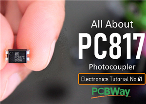 All About PC817 Optocoupler
An Optocoupler also known as Photocoupler or Optical Isolator is a component that transfers electric...
All About PC817 Optocoupler
An Optocoupler also known as Photocoupler or Optical Isolator is a component that transfers electric...
-
 Make Your Own 3D Printed Diwali Diyas at Home
Diyas are the heart of major Indian festivals, most notably Diwali, the "Festival of Lights." Lighti...
Make Your Own 3D Printed Diwali Diyas at Home
Diyas are the heart of major Indian festivals, most notably Diwali, the "Festival of Lights." Lighti...
-
 Arduino Based 3D Printed Color Adjustable Minecraft Lantern
For this Halloween, I'm fusing the creative blocky world of Minecraft with the spooky glow of the co...
Arduino Based 3D Printed Color Adjustable Minecraft Lantern
For this Halloween, I'm fusing the creative blocky world of Minecraft with the spooky glow of the co...
-
 3D Printed Breathing IC555 LED Trophy
This project features a custom 3D-printed 'Mortal Kombat' trophy shell paired with a basic NE555 tim...
3D Printed Breathing IC555 LED Trophy
This project features a custom 3D-printed 'Mortal Kombat' trophy shell paired with a basic NE555 tim...
-
 Destiny Internet Ghost - Internet Notifier
The Internet has changed the way we live our lives. From communication, education, banking, entertai...
Destiny Internet Ghost - Internet Notifier
The Internet has changed the way we live our lives. From communication, education, banking, entertai...
-
 Liquid level indicator Using ULN2003
A water level indicator detects and indicates the level of water in an overhead tank and relays the ...
Liquid level indicator Using ULN2003
A water level indicator detects and indicates the level of water in an overhead tank and relays the ...
-
 All About IC UNL2003
The UNL2003 IC contains 7 High Voltage, High Current NPN Darlington Transistor Arrays each rated at ...
All About IC UNL2003
The UNL2003 IC contains 7 High Voltage, High Current NPN Darlington Transistor Arrays each rated at ...
-
 NodeMCU Based: 3D Printed Indoor Gauge Thermometer
Had some time this weekend and a desire to create something new and interesting, so went ahead and c...
NodeMCU Based: 3D Printed Indoor Gauge Thermometer
Had some time this weekend and a desire to create something new and interesting, so went ahead and c...
-
 Rechargeable Gothic Lantern
A Gothic Lantern is a captivating piece of lighting that brings the allure of the Victorian Era into...
Rechargeable Gothic Lantern
A Gothic Lantern is a captivating piece of lighting that brings the allure of the Victorian Era into...
-
 555 Adjustable Delay On Off Timer Circuit
The 555 timer IC is an integrated circuit (IC) that is used in a variety of timer, delay, pulse gene...
555 Adjustable Delay On Off Timer Circuit
The 555 timer IC is an integrated circuit (IC) that is used in a variety of timer, delay, pulse gene...
-
Programmable Mist Maker - XIAO / QT PY Extension
1061 2 1 -
RadioHAT - Raspberry Pi radio development platform
860 0 2 -
-
-
-
-
ARPS-2 – Arduino-Compatible Robot Project Shield for Arduino UNO
3322 0 6 -
A Compact Charging Breakout Board For Waveshare ESP32-C3
3929 3 8 -
AI-driven LoRa & LLM-enabled Kiosk & Food Delivery System
4315 2 2


