


3D Printed Breathing IC555 LED Trophy
This project features a custom 3D-printed 'Mortal Kombat' trophy shell paired with a basic NE555 timer circuit in 'astable mode', producing a smooth 'breathing' LED effect—mimicking the gentle pulse of a living light.
Watch this video for detailed step by step instructions on how to build this circuit and to know how this circuit works. You will discover how to blend retro gaming charm with modern electronics to create a stunning, attention-grabbing masterpiece.
Video: https://youtu.be/Q4CRfxDFBEk
3D Printing

I designed this project's 3D model using Blender. You can either create your own model or download my STL files from platforms like Thingiverse, Printables or Cults3D and then print it using PLA or any other filament of your choice.

3D Printing is a highly addictive hobby! There are so many things you can do using a 3D printer. From designing 3D Models to printing them using the 3D printer has now become my new hobby. I've been a "maker" since I was 10 years old, and have always constructed and made my own stuff. 3D printing for me is a blessing. I am totally lost in the 3D printing heaven.

3D printing has changed my electronics workshop life forever. Before when I used to order parts, I always used to wonder if the parts would fit into my project's resources... but after I got my 3D printer... it doesn't matter at all, because if it doesn't fit - I can design and print it myself. The 3D printer was definitely "The Missing Piece" from my electronics workshop.

To achieve gentle, diffused lighting for this project, I repurposed the semi-transparent plastic from a milk bottle to evenly scatter light and to eliminate glare.

Using Acrylic Colors, I painted the body of the trophy.
The trophy's antique character came to life through strategic dry brushing with earthy browns and muted blues. Once dry, I will superglue the plastic cutout to the back of the front bit.
Components Required

For this tutorial you need:
555 Timer IC https://s.click.aliexpress.com/e/_oo2U58w
47KΩ Resistor https://s.click.aliexpress.com/e/_oDWJZkS
220Ω Resistor https://s.click.aliexpress.com/e/_oE27Jk6
BC548 NPN Transistor https://s.click.aliexpress.com/e/_oEuK8QS
33µF Capacitor https://s.click.aliexpress.com/e/_opXdT4E
Blue LED https://s.click.aliexpress.com/e/_oF9HV9c
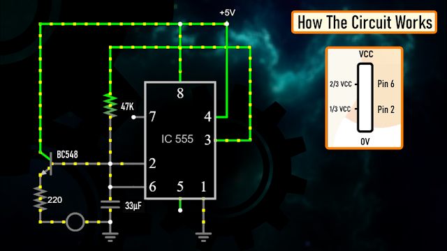
Circuit Diagram
The heart of this circuit is the 555 timer IC.
Pin No.1 of the IC is connected to GND.
By connecting Pin 2 and 6 of the 555 timer IC, we put the IC in astable mode. In astable mode, the 555 timer IC acts as an oscillator (re-triggering itself) generating square waves [PWM Signals] from the output Pin no. 3.
3 other components connect to this junction.
1st one is the 33µF capacitor. The positive pin of the capacitor connects to the junction and the negative pin is connected to the GND.
2nd one is the 47KΩ resistor. One of its legs connects to the junction and the other leg connects to the Output pin, Pin No.3 of the IC.
3rd one is the Base of the BC548 NPN transistor. The collector of the transistor along with Pin 8 and 4 of the IC connects to the +ve terminal. of the battery. The LED along with its current limiting resistor is connected to the Emitter of the transistor.
That's it as simple as that.
Alright, now I am going to demonstrate how this circuit works with the help of an animation.
How The Circuit Works
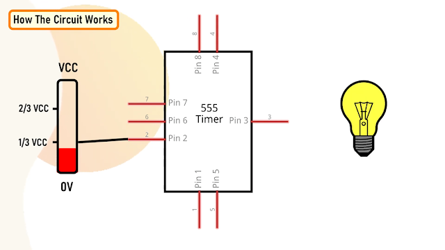
When Pin 2 of the IC detects voltage LESS than 1/3rd of the supply voltage, it turns ON the output on Pin 3.
And, when Pin 6 detects voltage MORE than 2/3rds of the supply voltage, it turns OFF the output.
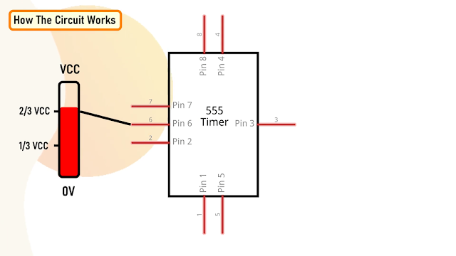
This is how the trigger pin (Pin2) and the
threshold pin (Pin6) of the 555 timer IC sense voltages and controls the output at Pin 3.
The Capacitor attached to the circuit will be in a discharged state immediately after firing up the circuit.
So, the voltage at Pin 2 will be 0v which is less than 1/3rds of the supply voltage, this will turn ON the output on Pin 3.
Since Pin 3 is looped back to Pin 2, it will start charging the Capacitor via the 47KΩ resistor.
At the same time the base current of the transistor also increases causing the LED to slowly "fade-in".
Once the voltage across the capacitor crosses 2/3rds of the supply voltage, Pin 6 turns OFF the output.
This causes the capacitor to slowly discharge causing the base current to fall and hence the LED starts "fading-out".

Once the voltage across the capacitor falls below 1/3rd of the supply voltage, Pin 2 turns ON the output, and the above cycle continues.
You can hook up a multimeter to the circuit to measure the charging and discharging of the capacitor.
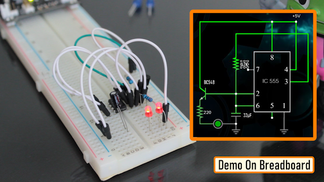
Breadboard Demo
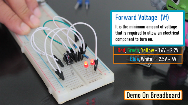
So, here is a quick demo on a breadboard.
In the current setup I have a 33µF Capacitor and a Blue LED on the breadboard.
Replacing the 33µF Capacitor with a 100µF Capacitor makes the LED fade in-and-out slower as the 100µF capacitor charges and discharges slower than 33µF Capacitor.
Also by replacing the "Blue LED" with a "Red LED", we can make the LED to stay "on" longer than the blue one with the same value of capacitor. This is because the "Forward Voltage" (Vf) of the Blue LED is higher than that of the Red LED.
"Forward voltage" is the minimum amount of voltage that is required to allow an electrical component to turn on.
The red, green and yellow LEDs have relatively "low" forward voltage ranging from 1.6-2.2V and hence stays on longer when the capacitor slowly charges or discharged. However, blue and white LEDs starts conducting from 2.5-4V and hence, when the discharging capacitor's voltage hits the threshold the LED turns off faster than the other colors. I have provided a link to how the forward voltage works in the description below.
If you connect few LEDs in series, the forward voltage adds up and hence it will require more voltage to turn on the LEDs.

You need to add a current limiting resistor between the emitter of the transistor and the LED to avoid an internal short-circuiting inside the led.
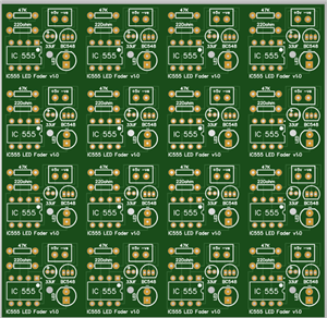
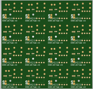
The Board
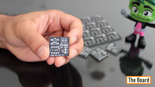
To make it easy for you guys, I have created this tiny little "555 LED Fader Module". After assembling the components, you just need to power this module by providing a voltage between 5v to 15v to fade the LED.
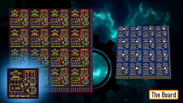
So, this is how my board looks like in 2D and 3D. There are 16 breakout boards in this 100cm x 100cm assembly. You can download the gerber file from the link provided in the description below and order it from PCBWay.
Soldering
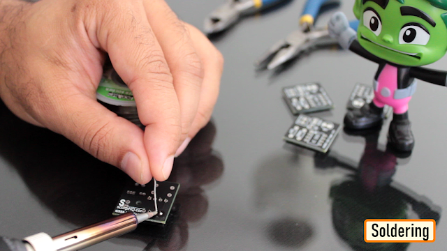
Let me quickly show you guys how to assemble the components to this custom made board.
Let's start by soldering the IC Base to the board.
Then let's solder the two resistors to the board. Next, lets solder the capacitor followed by the transistor to the board. Then, lets solder a blue LED to the board.
Once done, let's insert the 555 timer IC to the IC base.
To conclude the setup, I soldered 2 x Female pin headers to the board. You can either solder a pair of female pin-header or male pin-header or solder a pair of wires directly to the board to power this module.

Cool, so this is how my module finally looks like.
You can install female pin-headers in-place of the LED or Capacitor if you plan to use this as a development/testing board instead of a module.

Assembling the Trophy

Alright, it's time for me to put everything together! First, let’s glue the plastic cutout to the back of the front bit.

Once that’s done, I added aluminum foil to the back section to boost the reflection inside the box.

Next, let's solder a wire from the breakout board to the USB-C charging port. Then, let's attach all the five LEDs to the circuit board, including a red LED on the 5V input for the dragon’s eye. Once everything’s in place, I carefully hot-glue each LED to the back of the unit.

Once that was all set, I superglued the top part to the bottom part. Finally, I mounted the whole assembly on a wooden base to complete the setup.
Final Demo

So, this is how my final setup looks like.
Feel free to leave a feedback or suggestion in the comments if you see any room for improvement.
Thanks
Thanks again for checking my post. I hope it helps you.
If you want to support me subscribe to my YouTube Channel: https://www.youtube.com/@CrazyCoupleDIY
Video: https://youtu.be/Q4CRfxDFBEk
Full Blog Post: https://diy-projects4u.blogspot.com/2025/06/3dBreathing555.html
References
GitHub: https://github.com/tarantula3/-3D-Printed-Breathing-IC555-LED-Trophy-
Gerber: https://github.com/tarantula3/-3D-Printed-Breathing-IC555-LED-Trophy-
STL: https://github.com/tarantula3/-3D-Printed-Breathing-IC555-LED-Trophy-
What Is Forward Voltage: https://42electronics.com/blogs/learn-more/what-is-forward-voltage
LED Fader Using 555 Timer IC: https://youtu.be/30wGujPnupw
Support My Work:
BTC: 1Hrr83W2zu2hmDcmYqZMhgPQ71oLj5b7v5
LTC: LPh69qxUqaHKYuFPJVJsNQjpBHWK7hZ9TZ
DOGE: DEU2Wz3TK95119HMNZv2kpU7PkWbGNs9K3
ETH: 0xD64fb51C74E0206cB6702aB922C765c68B97dCD4
BAT: 0x9D9E77cA360b53cD89cc01dC37A5314C0113FFc3
LBC: bZ8ANEJFsd2MNFfpoxBhtFNPboh7PmD7M2
COS: bnb136ns6lfw4zs5hg4n85vdthaad7hq5m4gtkgf23 Memo: 572187879
BNB: 0xD64fb51C74E0206cB6702aB922C765c68B97dCD4
MATIC: 0xD64fb51C74E0206cB6702aB922C765c68B97dCD4
Thanks, ca again in my next tutorial.
3D Printed Breathing IC555 LED Trophy
*PCBWay community is a sharing platform. We are not responsible for any design issues and parameter issues (board thickness, surface finish, etc.) you choose.


Raspberry Pi 5 7 Inch Touch Screen IPS 1024x600 HD LCD HDMI-compatible Display for RPI 4B 3B+ OPI 5 AIDA64 PC Secondary Screen(Without Speaker)
BUY NOW


- Comments(0)
- Likes(2)
More by Ashish Adhikari
-
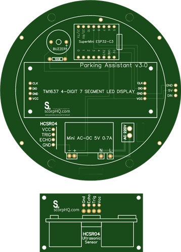 Arduino Parking Assistant V3
The ESP32-C3 Based Parking Assistant is an advanced parking sensor system that utilizes the ESP32-C3...
Arduino Parking Assistant V3
The ESP32-C3 Based Parking Assistant is an advanced parking sensor system that utilizes the ESP32-C3...
-
 100 LED Chaser Circuit Using IC555 and CD4017
A Chaser Circuit consists of a clocked IC or other electronic unit like an Arduino that drives an ar...
100 LED Chaser Circuit Using IC555 and CD4017
A Chaser Circuit consists of a clocked IC or other electronic unit like an Arduino that drives an ar...
-
 Cute Medusa 3D Printed Humidifier
Humidifiers add moisture to the air. They can help people with dry skin, allergies, and respiratory ...
Cute Medusa 3D Printed Humidifier
Humidifiers add moisture to the air. They can help people with dry skin, allergies, and respiratory ...
-
 4x4x4 PCB LED CUBE
Note from PCBWay: This project includes two PCBs, if both need to be produced, please inform your sa...
4x4x4 PCB LED CUBE
Note from PCBWay: This project includes two PCBs, if both need to be produced, please inform your sa...
-
 Getting Started With Raspberry Pi Pico
Couple of months ago, I bought a "Raspberry Pi Pico" to get some hands-on experience of it and to cr...
Getting Started With Raspberry Pi Pico
Couple of months ago, I bought a "Raspberry Pi Pico" to get some hands-on experience of it and to cr...
-
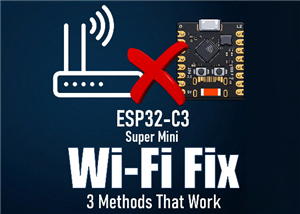 ESP32 C3 Super Mini WiFi Fix - 3 Methods That Work
Hi everyone! I’ve recently started working with a tiny, super affordable microcontroller board calle...
ESP32 C3 Super Mini WiFi Fix - 3 Methods That Work
Hi everyone! I’ve recently started working with a tiny, super affordable microcontroller board calle...
-
 Programmable RGB Thermometer
Summer has been relentless this year. My passion for Bitcoin mining took a major hit due to the imme...
Programmable RGB Thermometer
Summer has been relentless this year. My passion for Bitcoin mining took a major hit due to the imme...
-
 All About PC817 Optocoupler
An Optocoupler also known as Photocoupler or Optical Isolator is a component that transfers electric...
All About PC817 Optocoupler
An Optocoupler also known as Photocoupler or Optical Isolator is a component that transfers electric...
-
 Make Your Own 3D Printed Diwali Diyas at Home
Diyas are the heart of major Indian festivals, most notably Diwali, the "Festival of Lights." Lighti...
Make Your Own 3D Printed Diwali Diyas at Home
Diyas are the heart of major Indian festivals, most notably Diwali, the "Festival of Lights." Lighti...
-
 Arduino Based 3D Printed Color Adjustable Minecraft Lantern
For this Halloween, I'm fusing the creative blocky world of Minecraft with the spooky glow of the co...
Arduino Based 3D Printed Color Adjustable Minecraft Lantern
For this Halloween, I'm fusing the creative blocky world of Minecraft with the spooky glow of the co...
-
 3D Printed Breathing IC555 LED Trophy
This project features a custom 3D-printed 'Mortal Kombat' trophy shell paired with a basic NE555 tim...
3D Printed Breathing IC555 LED Trophy
This project features a custom 3D-printed 'Mortal Kombat' trophy shell paired with a basic NE555 tim...
-
 Destiny Internet Ghost - Internet Notifier
The Internet has changed the way we live our lives. From communication, education, banking, entertai...
Destiny Internet Ghost - Internet Notifier
The Internet has changed the way we live our lives. From communication, education, banking, entertai...
-
 Liquid level indicator Using ULN2003
A water level indicator detects and indicates the level of water in an overhead tank and relays the ...
Liquid level indicator Using ULN2003
A water level indicator detects and indicates the level of water in an overhead tank and relays the ...
-
 All About IC UNL2003
The UNL2003 IC contains 7 High Voltage, High Current NPN Darlington Transistor Arrays each rated at ...
All About IC UNL2003
The UNL2003 IC contains 7 High Voltage, High Current NPN Darlington Transistor Arrays each rated at ...
-
 NodeMCU Based: 3D Printed Indoor Gauge Thermometer
Had some time this weekend and a desire to create something new and interesting, so went ahead and c...
NodeMCU Based: 3D Printed Indoor Gauge Thermometer
Had some time this weekend and a desire to create something new and interesting, so went ahead and c...
-
 Rechargeable Gothic Lantern
A Gothic Lantern is a captivating piece of lighting that brings the allure of the Victorian Era into...
Rechargeable Gothic Lantern
A Gothic Lantern is a captivating piece of lighting that brings the allure of the Victorian Era into...
-
 555 Adjustable Delay On Off Timer Circuit
The 555 timer IC is an integrated circuit (IC) that is used in a variety of timer, delay, pulse gene...
555 Adjustable Delay On Off Timer Circuit
The 555 timer IC is an integrated circuit (IC) that is used in a variety of timer, delay, pulse gene...
-
 3D Printed Arduino Halloween Décor
When the full moon is shining and the wolves are howling, it's time for Halloween's spooky spectacle...
3D Printed Arduino Halloween Décor
When the full moon is shining and the wolves are howling, it's time for Halloween's spooky spectacle...
-
Programmable Mist Maker - XIAO / QT PY Extension
217 0 0 -
RadioHAT - Raspberry Pi radio development platform
244 0 1 -
-
-
-
-
ARPS-2 – Arduino-Compatible Robot Project Shield for Arduino UNO
2795 0 5 -
A Compact Charging Breakout Board For Waveshare ESP32-C3
3299 3 8 -
AI-driven LoRa & LLM-enabled Kiosk & Food Delivery System
3575 2 2


