



|
|
ESP32-C3 SuperMini_TH |
x 1 | |
|
|
CD4017i-CORE/无锡中微爱芯
|
x 1 |

|
arduino IDEArduino
|
DIY LED Roulette Wheel | ESP32 C3 Project
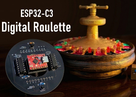
Hi everyone, today I am going to show you how I made a "Digital Roulette Wheel" by combining ESP32-C3 Super Mini Microcontroller with the classic CD4017 CMOS decade counters.
When the button is pressed, the ESP32 sends "clock pulses" to the CD4017 IC, causing the LEDs to cycle. Releasing the button triggers a realistic slowing down effect until it stops on a random result and reports the final position using the Serial Monitor or via Wi-Fi.
Trust me, there's a lot going on with this project hardware design, Arduino coding, PHP, databases, 3D design and printing, and more.
Video: https://youtu.be/5jVFR7KSNmg
Full Blog Post: https://diyfactory007.blogspot.com/2026/05/Roulette.html
Components Required

For this project we need:
🔗 1 x ESP32-C3 Super Mini Plus Microcontroller: https://s.click.aliexpress.com/e/_c2zUTvyj
🔗 2 x CD4017 CMOS Decade Counters: https://s.click.aliexpress.com/e/_c33qzzRt
🔗 2 x 2N2222 NPN Transistors: https://s.click.aliexpress.com/e/_c4OwNvnZ
🔗 3 x 220Ω Resistors: https://s.click.aliexpress.com/e/_c41SucJd
🔗 1 x 10kΩ Resistor: https://s.click.aliexpress.com/e/_c41SucJd
🔗 1 x Push Button Switch: https://s.click.aliexpress.com/e/_c3cfuN6J
🔗 1 x SPDT Switch: https://s.click.aliexpress.com/e/_c4FRHRaX
🔗 18 x 5mm Red LEDs: https://s.click.aliexpress.com/e/_c2RpNzh9
🔗 2 x 5mm Green LEDs: https://s.click.aliexpress.com/e/_c2RpNzh9
🔗 1 x 3mm Blue LED: https://s.click.aliexpress.com/e/_c306Pzbh
🔗 1 x 10mfd Capacitor (optional)
🔗 1 x LiPo Battery: https://s.click.aliexpress.com/e/_c4okFfef
🔗 1 x Battery Charging Module (optional): https://s.click.aliexpress.com/e/_c3EJLcZh
🔗 1 x Battery Level Indicator: https://s.click.aliexpress.com/e/_c4KGEDh5
And a 3D Printer to print the enclosure
Circuit Diagram

The wiring of this project is really simple!
* Connect Pin-8 of the ESP32 to the Reset pin (Pin 15) of IC#1.
* Connect Pin-10 of the ESP32 to the Clock pin (Pin 14) of IC#1.
* Connect Pin-9 of the ESP32 to the push-button switch with a pull-up resistor.
* Connect Pin-0 of the ESP32 to the Wi-Fi Indicator LED with a current limiting resistor.
For the rest of the wiring, check out the circuit diagram on screen.

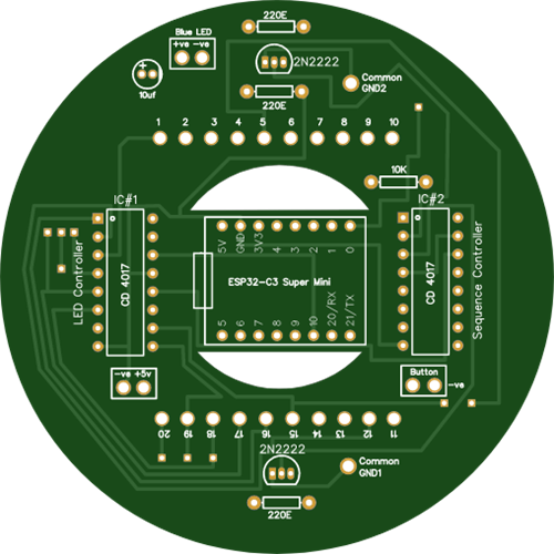
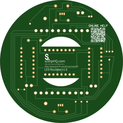
To make things even easier, I’ve designed a custom PCB for you. You can grab the Gerber file from the description below and get the board fabricated from [PCBWay.com](https://PCBWay.com).
Core Functionality

I originally built this LED roulette project using a 555 timer IC and a couple of CD4017 CMOS decade counters. The 555 timer functions as a clock oscillator, generating a signal that drives the 4017 decade counter. The output from PIN-3 of the IC555 is fed into PIN-14 of the IC4017. Each time the IC4017 receives a pulse, it increments the count and activates the next output pin (Q0 to Q9), creating a shifting LED effect.
To know more about the ICs please check out my tutorial no. 26 "555 Pulse Generator Module, How it Works", the link is in the description below.
The main drawback of this initial design is that I had to handle the counting manually. I wanted a system where the numbers are added automatically and the winner is determined by the system itself. My goal isn't to build a gambling wheel, but rather a simple roulette game that I can enjoy playing with my son.
To achieve that, the ESP32-C3 Super Mini turned out to be the perfect choice. It is compact and comes with built-in Wi-Fi capability.

So, instead of using the 555 timer IC, I switched to the ESP32-C3 board to generate "clock pulses" for one of the CD4017 ICs. When the button is pressed, the pulses become faster and faster. The light races around the circle, creating the sensation of a "spin." When the button is released, the spin doesn't stop immediately. Instead, it gradually increases the time between the pulses, making the lights slow down progressively - just like a real wheel coasting to a stop.
Once it slows down enough, it stops completely and reports the final LED position via the Serial Monitor or Wi-Fi. The result is then saved into MySQL database and is visualized using PHP.
The Code

Now let’s take a look at the logic powering the entire show.
As mentioned earlier the system relies on lot of components, Arduino code, PHP, MySQL database and more. My GitHub repository contains two versions of the code: one with a server and the other without. If you don’t need the results saved on a server, you can simply upload the "Code_No_Wi-Fi" to your ESP32 board.
However, for this tutorial, I’ll demonstrate the full functionality of the setup.
Now, let's review the codes one by one.

In the Arduino code, you'll need to enter your network's SSID and password, as well as set the server IP and URL to match the directory where your PHP files will reside.
No other parts of the code need to be modified unless you want to add new features to the existing functionality.
When you power on the roulette, the ESP32 first attempts to connect to the server via Wi-Fi. Once the connection is established, players can begin the game. Pressing the button speeds up the LED sequence by reducing the delay, while releasing the button slows it down by increasing the delay - until it passes a stop threshold. This creates a natural freewheeling effect before the sequence comes to a complete stop.
Once the LED wheel stops, the ESP32-C3 sends the winning position to a remote server. This process continues as long as players keep playing.

In addition to the code, I’ve included a "MySQL_DB.sql" file that need to be imported into your MySQL server.
To do this, open phpMyAdmin, go to the "Import" tab, click "Choose File" button, and select the "MySQL_DB.sql" file. Then click the "Go" button to import the tables. To verify the import was successful, click on the table names and check that the table structures appear correctly.

To set up the web server, we need to make some changes to the downloaded PHP files from my GitHub repository. Open "Connection.php" and update the hostname, user name, password and database name in the file. Then, drag and drop the files into a directory on your web server.
To verify that everything is working correctly, open the "Player_Results_Display.php" file in a web browser and confirm that the leaderboard appears correctly.

Breadboard Demo

Now that the hardware logic is ready and the server is set up, we can perform a quick test on a breadboard to verify the system’s functionality.
Let’s go ahead and press the button to see if the serial monitor registers the press. As we can see an HTTP 200 code is displayed on the serial monitor, indicating successful communication with the server. On the Leaderboard page, we can confirm that the server has recorded the button press. The webpage auto-refreshes every 5 seconds, displaying the latest scores from both players in real time.
The page includes side-by-side scorecards for "Player 1" and "Player 2", showing live scores, wins, losses, ties, and total games played by each player.
When you click the "New Game" button, the page resets, and the system updates the player's win, loss, or tie count based on the current score.
3D Printing

Using Microsoft 3D Builder, I designed the 3D model of this project.
The design consists of three parts:
- The top section, which holds all the LEDs,
- The bottom section, which contains all the electronic components and
- A small block which houses a blue Wi-Fi indicator LED, a battery charging module, an SPDT on/off switch, plus holes for the antenna cable and the push button switch.
I sliced the model in Bambu Studio and printed it out using my new Bambu A1 3D printer. For those seeking ultra-fine, industrial-grade 3D printing, I recommend having the STLs printed from PCBWay.com.
Finally, using Acrylic colors I painted the body of the project. The gold finish really elevated the print's appearance. After the paint dried, I installed all the LEDs into the top section and soldered their negative legs together in "pairs of ten".
Soldering

Now, let’s begin assembling all the electronic components. First, take a moment to inspect the quality of the fabricated PCB. I’ve been using PCBWay for nearly six years now, and I absolutely love the final product they deliver.
Lets start by soldering all the resistances to the board followed by all the transistors.
Because I take extra care of my ICs and microcontrollers, I never solder them directly to the board. For ICs, I always use IC base and if a base is not available, I use female pin headers. This avoids direct soldering and makes replacement easy. One by one, I soldered all the components to the PCB.

To power the board, we need to integrate the charging module and some additional components. I began by installing the SPDT Switch followed by the blue Wi-Fi indicator LED. Then I super-glued the world smallest battery charging module to the block and secured it using this small white block. Finally I superglued the charging indicator as per the onscreen circuit diagram.

The remaining two holes accommodate the antenna and the push-button switch. Finally, once all components were in place, I glued the plastic block into the groove at the bottom of the base.
This is how the board looks like after I finished soldering all the wires that will connect to the LEDs. For LEDs 1 through 10, use Common GND2 and for LEDs 11 through 20, use Common GND1. 
When soldering the LEDs to the board, be sure to solder them in the correct order to avoid mismatching the physical LED numbers with what the code sends to the server. Follow the onscreen instructions for the correct order. If you accidentally solder the LEDs incorrectly you can modify the array in the Arduino code to accommodate the change.
In my setup, I’m powering everything with a 3.7V rechargeable battery. However, if you prefer, you can solder either a 220V-to-5V step-down converter or a USB cable to the +5V and -VE holes on the board.

Once everything is in place, all that’s left is to glue the bottom bit to the top bit. That’s it, as simple as that.
Final Demo

With the hardware ready, its time to have some fun! Power on the unit and wait for the blue LED to light up. When it lights up, it confirms the Wi-Fi link to the server. Press the push-button to begin the LED chase. Your score can be viewed on any device (PC or mobile) connected to the same network.
In short, this setup turns a simple button-and-LED system into a realistic-feeling game by adding "momentum" to the movement.
Thanks
Thanks again for checking my post. I hope it helps you.
If you want to support me subscribe to my YouTube Channel: https://www.youtube.com/user/tarantula3
Video: https://youtu.be/5jVFR7KSNmg
Full Blog Post: https://diyfactory007.blogspot.com/2026/05/Roulette.html
References
GitHub: https://github.com/tarantula3/ESP32_Roulette
Gerber: Download
STL: https://github.com/tarantula3/ESP32_Roulette
DIY 555 Pulse Generator Module: https://youtu.be/bMAnipPOjFo
Support My Work
BTC: 1Hrr83W2zu2hmDcmYqZMhgPQ71oLj5b7v5
LTC: LPh69qxUqaHKYuFPJVJsNQjpBHWK7hZ9TZ
DOGE: DEU2Wz3TK95119HMNZv2kpU7PkWbGNs9K3
ETH: 0xD64fb51C74E0206cB6702aB922C765c68B97dCD4
BAT: 0x9D9E77cA360b53cD89cc01dC37A5314C0113FFc3
BNB: 0xD64fb51C74E0206cB6702aB922C765c68B97dCD4
POL: 0xD64fb51C74E0206cB6702aB922C765c68B97dCD4
LBC: bZ8ANEJFsd2MNFfpoxBhtFNPboh7PmD7M2
COS: bnb136ns6lfw4zs5hg4n85vdthaad7hq5m4gtkgf23 Memo: 572187879
Thanks, ca again in my next tutorial.
DIY LED Roulette Wheel | ESP32 C3 Project
Project images are for reference only. Actual production is based on the manufacturing files on the project page.
Please review the designer's notes (e.g., PCB thickness) and select the appropriate options.
PCBWay is not responsible
for issues caused by unsuitable parameter selections.
For more important ordering information, please refer to
Read More









Raspberry Pi 5 7 Inch Touch Screen IPS 1024x600 HD LCD HDMI-compatible Display for RPI 4B 3B+ OPI 5 AIDA64 PC Secondary Screen(Without Speaker)
BUY NOW


- Comments(0)
- Likes(0)
More by Ashish Adhikari
-
 Arduino Parking Assistant V3
The ESP32-C3 Based Parking Assistant is an advanced parking sensor system that utilizes the ESP32-C3...
Arduino Parking Assistant V3
The ESP32-C3 Based Parking Assistant is an advanced parking sensor system that utilizes the ESP32-C3...
-
 100 LED Chaser Circuit Using IC555 and CD4017
A Chaser Circuit consists of a clocked IC or other electronic unit like an Arduino that drives an ar...
100 LED Chaser Circuit Using IC555 and CD4017
A Chaser Circuit consists of a clocked IC or other electronic unit like an Arduino that drives an ar...
-
 Cute Medusa 3D Printed Humidifier
Humidifiers add moisture to the air. They can help people with dry skin, allergies, and respiratory ...
Cute Medusa 3D Printed Humidifier
Humidifiers add moisture to the air. They can help people with dry skin, allergies, and respiratory ...
-
 4x4x4 PCB LED CUBE
Note from PCBWay: This project includes two PCBs, if both need to be produced, please inform your sa...
4x4x4 PCB LED CUBE
Note from PCBWay: This project includes two PCBs, if both need to be produced, please inform your sa...
-
 Getting Started With Raspberry Pi Pico
Couple of months ago, I bought a "Raspberry Pi Pico" to get some hands-on experience of it and to cr...
Getting Started With Raspberry Pi Pico
Couple of months ago, I bought a "Raspberry Pi Pico" to get some hands-on experience of it and to cr...
-
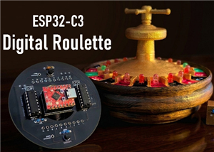 DIY LED Roulette Wheel | ESP32 C3 Project
Hi everyone, today I am going to show you how I made a "Digital Roulette Wheel" by combining ESP32-C...
DIY LED Roulette Wheel | ESP32 C3 Project
Hi everyone, today I am going to show you how I made a "Digital Roulette Wheel" by combining ESP32-C...
-
 ESP32 C3 Super Mini WiFi Fix - 3 Methods That Work
Hi everyone! I’ve recently started working with a tiny, super affordable microcontroller board calle...
ESP32 C3 Super Mini WiFi Fix - 3 Methods That Work
Hi everyone! I’ve recently started working with a tiny, super affordable microcontroller board calle...
-
 Programmable RGB Thermometer
Summer has been relentless this year. My passion for Bitcoin mining took a major hit due to the imme...
Programmable RGB Thermometer
Summer has been relentless this year. My passion for Bitcoin mining took a major hit due to the imme...
-
 All About PC817 Optocoupler
An Optocoupler also known as Photocoupler or Optical Isolator is a component that transfers electric...
All About PC817 Optocoupler
An Optocoupler also known as Photocoupler or Optical Isolator is a component that transfers electric...
-
 Make Your Own 3D Printed Diwali Diyas at Home
Diyas are the heart of major Indian festivals, most notably Diwali, the "Festival of Lights." Lighti...
Make Your Own 3D Printed Diwali Diyas at Home
Diyas are the heart of major Indian festivals, most notably Diwali, the "Festival of Lights." Lighti...
-
 Arduino Based 3D Printed Color Adjustable Minecraft Lantern
For this Halloween, I'm fusing the creative blocky world of Minecraft with the spooky glow of the co...
Arduino Based 3D Printed Color Adjustable Minecraft Lantern
For this Halloween, I'm fusing the creative blocky world of Minecraft with the spooky glow of the co...
-
 3D Printed Breathing IC555 LED Trophy
This project features a custom 3D-printed 'Mortal Kombat' trophy shell paired with a basic NE555 tim...
3D Printed Breathing IC555 LED Trophy
This project features a custom 3D-printed 'Mortal Kombat' trophy shell paired with a basic NE555 tim...
-
 Destiny Internet Ghost - Internet Notifier
The Internet has changed the way we live our lives. From communication, education, banking, entertai...
Destiny Internet Ghost - Internet Notifier
The Internet has changed the way we live our lives. From communication, education, banking, entertai...
-
 Liquid level indicator Using ULN2003
A water level indicator detects and indicates the level of water in an overhead tank and relays the ...
Liquid level indicator Using ULN2003
A water level indicator detects and indicates the level of water in an overhead tank and relays the ...
-
 All About IC UNL2003
The UNL2003 IC contains 7 High Voltage, High Current NPN Darlington Transistor Arrays each rated at ...
All About IC UNL2003
The UNL2003 IC contains 7 High Voltage, High Current NPN Darlington Transistor Arrays each rated at ...
-
 NodeMCU Based: 3D Printed Indoor Gauge Thermometer
Had some time this weekend and a desire to create something new and interesting, so went ahead and c...
NodeMCU Based: 3D Printed Indoor Gauge Thermometer
Had some time this weekend and a desire to create something new and interesting, so went ahead and c...
-
 Rechargeable Gothic Lantern
A Gothic Lantern is a captivating piece of lighting that brings the allure of the Victorian Era into...
Rechargeable Gothic Lantern
A Gothic Lantern is a captivating piece of lighting that brings the allure of the Victorian Era into...
-
 555 Adjustable Delay On Off Timer Circuit
The 555 timer IC is an integrated circuit (IC) that is used in a variety of timer, delay, pulse gene...
555 Adjustable Delay On Off Timer Circuit
The 555 timer IC is an integrated circuit (IC) that is used in a variety of timer, delay, pulse gene...
-
SmallOLED - Live PC Stats, Animated Clocks & Audio Visualizer
616 0 3 -
"Talking Multimeter": Arduino-Based Speech Add-on for Multimeters with SCPI Protocol
348 0 1 -
Programmable Mist Maker - XIAO / QT PY Extension
2788 2 3 -
RadioHAT - Raspberry Pi radio development platform
2391 0 4 -
-
-
-
ARPS-2 – Arduino-Compatible Robot Project Shield for Arduino UNO
4486 0 6


















