


|
|
555 Timer IC |
x 1 | |
|
|
Push Button Switch |
x 1 | |
|
|
LED |
x 2 | |
|
|
220Ohm |
x 1 | |
|
|
1K |
x 1 | |
|
|
470uF |
x 1 |
555 Adjustable Delay On Off Timer Circuit
The 555 timer IC is an integrated circuit (IC) that is used in a variety of timer, delay, pulse generator and oscillator circuits.
In this tutorial, I am going to show you guys how to make an "Adjustable Delay Timer Circuit" using the 555 timer IC. This circuit can automatically turn on/off any circuit after a fixed duration. This timer circuit is useful when you need to power On/Off any AC Appliances after a pre-defined duration. For example, you can use this circuit to automatically turn off a mobile charger after a certain period of time to avoid over charging, or you can turn on/off a light bulb after a certain period.
The time delay of this circuit can be adjusted by using various combinations of resistors and capacitors.
Watch this video for detailed step by step instructions on how to build this circuit and to know how this circuit works.
Components Required

For this tutorial we need:A 555 Timer IC
A Push Button Switch
A Red And A Green LED
2 x 220Ohm Current Limiting Resistors
1 x 10K Resistor
A Breadboard and Few Breadboard Connectors
A 5V Power Supply
A 470uF Capacitor
And Few Combinations Of Resistors Or A Potentiometer
555 Timer IC In Monostable Mode

Lets start by putting all the components together and lets understand how the circuit works.
In the first example, I am going to show you guys the "on-off timer circuit" with a fixed timing Resistor and Capacitor.
The heart of this circuit is the 555 timer IC.
Pin No.1 of the IC is connected to GND.
By connecting Pin 6 and 7 of the 555 timer IC, we put the IC in "Monostable Mode". In Monostable Mode, the output of the IC is stable in "One State", and it will always return to this state after a certain period of time when it gets pushed out of that state.
The output at Pin 3 of the 555 Timer IC in monostable mode is generally LOW - indicated by the green LED. When you trigger the circuit using the push button switch, the output goes HIGH - indicated by the red LED, for a certain period of time before it goes back to its LOW state.
The time the circuit stays HIGH is decided by the value of a resistor R1 and a capacitor C1. The higher the values, the longer it stays HIGH (On).
To adjust the timer duration "on-the-fly", the timing Resistor R1 can be replaced by a Potentiometer. By changing the value of the resistance of the potentiometer we can either increase or decrease the duration of the timer.
Logic Using Circuit Simulation

Alright, now I am going to explain how this circuit works with the help of an animation.
When Pin 2 of the IC detects voltage LESS than 1/3rd of the supply voltage, it turns ON the output on Pin3.
And, when Pin6 detects voltage MORE than 2/3rds of the supply voltage, it turns OFF the output.
Whenever the output of the IC is in OFF state, the Discharge Pin (Pin7) acts as ground, as it is internally grounded.
This is how the trigger pin (Pin2) and the threshold pin (Pin6) of the 555 timer IC sense voltages and controls the output at Pin3.
When we power on the circuit, the output is in OFF state. Hence, the discharge pin (Pin7) will be internally grounded discharging the capacitor.
Pressing the push button switch activates the delay timer and the following sequence starts:
Trigger Pin (Pin2) gets grounded
Since this applied voltage at Pin2 (0V) is less than 1/3rd of the supply voltage (5V), the output at Pin3 turns ON
And at the same time, the Discharge Pin (Pin7) disconnects internally from 0V
This causes the capacitor to charge via the resistor or potentiometer
Now, the voltage across Pin6 starts increasing
As soon as the capacitor charges to 2/3rds of the supply voltage, Pin6 turns OFF the output
When the output turns OFF, Pin7 gets internally grounded discharging the capacitor.
The above steps are repeated each time you push the push button switch.
The time period for which the capacitor charges from 0V to 2/3rds of supply voltage is the "delay time".
Calculations
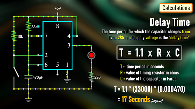
A discussed earlier, the time period for which the capacitor charges from 0V to 2/3rds of supply voltage is the "delay time".
We can calculate this time using the formula: T = 1.1 * R * C
Where T is the time period in seconds, R is the value of timing resistor in ohms and C is the value of the capacitor in Farad.
In the previous example we used a 33K resistor and 470uF capacitor which gives us a delay period of:
T = 1.1 * (33000) * (0.000470) = 17 seconds.
The Board

To make things easy, I designed a PCB for this setup.
So, this is how my PCB looks like in 2D and 3D.
You can either add a resistance or a potentiometer to the board to control the delay time.
I have created 2 versions of this board:
V1: Without A Relay Module
V2: With A Relay Module

Using the board with the relay module, you can control other DC Circuits or AC Appliances.
For a quick reference, I added the delay period calculator on the board.
Soldering

Alright, now, lets solder the components to the board.
In this setup, I am going to solder a potentiometer to the board and hence I will leave the resistor bit as is.
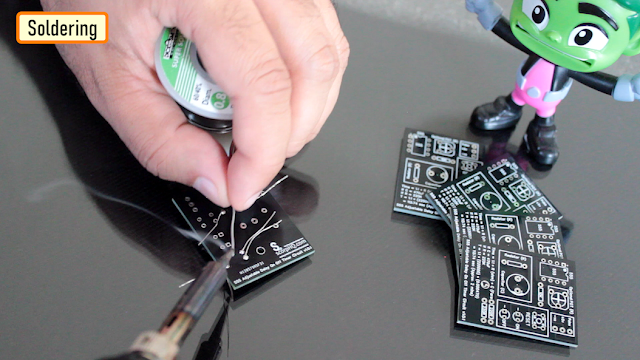
So, lets start by soldering all the resistances to the board.
Then, lets solder the LEDs to the board followed by the Push Button Switch.
After that, lets solder the IC base and the capacitor to the board.
As discussed earlier, instead of the resistor I am soldering a Potentiometer to the board.
To finalize the setup, I am soldering few male pin headers to the board, that's it all done.
The 2nd version of the board with the relay module looks like this.
Demo

For the demo purpose, I am going to use the board that has the relay module on it.
Using this board, I can demo both the operation of the relay and the LEDs.
Lets set the resistance of the potentiometer to a desired value and then lets do the quick math to see how long this circuit will stay on.
Alright, now that we have all the values, lets start the timer on my mobile and press the push button switch both at the same time.............
Bingo, mission accomplished.
You can use the relay in either NC or NO state in your project.

Uses

This Delay Timer Circuit can be used as a:
Timer for any robotics project
Turning off mobile chargers to prevent overcharging
Turning On/Off lights automatically after a set duration
In Auto power On/Off circuits using Relays and more..
The possibilities are endless..
Thanks
Thanks again for checking my post. I hope it helps you.
If you want to support me subscribe to my YouTube Channel: https://www.youtube.com/user/tarantula3
PCBWay 6th Project Design Contest: https://www.pcbway.com/activity/6th-project-design-contest.html
Video: https://youtu.be/AB8XjBGvlPY
Full Blog Post: https://diyfactory007.blogspot.com/2023/11/555-Adjustable-Delay-Timer.html
DIY - Relay Module: https://youtu.be/3n69b4sdDjk
Schema: https://github.com/tarantula3/555-Adjustable-Delay-Timer/blob/main/8.png
Circuit: https://github.com/tarantula3/555-Adjustable-Delay-Timer
Gerber Files: https://github.com/tarantula3/555-Adjustable-Delay-Timer
Support My Work
BTC: 1Hrr83W2zu2hmDcmYqZMhgPQ71oLj5b7v5
LTC: LPh69qxUqaHKYuFPJVJsNQjpBHWK7hZ9TZ
DOGE: DEU2Wz3TK95119HMNZv2kpU7PkWbGNs9K3
ETH: 0xD64fb51C74E0206cB6702aB922C765c68B97dCD4
BAT: 0x9D9E77cA360b53cD89cc01dC37A5314C0113FFc3
LBC: bZ8ANEJFsd2MNFfpoxBhtFNPboh7PmD7M2
COS: bnb136ns6lfw4zs5hg4n85vdthaad7hq5m4gtkgf23 Memo: 572187879
BNB: 0xD64fb51C74E0206cB6702aB922C765c68B97dCD4
MATIC: 0xD64fb51C74E0206cB6702aB922C765c68B97dCD4
Thanks, ca gain in my next tutorial.
555 Adjustable Delay On Off Timer Circuit
*PCBWay community is a sharing platform. We are not responsible for any design issues and parameter issues (board thickness, surface finish, etc.) you choose.


Raspberry Pi 5 7 Inch Touch Screen IPS 1024x600 HD LCD HDMI-compatible Display for RPI 4B 3B+ OPI 5 AIDA64 PC Secondary Screen(Without Speaker)
BUY NOW


- Comments(0)
- Likes(3)
More by Ashish Adhikari
-
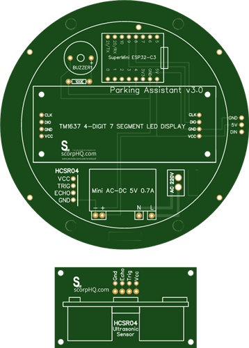 Arduino Parking Assistant V3
The ESP32-C3 Based Parking Assistant is an advanced parking sensor system that utilizes the ESP32-C3...
Arduino Parking Assistant V3
The ESP32-C3 Based Parking Assistant is an advanced parking sensor system that utilizes the ESP32-C3...
-
 100 LED Chaser Circuit Using IC555 and CD4017
A Chaser Circuit consists of a clocked IC or other electronic unit like an Arduino that drives an ar...
100 LED Chaser Circuit Using IC555 and CD4017
A Chaser Circuit consists of a clocked IC or other electronic unit like an Arduino that drives an ar...
-
 Cute Medusa 3D Printed Humidifier
Humidifiers add moisture to the air. They can help people with dry skin, allergies, and respiratory ...
Cute Medusa 3D Printed Humidifier
Humidifiers add moisture to the air. They can help people with dry skin, allergies, and respiratory ...
-
 4x4x4 PCB LED CUBE
Note from PCBWay: This project includes two PCBs, if both need to be produced, please inform your sa...
4x4x4 PCB LED CUBE
Note from PCBWay: This project includes two PCBs, if both need to be produced, please inform your sa...
-
 Getting Started With Raspberry Pi Pico
Couple of months ago, I bought a "Raspberry Pi Pico" to get some hands-on experience of it and to cr...
Getting Started With Raspberry Pi Pico
Couple of months ago, I bought a "Raspberry Pi Pico" to get some hands-on experience of it and to cr...
-
 ESP32 C3 Super Mini WiFi Fix - 3 Methods That Work
Hi everyone! I’ve recently started working with a tiny, super affordable microcontroller board calle...
ESP32 C3 Super Mini WiFi Fix - 3 Methods That Work
Hi everyone! I’ve recently started working with a tiny, super affordable microcontroller board calle...
-
 Programmable RGB Thermometer
Summer has been relentless this year. My passion for Bitcoin mining took a major hit due to the imme...
Programmable RGB Thermometer
Summer has been relentless this year. My passion for Bitcoin mining took a major hit due to the imme...
-
 All About PC817 Optocoupler
An Optocoupler also known as Photocoupler or Optical Isolator is a component that transfers electric...
All About PC817 Optocoupler
An Optocoupler also known as Photocoupler or Optical Isolator is a component that transfers electric...
-
 Make Your Own 3D Printed Diwali Diyas at Home
Diyas are the heart of major Indian festivals, most notably Diwali, the "Festival of Lights." Lighti...
Make Your Own 3D Printed Diwali Diyas at Home
Diyas are the heart of major Indian festivals, most notably Diwali, the "Festival of Lights." Lighti...
-
 Arduino Based 3D Printed Color Adjustable Minecraft Lantern
For this Halloween, I'm fusing the creative blocky world of Minecraft with the spooky glow of the co...
Arduino Based 3D Printed Color Adjustable Minecraft Lantern
For this Halloween, I'm fusing the creative blocky world of Minecraft with the spooky glow of the co...
-
 3D Printed Breathing IC555 LED Trophy
This project features a custom 3D-printed 'Mortal Kombat' trophy shell paired with a basic NE555 tim...
3D Printed Breathing IC555 LED Trophy
This project features a custom 3D-printed 'Mortal Kombat' trophy shell paired with a basic NE555 tim...
-
 Destiny Internet Ghost - Internet Notifier
The Internet has changed the way we live our lives. From communication, education, banking, entertai...
Destiny Internet Ghost - Internet Notifier
The Internet has changed the way we live our lives. From communication, education, banking, entertai...
-
 Liquid level indicator Using ULN2003
A water level indicator detects and indicates the level of water in an overhead tank and relays the ...
Liquid level indicator Using ULN2003
A water level indicator detects and indicates the level of water in an overhead tank and relays the ...
-
 All About IC UNL2003
The UNL2003 IC contains 7 High Voltage, High Current NPN Darlington Transistor Arrays each rated at ...
All About IC UNL2003
The UNL2003 IC contains 7 High Voltage, High Current NPN Darlington Transistor Arrays each rated at ...
-
 NodeMCU Based: 3D Printed Indoor Gauge Thermometer
Had some time this weekend and a desire to create something new and interesting, so went ahead and c...
NodeMCU Based: 3D Printed Indoor Gauge Thermometer
Had some time this weekend and a desire to create something new and interesting, so went ahead and c...
-
 Rechargeable Gothic Lantern
A Gothic Lantern is a captivating piece of lighting that brings the allure of the Victorian Era into...
Rechargeable Gothic Lantern
A Gothic Lantern is a captivating piece of lighting that brings the allure of the Victorian Era into...
-
 555 Adjustable Delay On Off Timer Circuit
The 555 timer IC is an integrated circuit (IC) that is used in a variety of timer, delay, pulse gene...
555 Adjustable Delay On Off Timer Circuit
The 555 timer IC is an integrated circuit (IC) that is used in a variety of timer, delay, pulse gene...
-
 3D Printed Arduino Halloween Décor
When the full moon is shining and the wolves are howling, it's time for Halloween's spooky spectacle...
3D Printed Arduino Halloween Décor
When the full moon is shining and the wolves are howling, it's time for Halloween's spooky spectacle...
-
Programmable Mist Maker - XIAO / QT PY Extension
162 0 0 -
RadioHAT - Raspberry Pi radio development platform
174 0 1 -
-
-
-
-
ARPS-2 – Arduino-Compatible Robot Project Shield for Arduino UNO
2762 0 5 -
A Compact Charging Breakout Board For Waveshare ESP32-C3
3266 3 8 -
AI-driven LoRa & LLM-enabled Kiosk & Food Delivery System
3516 2 2


