


|
KiCad 9.0 |
A new 100MHz differential probe
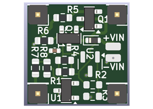
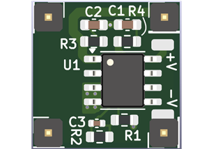
This is a DIY 100MHz version of a new differential probe that was mostly designed by my friend Bud Bennett and tested and verified by me. It can be used with oscilloscopes to look at signals that are not earth ground referenced.
Using the same PCB, you can also build a 10MHz probe and a 1MHz probe. The latter two have really low noise contributions.
There are three BOM's available for the three different versions.
Specifications 100MHz:
- Input impedance: 20MegOhm//1.25pF - differential, 10MegOhm//2.5pF for each terminal to GND.
- Differential Gain = 1/10V/V. Any lower than this and most hobby DSO's cannot resolve a 1V input signal with any clarity.
- Maximum AC Common Mode Voltage (with 50V differential input) = 350VAC
- CMRR > 90dB @ DC, ~60dB @ 1MHz.
- 100MHz: Differential Voltage Range > +/-25V for 240VAC common-mode, +/-25V for 0V common-mode.
- 10MHz: Differential Voltage Range > +/-80V for 240VAC common-mode, +/-80V for 0V common-mode.
- 3dB bandwidth >= 100MHZ (depends on signal amplitude)
- DC offset < 1mV (trimmed)
- Noise: 30mVpp or lower at output.
- Power supply: 5.25V +/- 0.25V. This can be a USB-C PD supply plus a regulator, see the power options.
- Cost: ~$50 not including shipping and handling costs. Not including 3D printed enclosure.
Specifications 10MHz:
- Input impedance: 10MegOhm//2.5pF - differential, 5MegOhm//5pF each input to GND.
- Differential Gain = 1/10V/V.
- Maximum AC Common Mode Voltage (with 140Vpp differential input) = 350VAC
- Maximum input voltage = +/-600VDC or 424Vrms.
- CMRR > 85dB @ DC, ~50dB @ 1MHz.
- Differential Voltage Range > +/-70V for 240VAC common-mode, +/-70V for 0V common-mode.
- 3dB bandwidth >= 10MHZ ( for Vin < 60Vpp) Slew rate limited.
- DC offset < 1mV (trimmed)
- Noise: 1.5Vrms, 2.2mVpp, input referred.
- Power input 15V +/-0.5V. Can be USB-C PD, see power possibilities.
- Cost: ~$30 not including shipping and handling costs. Not including 3D printed enclosure.
Specifications 1MHz:
- Input impedance: 10MegOhm//2.5pF - differential, 5MegOhm//5pF each terminal to GND.
- Differential Gain = 1/10V/V.
- Maximum AC Common Mode Voltage (with 140V differential input) = 270VAC
- Maximum input voltage = +/-600VDC or 424Vrms.
- CMRR > 85dB @ DC, ~50dB @ 100KHz.
- Differential Voltage Range > +/-70V for 240VAC common-mode, +/-70V for 0V common-mode.
- 10MHz: Differential Voltage Range > +/-80V for 240VAC common-mode, +/-80V for 0V common-mode.
- Bandwidth >= 1MHZ (-3dB)
- DC offset < 1mV (trimmed)
- Noise: 0.5mVrms (3mVpp), input referred.
- Power input 15V +/-0.5V. Can be USB-C PD, see power possibilities.
- Cost: ~$30 not including shipping and handling costs. Not including 3D printed enclosure.
The complete project including design, building and calibration is described in detail on my Blog here:
https://www.paulvdiyblogs.net/2025/08/building-new-100mhz-differential-probe.html
There are a number of additional boards that can be configured to power the probe from either battery of USB-C PD supplies. Two of the boards are listed here as another project. The 10MHz and 1MHz probes share the same PCB as the 100MHz probe, but with different parts. They are also listed.
https://www.pcbway.com/project/shareproject/Diff_Probe_Power_Supply_VREG_SOIC_8_ce2b5e93.html
https://www.pcbway.com/project/shareproject/Diff_Probe_Power_Supply_Discrete_c5b5e2fb.html
https://www.pcbway.com/project/shareproject/Diff_probe_switching_mode_power_supply_e369360a.html
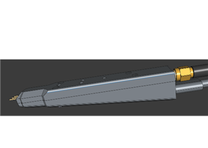
There is a 3D printable enclosure available.
All the files and details to build the probes can also be found on my Github project here:
https://github.com/paulvee/New-Differential-Probe-1-10-100MHz
Here is Bud's project with lots of details about the design:
https://hackaday.io/project/203296-a-slim-10x-100mhz-10mhz-1mhz-differential-probe/
Success and have fun!
Paul
A new 100MHz differential probe
Project images are for reference only. Actual production is based on the manufacturing files on the project page.
Please review the designer's notes (e.g., PCB thickness) and select the appropriate options.
PCBWay is not responsible
for issues caused by unsuitable parameter selections.
For more important ordering information, please refer to
Read More


Raspberry Pi 5 7 Inch Touch Screen IPS 1024x600 HD LCD HDMI-compatible Display for RPI 4B 3B+ OPI 5 AIDA64 PC Secondary Screen(Without Speaker)
BUY NOW

- Comments(1)
- Likes(4)
More by Paul Versteeg
-
 Diff Probe Power Supply (switching)
This is yet another power supply option for the differential probe.https://www.pcbway.com/project/sh...
Diff Probe Power Supply (switching)
This is yet another power supply option for the differential probe.https://www.pcbway.com/project/sh...
-
 Modifying a Hotplate to a Reflow Solder Station
This is a project to modify a UYUE 946C model hotplate and convert it to a reflow soldering station....
Modifying a Hotplate to a Reflow Solder Station
This is a project to modify a UYUE 946C model hotplate and convert it to a reflow soldering station....
-
 DIY PS503A front panel
This is the face plate for the DIY rebuild of the Tektronix PS503A dual tracking power supply.The in...
DIY PS503A front panel
This is the face plate for the DIY rebuild of the Tektronix PS503A dual tracking power supply.The in...
-
 DIY Rebuild of the Tektronix PS503A
DIY-PS503A-Power-SupplyDIY standalone version of the Tektronix PS503A dual tracking power supplyLab ...
DIY Rebuild of the Tektronix PS503A
DIY-PS503A-Power-SupplyDIY standalone version of the Tektronix PS503A dual tracking power supplyLab ...
-
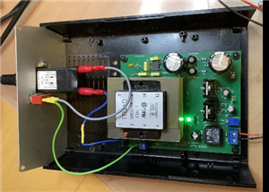 Dedicated Power Supply for the DIY rebuild of the Tektronix SG505 sine wave generator
This is a project to build a low noise, dedicated power supply for the very low distortion Tektronix...
Dedicated Power Supply for the DIY rebuild of the Tektronix SG505 sine wave generator
This is a project to build a low noise, dedicated power supply for the very low distortion Tektronix...
-
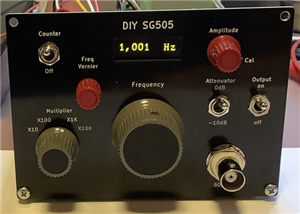 DIY Rebuild of the Tektronix SG505 high precision, low distortion sine wave generator
This is a DIY project to rebuild the Tektronix SG505 high precision very low distortion sine wave ge...
DIY Rebuild of the Tektronix SG505 high precision, low distortion sine wave generator
This is a DIY project to rebuild the Tektronix SG505 high precision very low distortion sine wave ge...
-
 Diff Probe Power Supply (Discrete)
This is a companion Daughter Board power supply for the new 10MHz and 1MHz differential probes liste...
Diff Probe Power Supply (Discrete)
This is a companion Daughter Board power supply for the new 10MHz and 1MHz differential probes liste...
-
 Diff Probe Power Supply (VREG-SOIC-8)
This is a daughter board for the new 100MHz differential probe listed in the Shared Projects.It supp...
Diff Probe Power Supply (VREG-SOIC-8)
This is a daughter board for the new 100MHz differential probe listed in the Shared Projects.It supp...
-
 A new 100MHz differential probe
This is a DIY 100MHz version of a new differential probe that was mostly designed by my friend Bud B...
A new 100MHz differential probe
This is a DIY 100MHz version of a new differential probe that was mostly designed by my friend Bud B...
-
 LORA-based Mailbox alarm
This information can be used to build a LORA-based mailbox receiver and a sender, using the same PCB...
LORA-based Mailbox alarm
This information can be used to build a LORA-based mailbox receiver and a sender, using the same PCB...
-
 SPI bus isolator
I needed a galvanically separated SPI interface between an ESP32 and an OLED display board.The volta...
SPI bus isolator
I needed a galvanically separated SPI interface between an ESP32 and an OLED display board.The volta...
-
 DiY Dynamic DC Load - Back Plate (3 of 3)
This is the Back Plate/Back Panel for a DIY Dynamic Load instrument
DiY Dynamic DC Load - Back Plate (3 of 3)
This is the Back Plate/Back Panel for a DIY Dynamic Load instrument
-
 DIY Dynamic DC Load - Face Plate (2 of 3)
This is the Face Plate/Front Panel for a DIY DC Dynamic Load instrument
DIY Dynamic DC Load - Face Plate (2 of 3)
This is the Face Plate/Front Panel for a DIY DC Dynamic Load instrument
-
 DIY Dynamic DC Load (1 of 3)
This is a DIY Dynamic Load instrument that can do many things professional instruments can do too.It...
DIY Dynamic DC Load (1 of 3)
This is a DIY Dynamic Load instrument that can do many things professional instruments can do too.It...
-
 10MHz OCXO frequency reference 2 of 2
This is the front panel PCB used for the 10MHz frequency reference.More details can be found on my B...
10MHz OCXO frequency reference 2 of 2
This is the front panel PCB used for the 10MHz frequency reference.More details can be found on my B...
-
 10MHz OCXO frequency reference 1 of 2
This is part of a 10MHz frequency reference that is based on an OCXO.The project is described in det...
10MHz OCXO frequency reference 1 of 2
This is part of a 10MHz frequency reference that is based on an OCXO.The project is described in det...
-
 10MHz GPSDO V4.1 (4 of 4)
This is the front panel for a high precision GPSDO ( GPS (GNSS) Disciplined Oscillator) with an outp...
10MHz GPSDO V4.1 (4 of 4)
This is the front panel for a high precision GPSDO ( GPS (GNSS) Disciplined Oscillator) with an outp...
-
 10MHz GPSDO V4.1 (3 of 4)
This is the front panel for a high precision GPSDO ( GPS (GNSS) Disciplined Oscillator) with an outp...
10MHz GPSDO V4.1 (3 of 4)
This is the front panel for a high precision GPSDO ( GPS (GNSS) Disciplined Oscillator) with an outp...
-
Programmable Mist Maker - XIAO / QT PY Extension
1061 2 1 -
RadioHAT - Raspberry Pi radio development platform
861 0 2 -
-
-
-
-
ARPS-2 – Arduino-Compatible Robot Project Shield for Arduino UNO
3322 0 6 -
A Compact Charging Breakout Board For Waveshare ESP32-C3
3930 3 8 -
AI-driven LoRa & LLM-enabled Kiosk & Food Delivery System
4316 2 2


