PCB Prototype the Easy Way

Full feature custom PCB prototype service.

Help Center
Sending a message
9:00 - 23:00, Mon.- Sun. (GMT+8)
Service hotlines
+86 571 8531 7532

9:00 - 18:00, Mon.- Fri. (GMT+8)

9:00 - 12:00, Sat. (GMT+8)

(Except Chinese public holidays)

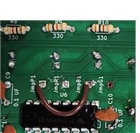
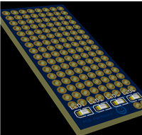
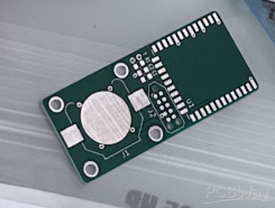
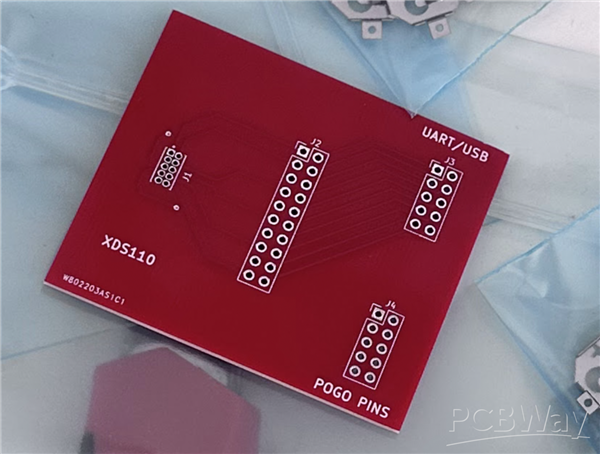
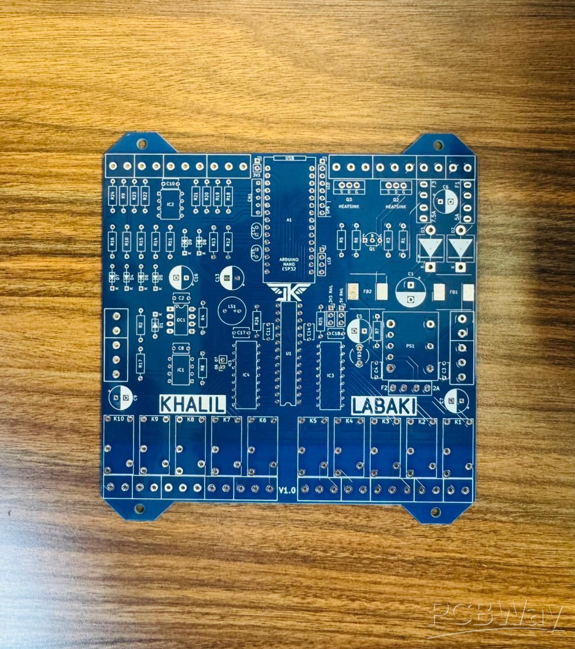
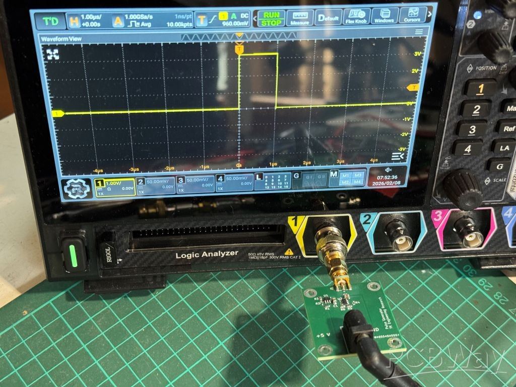
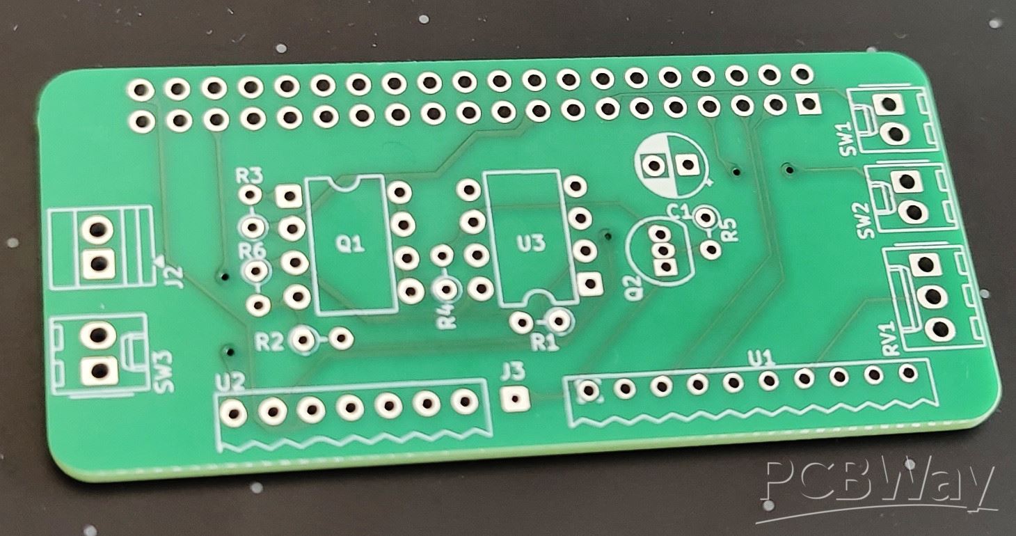
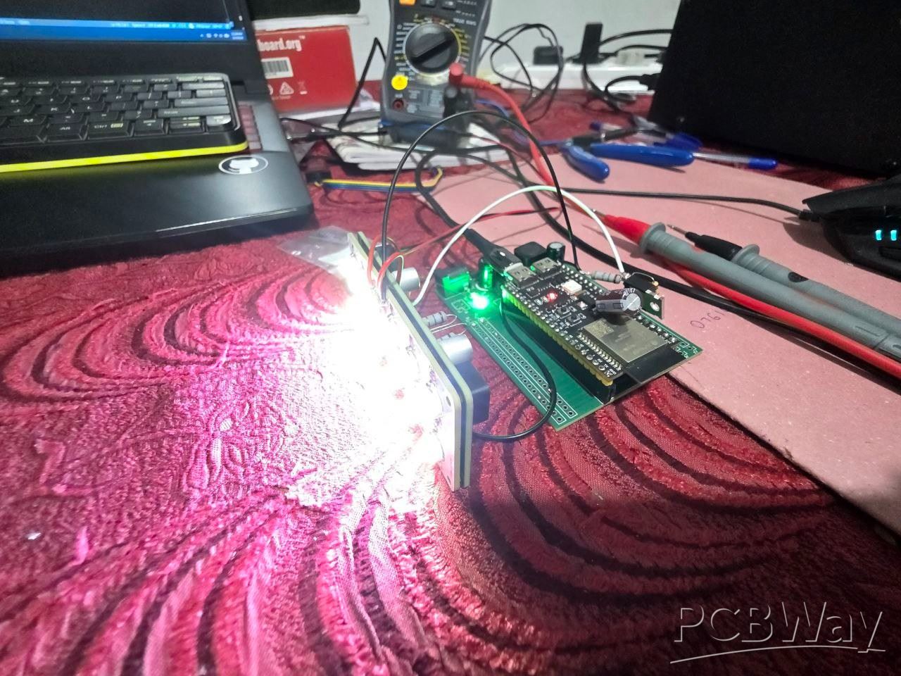
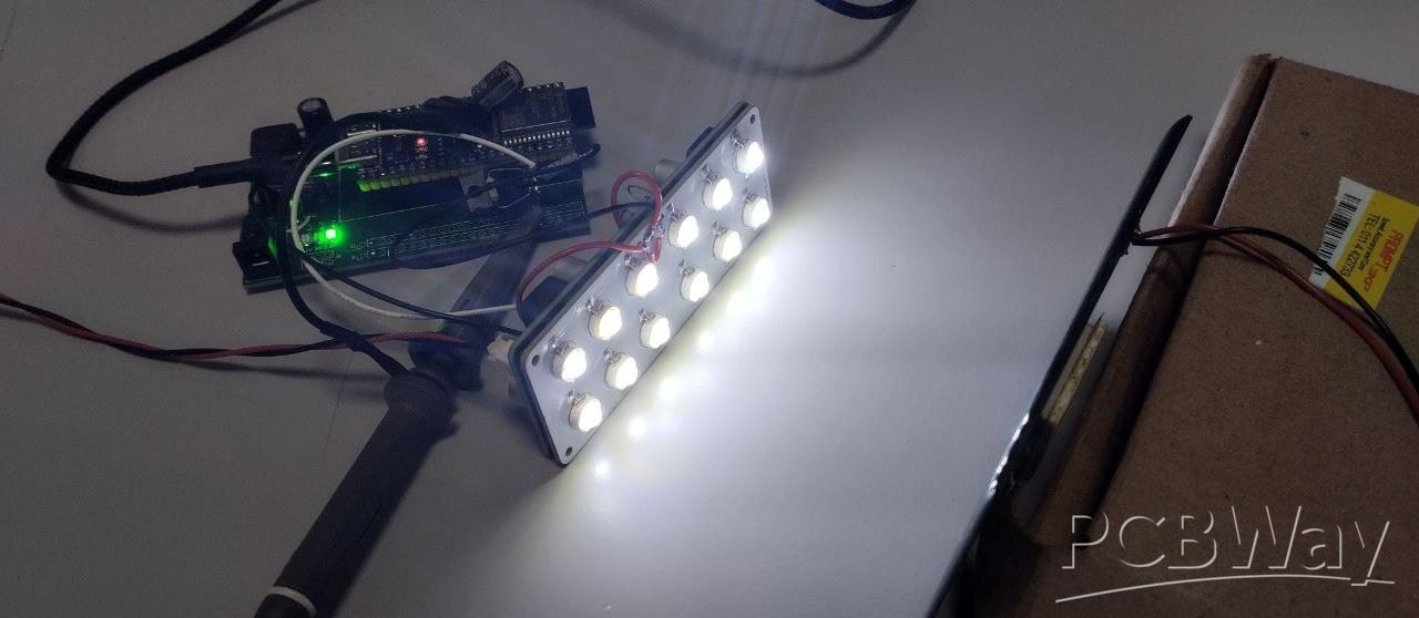
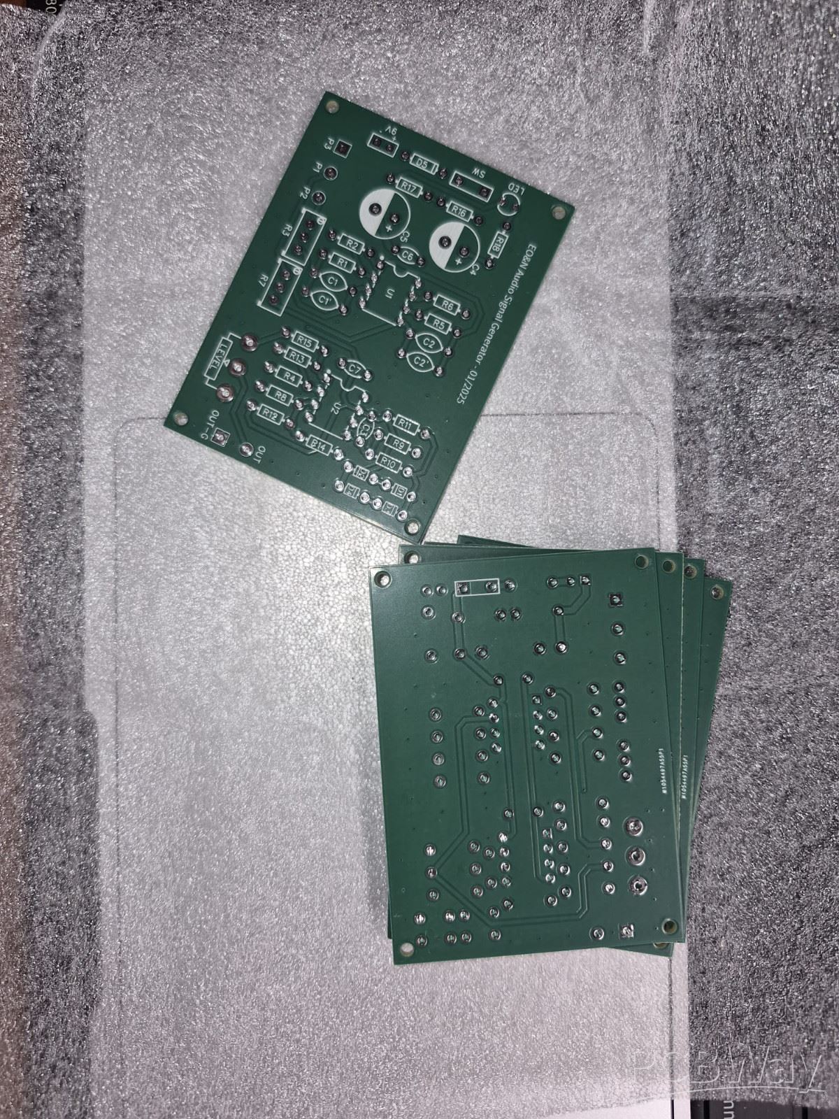
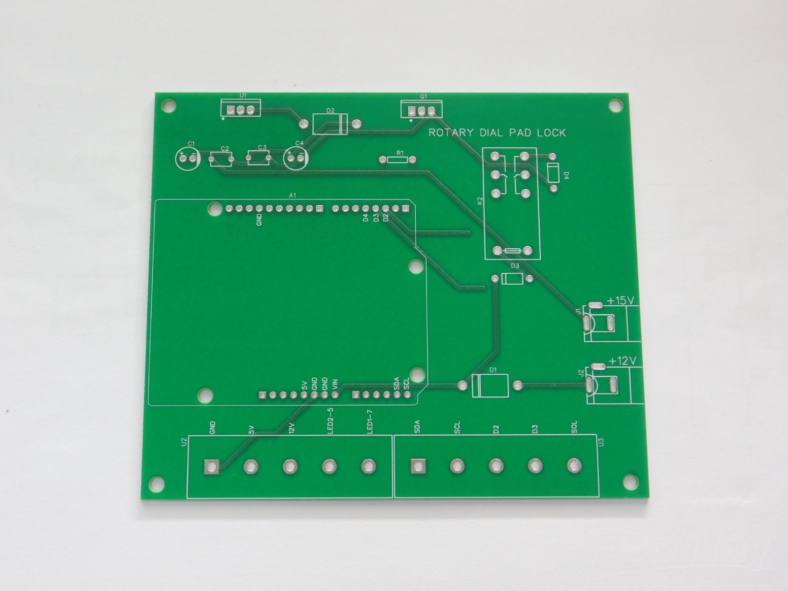
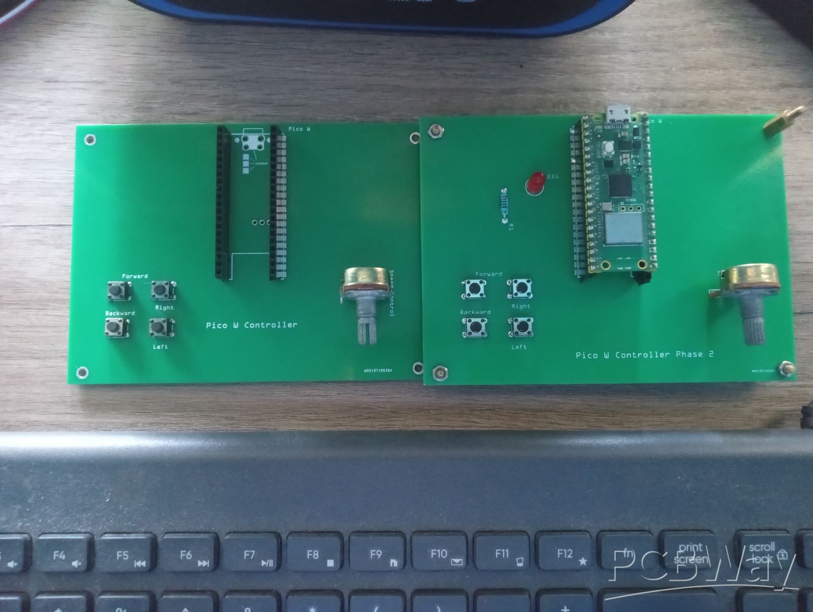
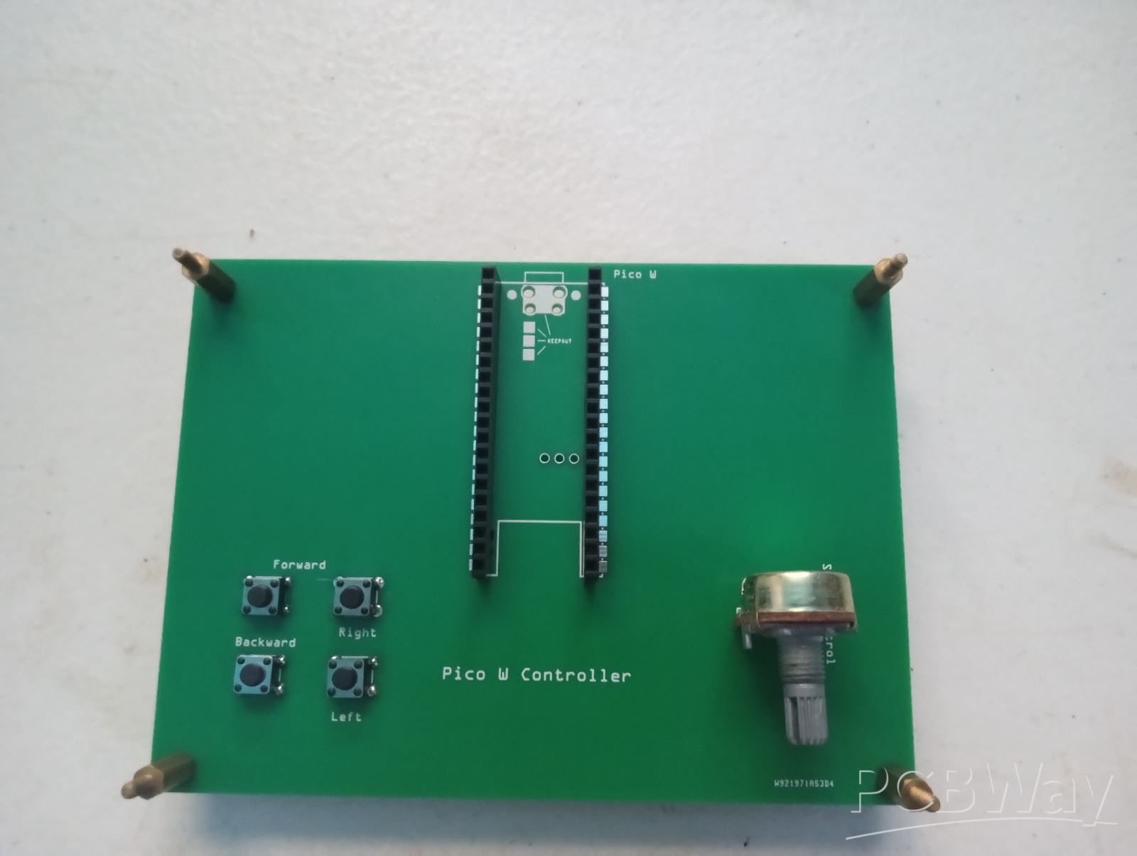
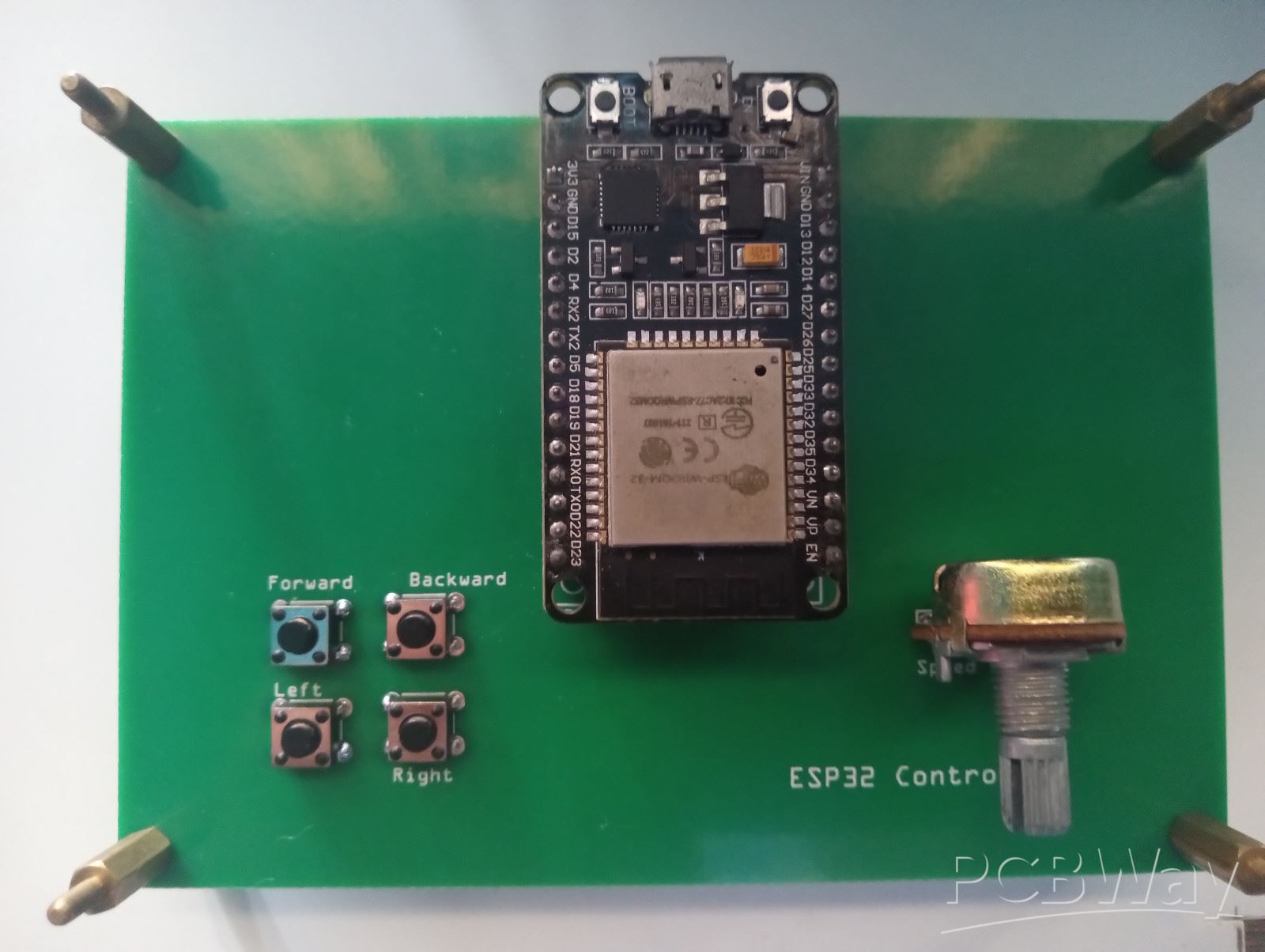
Example printed circuit boards manufactured by us.

We have the PCB manufacturing capabilities to build simple to complex bare boards.
Please review the example printed circuits below and let us know if you have any
questions or would like a formal quote.

Focus on high-end PCB design, R&D, production, sales, provide customers with high-level, high-speed, high-frequency, high-end,
high-density, high-difficulty HDI PCB design and other types of PCB proofing, customization, board manufacturing and bulk online
order purchase service. The products have covered high-end HDI buried blind hole PCB, 5G communication PCB board, high frequency
and high speed PCB, optical module PCB, semiconductor test, aerospace PCB circuit board and many other fields.

原图
Mouse over to zoom in

PCB Design and Layout

Problem case
Analysis
Improvement
Quote Now
Product Details
1. The dimensions do not match the drawings.

Analysis: The designer has indicated that the finished product size is 264*127mm in the PDF file. The usual practice of the manufacturer is to follow the center line of the frame in the illuminating file provided by the designer. In the actual board, the center line of the design is 264.62*. 127.66mm, the border line width is 0.64mm. According to this design, the original intention is to take the inner edge of the border line as the shape. This creates a different way of understanding between design and production.

Improvement: The dimensions of each document must be consistent. By default, the center distance of the border line is the outer dimension.

2. Imposition method description blur

Analysis: V-CUT is not indicated in the provided panel file and may be directly connected by the bridge when the manufacturer processes it.

Improvement: Mark "V-CUT" in the position where V cutting is required. Current panel methods includes V-CUT, bridge, bridge + stamp hole, V-CUT + bridge + stamp hole.

3. The shape is complex and cannot be determined.

Analysis: The outline frame provided by the designer seems to be closed, according to the usual practice, the small board is milled off. After the experienced technicians communicate with the designer, it is determined that the small board can only be milled on three sides, and the other side remains for V-CUT, it is intended to maintain the balance of the board.

Improvement: If the designer does not explicitly indicate that the small board is to be milled, the outline drawing needs to be displayed in dotted lines to determine the shape.

4. The mechanical layer or the non-circuit layer has a circle, there is no relevant explanation whether it is to be drilled here, and which hole is drilled.

Analysis: The designer draws some circles and lines in the outline file, and there are drill holes in the drilling file. The original intention is to mill the grooves surrounded by the lines for easy installation (There are circles in the outline file, meanwhile there are holes in the drilling file, which are ignored during the production).

Improvement: When there are slots in the shape design and there are holes in the drilling file, you need to indicate whether you need to mill.

5. There are flower pads across the isolation strip.

Analysis: The hole straddles the isolation strip, causing both the inner and outer parts to conduct;

Improvement: If the two parts are the same network, the drill can be spanned on the barrier, otherwise this should be avoided.

6. The isolation zone has a narrow area where the flower pad is blocked.

Analysis: the flower pad is blocked in a narrow area of the isolation band.

Improvement: For the designer, the logical network is normal, but the actual fabricated board network may be disconnected in physical network.

7. Conductor copper is unevenly distributed.

Analysis: The copper distribution of the conductor is uneven, the large-area grounding is concentrated at one end of the board, and the fine isolated circuit is at the other end, resulting in uneven plating distribution, sometimes causing the plating layer to burn, the plating of the via hole is rough or the board is excessively warped.

Improvement: Place an isolated plated/baffle block(disc/square/grid) in the blank area of the substrate. And close to isolated lines or holes for even distribution.

Related Products View more >>
  • FPC/R-FPC

    Flexible Part Circuit Design Requirements

Contact Us!

Our customer service
ready for your PCB

+86-571-85317532

quotesI am impressed with the quality of the boards, the delivery time and responce to all my questions. Best price excellent service and speedy delivery. When I need another board I will certainly use this supplier. "

-Bill Robinson Company

quotesспасибо за платы! платы очень хорошего качества. надежный продавец. оперативно отвечал на вопросы. заказ выполнили и отправили очень быстро.Заказываю платы не в первый раз - как всегда только лучшие впечатления. 5+++. 4 числа отправил файлы 26-го забрал на почте в Москве."

-FVL. SKU Company