


arduino mega password security system shield
this is a sheild for an arduino mega. this security system can be accesed using RFID and IR and a keypad for the password.
copy the code and get ur IR and RFID UID numbers using the dumpinfo code and then put it in the relevent place don't worry i have putt XX XX XX XX for that type the RFID code and just erasethe other numbers for the ir UID number
u will need: 16x2 LCD DISPLAY, 3X4 MATRIX KEYPAD,ARDUINO MEGA WITH THIS SHEILD,MALE PIN HEADERS,A LOT OF LEAD, MFRC522 RFID READER WITH CARDS OR MABYE TAGS, A 10K POTENTIOMETER.
copy this code and paste it in the arduino software
/*

 * THIS IS A MULTIPURPOSE PASSWORD SECURITY SYSTEM USING RFID AND A KEYPAD AND A REMOTE.
 *
 * IF U WANT TO TYPE PASSWORD, THEN WAIT TILL IT ASKES TO "SCAN CARD OR TYPE" AND TYPE THE NUMBER
 * IF U WANT TO USE THE CARD THE CARD HAS TO BE REGISTERED FIRST.ALL U HAVE TO DO IS PRESS AND HOLD THE RED BUTTON AND SCAN THE CARD.
 * OR ELSE U CAN JUST USE THE ARDUINO REMOTE ( 1,2,3 ARE TO SWITCH LIGHT_1,LIGHT_2 AND FAN RESPECTIVELY) (PLUS AND MINUS AND PREV AND NEXT ARE USED TO CLOSE THE SERVO MOTOR) (AND CH AND 0 ARE TO SWITCH ALL THE SYSTEMS AND SWITCH OFF ALL THE SYSTEMS OFF REESPECTIVELY)
 *
 *
 * KEYPAD CONNECTIONS (D1,D2,D3,D4,D5,D6,D7)
 * IR RECEIVER PIN 10
 * SERVO SIGNAL 8
 * MFRC522 RST PIN 9
 * LCD PINS (A1,A2,A3,A4,A5)
 * GREEN LED 15
 * RED LED 14
 * SWITCH 16
 * POTENTIOMETER WIPER PIN (VO)OF LCD

GND PINS = SERVO(BROWN WIRE)
           LCD(VSS,RW,K,)
           MFRC522 GND PIN
           SWITCH GND PIN
           IR RECIVER GND PIN
           POTENTIOMETER GND

+5v PINS = LCD (VDD,A)
           SERVO (RED WIRE)
           SWITCH +5V PIN
           IR RECIVER VCC PIN

3.3V PINS  =  MFRC522 VCC PIN ONLY


 * Typical pin layout used:
 * -----------------------------------------------------------------------------------------
 *             MFRC522      Arduino       Arduino   Arduino    Arduino          Arduino
 *             Reader/PCD   Uno/101       Mega      Nano v3    Leonardo/Micro   Pro Micro
 * Signal      Pin          Pin           Pin       Pin        Pin              Pin
 * -----------------------------------------------------------------------------------------
 * RST/Reset   RST          9             5         D9         RESET/ICSP-5     RST
 * SPI SS      SDA(SS)      10            53        D10        10               10
 * SPI MOSI    MOSI         11 / ICSP-4   51        D11        ICSP-4           16
 * SPI MISO    MISO         12 / ICSP-1   50        D12        ICSP-1           14
 * SPI SCK     SCK          13 / ICSP-3   52        D13        ICSP-3           15
 --------------------------------------------------------------------------------------------
*/

#include <IRremote.h>
#include <Servo.h>
#include <deprecated.h>
#include <MFRC522.h>
#include <MFRC522Extended.h>
#include <require_cpp11.h>
#include <SPI.h>
#include <MFRC522.h>
#include <LiquidCrystal.h>
#include <Keypad.h>


#define SS_PIN 53
#define RST_PIN 9

#define BUTTON_PREV 0xFF22DD
#define BUTTON_next 0xFF02FD
#define BUTTON_PLUS 0xFFA857  // type the ir numbers here
#define BUTTON_MINUS 0xFFE01F  // example :  0x XX_XX_XX

#define redLED 14 //define the LED pins
#define greenLED 15

#define LIGHT_1  22
#define LIGHT_2 24
#define FAN 26

#define SD_ChipSelectPin 17

char* password ="32369"; //create a password
int pozisyon = 0; //keypad position
int RFIDState= 0;
int SENSORState=0;
int RECV_PIN = 10;

const byte rows = 4; //number of the keypad's rows and columns
const byte cols =3;
const int RFID = 16;
const int SENSOR = 17;

char keyMap [rows] [cols] = { //define the cymbols on the buttons of the keypad

  {'1', '2', '3', },
  {'4', '5', '6', },
  {'7', '8', '9',},
  {'*', '0', '#',}
};

byte rowPins [rows] = {1, 2, 3, 4}; //pins of the keypad
byte colPins [cols] = {5, 6, 7, };
bool door = true;

Servo myservo;
IRrecv irrecv(RECV_PIN);
decode_results results;
MFRC522 mfrc522(SS_PIN, RST_PIN);
Keypad myKeypad = Keypad( makeKeymap(keyMap), rowPins, colPins, rows, cols);
LiquidCrystal lcd (A0, A1, A2, A3, A4, A5); // pins of the LCD. (RS, E, D4, D5, D6, D7)


void setup()
{
  pinMode(23,OUTPUT);
  pinMode(SENSOR,INPUT);
  pinMode(RFID,INPUT);
  irrecv.enableIRIn();
  SPI.begin();
  mfrc522.PCD_Init();
  myservo.attach(8);
  myservo. write(180);
  lcd.begin(16, 2);
  pinMode(redLED, OUTPUT);
  pinMode(greenLED, OUTPUT);
  digitalWrite (FAN,OUTPUT);
  digitalWrite(LIGHT_1,OUTPUT);
  digitalWrite(LIGHT_2,OUTPUT);
  digitalWrite (22,LOW);
  digitalWrite(24,LOW);
  digitalWrite(26,HIGH);
  digitalWrite(23,LOW);
  setLocked (true);
  lcd.setCursor(0, 0);
  lcd.print("    WELCOME!");
  delay(2000);
  lcd.clear();
  lcd.setCursor(0, 0);
  lcd.print("PRESS SWITCH AND ");
  lcd.setCursor(0,1);
  lcd.print("HOLD TO SCAN TAG");
  delay(4000);

}

void loop() {


{
  lcd.clear();
  RFIDState = digitalRead(RFID);

 if (RFIDState == LOW) {

  char whichKey = myKeypad.getKey();

  lcd.setCursor(0, 0);
  lcd.print("TYPE PASSWORD OR");
  lcd.setCursor(0,1);
  lcd.print("   SCAN CARD");

if (irrecv.decode(&results))
  {

if (results.value == BUTTON_PLUS)
    {
      lcd.clear();
      lcd.setCursor(0,0);
      lcd.print("   DOOR OPEN!");
      myservo.write(0);
      delay(3000);
      myservo.write(180);
       lcd.clear();
      lcd.print("  DOOR CLOSED!");
      delay(1000);
    }

if (results.value == BUTTON_MINUS)
    {
      lcd.clear();
      lcd.setCursor(0,0);
      lcd.print("   DOOR CLOSED!");
      myservo.write(180);
      delay(2000);
    }

if (results.value == BUTTON_next)
    {
 lcd.clear();
      lcd.setCursor(0,0);
      lcd.print("   DOOR CLOSED!");
      myservo.write(180);
      delay(2000);
    }


if (results.value == BUTTON_PREV)

    {
 lcd.clear();
      lcd.setCursor(0,0);
      lcd.print("   DOOR OPEN!");
      myservo.write(0);
      delay(3000);
      myservo.write(180);
       lcd.clear();
      lcd.print("  DOOR CLOSED!");
      delay(1000);
    }


    irrecv.resume();
}

else
  {

   if(whichKey == password [pozisyon]){

    pozisyon ++;
  }
  if(pozisyon == 5){
    setLocked (false);
   {
    DOOR_OPEN();

   }
  }
  delay(100);
  }
 }
}
  if (RFIDState == HIGH)
 {
  lcd.clear();
  lcd.setCursor(0, 0);
  lcd.print("Put your card to");
  lcd.setCursor(0, 1);
  lcd.print("the reader......");
  delay(300);

  // Look for new cards
  if ( ! mfrc522.PICC_IsNewCardPresent())
  {
    return;

  }
  // Select one of the cards
  if ( ! mfrc522.PICC_ReadCardSerial())
  {
    return;
  }

  //Show UID on serial monitor
  Serial.print("UID tag :");
  String content= "";
  byte letter;
  for (byte i = 0; i < mfrc522.uid.size; i++)
  {
     Serial.print(mfrc522.uid.uidByte[i] < 0x10 ? " 0" : " ");
     Serial.print(mfrc522.uid.uidByte[i], HEX);
     content.concat(String(mfrc522.uid.uidByte[i] < 0x10 ? " 0" : " "));
     content.concat(String(mfrc522.uid.uidByte[i], HEX));
  }
  Serial.println();
  Serial.print("Message : ");
  content.toUpperCase();

  if (content.substring(1) == "XX XX XX XX"|| content.substring(1) == "XX XX XX XX"||content.substring(1) == "XX XX XX XX"||content.substring(1) == "XX XX XX XX"||content.substring(1) == "XX XX XX XX")
  {
   DOOR_OPEN();

  }
else   {
    lcd.clear();
    lcd.setCursor(0, 0);
    lcd.print("Access denied");
    Serial.println(" Access denied");
    delay(1500);
   }
 }
 delay(1);
}

void setLocked(int locked){
  if(locked){
    digitalWrite(redLED, HIGH);
    digitalWrite(greenLED, LOW);
    }
    else{
    digitalWrite(redLED, LOW);
    digitalWrite(greenLED, HIGH);
    }
  }

  void DOOR_OPEN()
  {

    digitalWrite(redLED, LOW);
    digitalWrite(greenLED, HIGH);
    myservo.write(0);
    lcd.clear();
    lcd.setCursor(0, 0);
    lcd.print(" ACCESS GRANTED!");
    delay(1000);
    lcd.clear();
    lcd.print("      HELLO   ");
    lcd.setCursor(0, 1);
    lcd.print("UR DOOR IS OPEN!");
    delay(3000);
    lcd.clear();
    lcd.print("door is closing in");
    lcd.setCursor(0,1);
    lcd.print("       05");
    delay(1000);
    lcd.clear();
    lcd.print("door is closing in");
    lcd.setCursor(0,1);
    lcd.print("       04");
    delay(1000);
    lcd.clear();
    lcd.print("door is closing in");
    lcd.setCursor(0,1);
    lcd.print("       03");
    delay(1000);
    lcd.clear();
    lcd.print("door is closing in");
    lcd.setCursor(0,1);
    lcd.print("       02");
    delay(1000);
    lcd.clear();
    lcd.print("door is closing in");
    lcd.setCursor(0,1);
    lcd.print("       01");
    delay(1000);
    lcd.clear();

    myservo.write(180);
    lcd.clear();
    lcd.print("DOOR IS CLOSED!!!!");
    delay(2000);
    lcd.clear();
   loop();
}arduino mega password security system shield
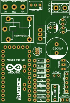
Project images are for reference only. Actual production is based on the manufacturing files on the project page.
Please review the designer's notes (e.g., PCB thickness) and select the appropriate options.
PCBWay is not responsible
for issues caused by unsuitable parameter selections.
For more important ordering information, please refer to
Read More


Raspberry Pi 5 7 Inch Touch Screen IPS 1024x600 HD LCD HDMI-compatible Display for RPI 4B 3B+ OPI 5 AIDA64 PC Secondary Screen(Without Speaker)
BUY NOW

- Comments(1)
- Likes(3)
- 2 USER VOTES
- YOUR VOTE 0.00 0.00
-
10design
-
10usability
-
10creativity
-
10content

-
10design
-
10usability
-
10creativity
-
10content
More by umar_khalid
-
 DIY ARDUINO UNO BOARD
this is a regular arduino board which all u need to do is solder the components and use a (FT232RL) ...
DIY ARDUINO UNO BOARD
this is a regular arduino board which all u need to do is solder the components and use a (FT232RL) ...
-
 ARDUINO IR CONTROLLED RELAY (AC/DC)
This circuit needs maximum 5v - 7v if powered directly through DC power supply only. If ur supplyi...
ARDUINO IR CONTROLLED RELAY (AC/DC)
This circuit needs maximum 5v - 7v if powered directly through DC power supply only. If ur supplyi...
-
 LIGHT AND MOTION SENSITIVE LAMP CIRCUIT
This is a circuit which activates a RELAY when the envoiroment is dark and when there is a movement ...
LIGHT AND MOTION SENSITIVE LAMP CIRCUIT
This is a circuit which activates a RELAY when the envoiroment is dark and when there is a movement ...
-
 DIY ARDUINO PRO MINI 2.0 (upgraded version)
This is a DIY arduino PRO mini which is like a regular arduino pro minni but it has less components ...
DIY ARDUINO PRO MINI 2.0 (upgraded version)
This is a DIY arduino PRO mini which is like a regular arduino pro minni but it has less components ...
-
 DIY SMD ARDUINO UNO
This is a regular arduino board which contains extra features such as an extra VCC/GND rail and it u...
DIY SMD ARDUINO UNO
This is a regular arduino board which contains extra features such as an extra VCC/GND rail and it u...
-
 DIY SMD ARDUINO UNO R3
This is a regular arduino board which contains extra features such as an extra VCC/GND rail and it u...
DIY SMD ARDUINO UNO R3
This is a regular arduino board which contains extra features such as an extra VCC/GND rail and it u...
-
 LDR CONTROLLED RELAY MODULE SMD
This is a simple LDR dark sensor project which is designed to turn ON a relay (when there is light) ...
LDR CONTROLLED RELAY MODULE SMD
This is a simple LDR dark sensor project which is designed to turn ON a relay (when there is light) ...
-
 DIY ARDUINO UNO SHEILD SMD
This is a simple arduino sheild that can run on it's own as an arduino uno once it's powered...
DIY ARDUINO UNO SHEILD SMD
This is a simple arduino sheild that can run on it's own as an arduino uno once it's powered...
-
 DIY arduino UNO sheild
This is a simple arduino sheild that can run on it's own as an arduino uno once it's powered...
DIY arduino UNO sheild
This is a simple arduino sheild that can run on it's own as an arduino uno once it's powered...
-
 DIY 4017 CLAP SWITCH CIRCUIT.
THIS IS A SIMPLE CLAP SWITCH CCIRCUIT THAT USES A 4017ic DECODER. WHEN U CLAP ONCE, IT TURNS THE R...
DIY 4017 CLAP SWITCH CIRCUIT.
THIS IS A SIMPLE CLAP SWITCH CCIRCUIT THAT USES A 4017ic DECODER. WHEN U CLAP ONCE, IT TURNS THE R...
-
 DIY DIGITAL CLOCK
THIS IS A SIMPLE DIGITAL CLOCK THAT WORKS WITH A 9V BATTERY AND CAN BE SET JUST THREE BUTTONS.IF U L...
DIY DIGITAL CLOCK
THIS IS A SIMPLE DIGITAL CLOCK THAT WORKS WITH A 9V BATTERY AND CAN BE SET JUST THREE BUTTONS.IF U L...
-
 DIY ARDUINO UNO R3 SMD
THIS WORKS AS A REGULAR ARDUINO UNO WITH AN SMD ATMEGA 328P.U JUST NEED TO SOLDER THE COMPONENTS AND...
DIY ARDUINO UNO R3 SMD
THIS WORKS AS A REGULAR ARDUINO UNO WITH AN SMD ATMEGA 328P.U JUST NEED TO SOLDER THE COMPONENTS AND...
-
 arduino mega password security system shield
this is a sheild for an arduino mega. this security system can be accesed using RFID and IR and a ke...
arduino mega password security system shield
this is a sheild for an arduino mega. this security system can be accesed using RFID and IR and a ke...
-
 LED CHASER
this is a simple circuit using an ic 4017 and an ic 555 timer . u can adjust the frequency using the...
LED CHASER
this is a simple circuit using an ic 4017 and an ic 555 timer . u can adjust the frequency using the...
-
 LED CHASER
this is a simple circuit using an ic 4017 and an ic 555 timer . u can adjust the frequency using the...
LED CHASER
this is a simple circuit using an ic 4017 and an ic 555 timer . u can adjust the frequency using the...
-
 DIY arduino uno r3
DIY arduino uno circuit.its used just like a regular arduino uno all u gotta do is get the component...
DIY arduino uno r3
DIY arduino uno circuit.its used just like a regular arduino uno all u gotta do is get the component...
-
 ARDUINO UNO R3
AN ARDUINO UNO R3 DIY PROJECTU WILL NEED: ATmega 328P, 22PF ceramic capacitors(3), a few female pin ...
ARDUINO UNO R3
AN ARDUINO UNO R3 DIY PROJECTU WILL NEED: ATmega 328P, 22PF ceramic capacitors(3), a few female pin ...
-
 2 WAY INTERCOM CIRCUIT_20181119155207
THIS IS A 2 WAY INTERCOM CIRCUIT, IT WORKS LIKE A WALKIE TALKIE BUTWITH WIRES
2 WAY INTERCOM CIRCUIT_20181119155207
THIS IS A 2 WAY INTERCOM CIRCUIT, IT WORKS LIKE A WALKIE TALKIE BUTWITH WIRES
-
Programmable Mist Maker - XIAO / QT PY Extension
1061 2 1 -
RadioHAT - Raspberry Pi radio development platform
860 0 2 -
-
-
-
-
ARPS-2 – Arduino-Compatible Robot Project Shield for Arduino UNO
3322 0 6 -
A Compact Charging Breakout Board For Waveshare ESP32-C3
3929 3 8 -
AI-driven LoRa & LLM-enabled Kiosk & Food Delivery System
4315 2 2


