


|
KiCADKicad
|
Stepper Motor Driver
Like any motor, stepper motors consist of a stator and a rotor, but without brushes. Unlike conventional brushless DC motors, the variable electromagnetic field that controls movement is formed not by the switching of the coils by the brushes on the rotor, but by the way the pulses are applied to the stator coils. The stepper motor rotor can be with permanent magnet, a variable reluctant or a mixture of the two. By controlling the field between the stator and the rotor, a very precise one-way movement can be obtained. Therefore, stepper motors are supplied with rectangular voltage pulses of appreciable current. They are stepper motors whose pitch is 0.9 °; 1.8 °; 3.6 °, etc. Compared to the 360 ??° of a circle, a step of 0.9 ° involves, at a complete rotation, the execution of 400 individual steps, controlled by the control logic of the pulses applied on the four coils. , especially by thermal effect, which in a stepper motor, are important, the following observations are made; at low travel speeds (low frequency control) the stepper develops a very high torque at its shaft. If they are supplied with low voltage fixed (stabilized) voltage sources, no special problems occur; however, if the control frequency increases (travel speed increases) the torque decreases even more due to the high impedances of the coils, an effect manifested at high frequencies. Three power supply modes are possible, - powering the coils from a "chopper" (switching source), with very high voltage, so that at high speeds the filling factor increases in the source control, - power supply from the voltage source of high value in series with a ballast resistor - the resistor limits the current through the stator: - supply from a constant current source that will keep the current through the coils (the same, regardless of speed) if the speed increases and increases the voltage accordingly. There are disadvantages what regarding the first two methods (the realization of a switching source for inductive loads must be well tolerated, and a power series resistor denotes high power consumption and heat dissipation.) The use of a current source (at high control frequencies) is the most indicated. , it keeps the current constant through the coils (so constant torque), the voltage can take any values ??depending on the torque required by the motor. electrical call, there is an oscillator made NAND gate U1B, the frequency being controlled from R1. With the help of this oscillator the annual control of the stepper movement or the driver test is allowed (via the OSC pin). For this operation the OSC pin (from J1) is connected to STP, and DIR to GND. To reverse the direction of rotation, DIR is connected to + 5V. IRFZ44 transistors can switch without radiator load currents up to 5... 6A. The supply of logic circuits is done with + 5V from L7805. The minimum supply voltage of the assembly is 8V, and the maximum (imposed by LM7805) is 35V. The maximum supply voltage of 35V is applied to connector J2 (in the middle of the block connector bar). Connect the wires of the stepper to each 3-pin connector at both ends of the PCB. The V + signal is common. The other signals corresponding to the coils are M1A and M2A, respectively M1B and M2B.

Stepper Motor Driver
Project images are for reference only. Actual production is based on the manufacturing files on the project page.
Please review the designer's notes (e.g., PCB thickness) and select the appropriate options.
PCBWay is not responsible
for issues caused by unsuitable parameter selections.
For more important ordering information, please refer to
Read More


Raspberry Pi 5 7 Inch Touch Screen IPS 1024x600 HD LCD HDMI-compatible Display for RPI 4B 3B+ OPI 5 AIDA64 PC Secondary Screen(Without Speaker)
BUY NOW


- Comments(2)
- Likes(0)
 More by cris 🙂
-
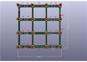
 Dynamic decoration with LEDs and more
Hello everyone!As you can see in the title, we have a circuit with LEDs, many LEDs, it's a 4x4 LEDs ...
Dynamic decoration with LEDs and more
Hello everyone!As you can see in the title, we have a circuit with LEDs, many LEDs, it's a 4x4 LEDs ...
-
 LEDs Stars
Hello everyone! I'm signing up for this competition with a small project designed to attract your a...
LEDs Stars
Hello everyone! I'm signing up for this competition with a small project designed to attract your a...
-
 Audio amplifier with LM386 (and BASS boost)
Hello everyone!Circuit descriptionThe LM386 is quite a ve...
Audio amplifier with LM386 (and BASS boost)
Audio amplifier with LM386 (and BASS boost)Hello everyone!Circuit descriptionThe LM386 is quite a ve...
-
 Audio amplifier 25W TDA2030
A fairly well-known and interesting montagePresentationThe presented audi...
Audio amplifier 25W TDA2030
Audio amplifier 25W TDA2030A fairly well-known and interesting montagePresentationThe presented audi...
-
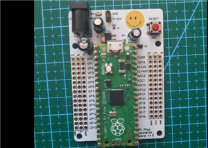 Raspberry Pi Pico Expansion Board
Hello everyone!UPDATE!!!I made some changes, routing in particular, and freed up the board of a few ...
Raspberry Pi Pico Expansion Board
Hello everyone!UPDATE!!!I made some changes, routing in particular, and freed up the board of a few ...
-
 Adjustable voltage power supply
Among the most important electronic devices in the electronics laboratory is the voltage source. Thi...
Adjustable voltage power supply
Among the most important electronic devices in the electronics laboratory is the voltage source. Thi...
-
 Digital Clock with AT89C2051
Circuit OperationShort SW2 presses cycle through displaying the current time in HH:MM and MM:SS form...
Digital Clock with AT89C2051
Circuit OperationShort SW2 presses cycle through displaying the current time in HH:MM and MM:SS form...
-
 Switch based light sensor
Hi!The circuit shown can be used to turn on the light in the garden, or some light panels / advertis...
Switch based light sensor
Hi!The circuit shown can be used to turn on the light in the garden, or some light panels / advertis...
-
 LM3909 flashing indicator
I present to you a circuit which is a little outdated, but quite pleasant for some, I saw that this ...
LM3909 flashing indicator
I present to you a circuit which is a little outdated, but quite pleasant for some, I saw that this ...
-
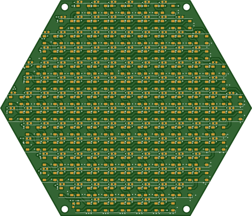 Hexagonal Panel with WS2812B LEDs
Hi makers!I created a hexagonal PCB with many WS2812B LEDs, 144 in total, for which I thought of pla...
Hexagonal Panel with WS2812B LEDs
Hi makers!I created a hexagonal PCB with many WS2812B LEDs, 144 in total, for which I thought of pla...
-
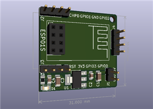 ESP01S Minimal Board
Hi makers!I created this small PCB for ESP01S because before I was using a DIY version and then I bo...
ESP01S Minimal Board
Hi makers!I created this small PCB for ESP01S because before I was using a DIY version and then I bo...
-
 4x4x4 cube with blue LEDs
Hi makers!I know that these days there are many variations of LEDs, for example SMDs are smaller and...
4x4x4 cube with blue LEDs
Hi makers!I know that these days there are many variations of LEDs, for example SMDs are smaller and...
-
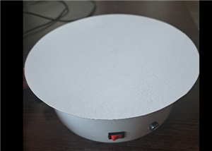 Low cost turntable 😁
Hi makers!I'm entering this competition with a small project that I've wanted to make for some time,...
Low cost turntable 😁
Hi makers!I'm entering this competition with a small project that I've wanted to make for some time,...
-
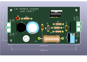 A DIY charger for 12V battery
Hello everyone!I present to you a project that really didn't reach its final state, until recently. ...
A DIY charger for 12V battery
Hello everyone!I present to you a project that really didn't reach its final state, until recently. ...
-
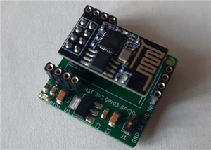 ESP01 board
Hello PCBWayers!You probably know that ESP01S/01 boards can be a little difficult to use in an easie...
ESP01 board
Hello PCBWayers!You probably know that ESP01S/01 boards can be a little difficult to use in an easie...
-
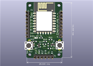 ESP12F Board
Hello makers!Some time ago I had a shopping coupon and I thought about making some simple PCBs with ...
ESP12F Board
Hello makers!Some time ago I had a shopping coupon and I thought about making some simple PCBs with ...
-
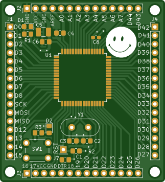
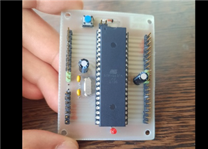 ATMega32 Board
Hi !I remembered this simple project I made for myself, you can use it with an ATMega32 or ATMega16 ...
ATMega32 Board
Hi !I remembered this simple project I made for myself, you can use it with an ATMega32 or ATMega16 ...
-
 AT90CAN128
Hello makers!Here is a guy who likes to build various, small, electronic circuits, and through this ...
AT90CAN128
Hello makers!Here is a guy who likes to build various, small, electronic circuits, and through this ...
-
Programmable Mist Maker - XIAO / QT PY Extension
1074 2 1 -
RadioHAT - Raspberry Pi radio development platform
891 0 2 -
-
-
-
-
ARPS-2 – Arduino-Compatible Robot Project Shield for Arduino UNO
3334 0 6 -
A Compact Charging Breakout Board For Waveshare ESP32-C3
3945 3 8 -
AI-driven LoRa & LLM-enabled Kiosk & Food Delivery System
4335 2 2


