|
|
ESP8266 |
x 1 | |
|
|
Buzzer |
x 1 | |
|
|
LED |
x 1 | |
|
|
Servo Motor (180) |
x 1 | |
|
|
Ultrasonic Sensor |
x 1 |

|
arduino IDEArduino
|
|

|
KiCADKicad
|
Radar System
# ESP8266 Radar System - Complete Documentation
---
## 1. Project Overview
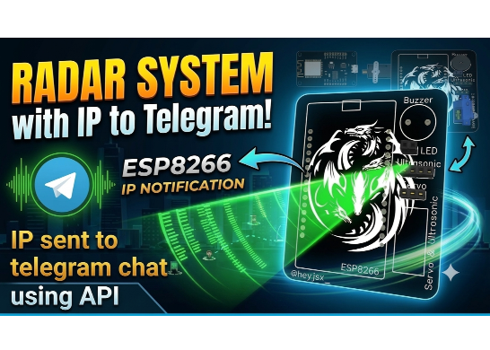
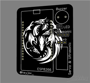
This is an ESP8266-based Radar System that uses an ultrasonic sensor (HC-SR04) to detect objects and display them on a real-time radar visualization. The system features a servo motor for 180-degree scanning, a web-based radar display, Telegram notifications, and local buzzer/LED alerts.
---
## 2. Features
Real-time radar display accessible via web browser with 180-degree scanning capability. Object detection from 2cm to 400cm with accuracy of plus or minus 0.3cm. Web interface updates at 25 frames per second. Buzzer and LED alerts activate when objects are detected within 20cm. Telegram bot sends IP address and system status on startup. Mobile-responsive web interface works on all devices. No AP mode fallback; requires WiFi connection to operate.
---
## 3. Hardware Connections
### Pin Connection Diagram
ESP8266 Pin → Component Connection
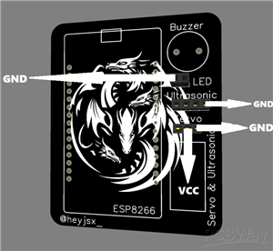
D5 → Ultrasonic Sensor TRIG Pin
D6 → Ultrasonic Sensor ECHO Pin
D4 → Servo Motor Signal Pin (Orange/Yellow wire)
D7 → Buzzer Positive Pin
D8 → LED Anode (Long leg) with 220Ω resistor in series
VIN (5V Output) → Servo Motor VCC (Red wire) and Ultrasonic Sensor VCC
GND (Ground) → All components GND pins
---
## 4. Software Requirements
### Required Libraries
UniversalTelegramBot by Brian Lough - Required for Telegram notifications. Install through Arduino Library Manager.
ESP8266WiFi - Built-in with ESP8266 board package. Handles WiFi connectivity.
ESP8266WebServer - Built-in with ESP8266 board package. Hosts web server.
Servo - Built-in with Arduino IDE. Controls servo motor.
WiFiClientSecure - Built-in with ESP8266 board package. Handles secure HTTPS connections for Telegram.
### Board Configuration
Board: NodeMCU 1.0 (ESP-12E Module)
Flash Size: 4MB (FS:2MB OTA:~1019KB)
CPU Frequency: 80 MHz
Upload Speed: 115200
Port: Select your COM port
---
## 5. Installing Arduino IDE and Libraries
### Step 1: Install Arduino IDE
Download and install Arduino IDE from arduino.cc. Version 1.8.19 or later recommended.
### Step 2: Install ESP8266 Board Package
Open Arduino IDE and go to File then Preferences. In the Additional Boards Manager URLs field, add the following URL: https://arduino.esp8266.com/stable/package_esp8266com_index.json
Go to Tools then Board then Boards Manager. Search for ESP8266 and install the package by Espressif Systems.
### Step 3: Install Required Libraries
Go to Sketch then Include Library then Manage Libraries. In the Library Manager, search for UniversalTelegramBot and install the version by Brian Lough.
The other libraries (ESP8266WiFi, ESP8266WebServer, Servo, WiFiClientSecure) are already included with the ESP8266 board package and do not require separate installation.
---
## 4. Setting Up Telegram Bot
### Create Telegram Bot
Open the Telegram app on your phone or desktop. Search for @BotFather in the search bar. Start a chat with BotFather and send the command /newbot. Follow the instructions to choose a name for your bot. Choose a username for your bot that ends with "bot" (example: MyRadarBot). BotFather will provide a BOT_TOKEN. Copy and save this token immediately.
### Get Your Chat ID
Send a message to your newly created bot by clicking the Start button or sending /start. Open your browser and visit the following URL, replacing YOUR_BOT_TOKEN with your actual token: https://api.telegram.org/botYOUR_BOT_TOKEN/getUpdates. Look for the chat object in the response. Find the id field inside the chat object. Copy this number which is your CHAT_ID.
### Update Code
Replace the following lines in the code with your actual token and chat ID:
#define BOT_TOKEN "YOUR_BOT_TOKEN_HERE"
#define CHAT_ID "YOUR_CHAT_ID_HERE"
---
## 7. Code Configuration
### WiFi Credentials
Update these lines with your WiFi network credentials:
const char* ssid = "YOUR_WIFI_SSID";
const char* password = "YOUR_WIFI_PASSWORD";
### Alert Distance Threshold
To change the distance that triggers the buzzer and LED, modify this line in the loop function:
if(distanceCM > 0 && distanceCM < 20)
Change 20 to your desired distance in centimeters.
### Servo Speed
To change the servo sweep speed, modify the delay value in the loop function:
delay(40);
Smaller values make the servo move faster. Larger values make it slower.
### Detection Range
To change the maximum detection range, modify the pulseIn timeout:
pulseIn(ECHO, HIGH, 30000);
The value is in microseconds. 30000 microseconds equals 30 milliseconds, giving a maximum range of approximately 400cm.
---
## 8. How the System Works
### Ultrasonic Distance Measurement
The ultrasonic sensor measures distance by emitting a sound wave and listening for its echo. The TRIG pin sends a 10-microsecond high pulse. This triggers the sensor to emit an ultrasonic burst. The ECHO pin goes high when the burst is emitted and stays high until the echo returns. The pulseIn function measures how long the ECHO pin stays high. The duration is multiplied by 0.034 and divided by 2 to convert to centimeters. This formula uses the speed of sound in air at room temperature.
### Servo Sweep
The servo motor rotates from 0 degrees to 180 degrees and back. A variable named angle keeps track of the current position. Another variable named dir determines the direction of movement. Each loop iteration adds dir to angle. When angle reaches 180 or 0, dir is reversed. The servo.write function moves the servo to the specified angle.
### Web Server
The ESP8266 hosts a web server on port 80. The server has two main endpoints. The root endpoint (/) serves the HTML page containing the radar visualization. The /data endpoint provides the current angle and distance readings in plain text format. The web page uses JavaScript to fetch data from the /data endpoint every 40 milliseconds.
### Radar Visualization
The web page uses HTML5 Canvas for the radar display. It draws concentric circles for distance reference, radial lines for angle reference, a moving green line for the sweep, and red lines for detected objects. The canvas is responsive and adapts to different screen sizes. The display updates at 25 frames per second.
### Alert System
When an object is detected within 20 centimeters, the buzzer turns on and the LED lights up. When the object moves beyond 20 centimeters or no object is detected, the buzzer and LED turn off. This provides immediate local feedback.
### Telegram Notifications
On successful WiFi connection, the ESP8266 sends a Telegram message containing its IP address and system status. This allows remote access to the radar display without needing to check the Serial Monitor.
---
## 9. System Workflow
Power on the ESP8266. The system initializes all pins and components. The servo moves to 0 degrees. The ESP8266 attempts to connect to the specified WiFi network. If connection is successful, the system retrieves its IP address. The web server starts and begins hosting the radar page. The system sends the IP address via Telegram. The main loop begins.
In the main loop, the servo rotates to the current angle. The ultrasonic sensor measures the distance. If distance is less than 20 centimeters and greater than zero, the buzzer and LED activate. Otherwise, they remain off. The angle is updated for the next loop. The web server handles any client requests. The loop repeats every 40 milliseconds.
If WiFi connection fails, the system stops and does not create an AP. The LED blinks to indicate failure. The Serial Monitor displays an error message. The system waits until manually reset.
---
## 10. Web Interface
### Display Components
The radar grid consists of concentric circles at 31%, 52%, 73%, and 100% of the maximum range. Radial lines are drawn at every 30 degrees from 0 to 180 degrees. A horizontal line marks the base of the radar.
The sweep line is green and rotates with the servo, showing the current scanning direction. The line width is 9 pixels for visibility.
Detected objects appear as red lines extending from the object's position to the edge of the radar. The length of the red line indicates distance.
Text displays include distance scale labels at 10cm, 20cm, 30cm, and 40cm. Current angle and distance readings are shown at the bottom. If distance is under 20cm, the distance text turns red.
### Interaction
The web page automatically updates without user interaction. It fetches new data every 40 milliseconds. The canvas resizes automatically when the browser window changes. The page works on desktop, tablet, and mobile devices.
---
## 11. Troubleshooting
### WiFi Connection Fails
If the ESP8266 fails to connect to WiFi, check that the SSID and password are correct in the code. Ensure the WiFi router is powered on and within range. Try restarting the router. Check if the ESP8266 antenna is not damaged. Verify that the WiFi network is 2.4GHz (ESP8266 does not support 5GHz).
### Telegram Not Working
If Telegram messages are not received, verify that the BOT_TOKEN is correct. Check that the CHAT_ID is correct. Ensure you have sent a message to your bot first. Confirm that the ESP8266 has internet access. Check that the UniversalTelegramBot library is properly installed.
### Servo Not Moving
If the servo does not move, check that it is properly connected to D4. Verify that the servo is receiving 5V power. Ensure the ground connection is secure. Test the servo separately with a simple sketch. Check that the servo.write function is being called with valid angles.
### Ultrasonic Not Detecting
If the ultrasonic sensor does not detect objects, check that TRIG is connected to D5 and ECHO to D6. Verify that the sensor is receiving 5V power. Ensure the ground connection is secure. Test the sensor separately with a simple sketch. Check the pulseIn timeout value is sufficient for your range.
### Web Page Not Loading
If the web page does not load, ensure the ESP8266 is connected to WiFi. Verify the IP address from Serial Monitor or Telegram. Check that you are on the same WiFi network as the ESP8266. Try using a different browser. Check firewall settings that might block local connections.
### Compilation Errors
If the code does not compile, ensure all required libraries are installed. Check that you have selected the correct board in Arduino IDE. Verify the board package is properly installed. Check for missing semicolons or brackets in the code. Ensure the correct version of libraries is installed.
### No Data on Radar Display
If the radar display is blank, check the browser console for errors. Verify that the /data endpoint is responding by visiting http://IP_ADDRESS/data in your browser. Ensure JavaScript is enabled in your browser. Check that the fetch request is not blocked by CORS.
---
## 12. Configuration Parameters
### WiFi Settings
ssid - Your WiFi network name. password - Your WiFi network password.
### Telegram Settings
BOT_TOKEN - Your Telegram bot token from BotFather. CHAT_ID - Your Telegram chat ID.
### Pin Settings
TRIG - Ultrasonic trigger pin (D5). ECHO - Ultrasonic echo pin (D6). SERVO_PIN - Servo control pin (D4). BUZZER - Buzzer control pin (D7). LED - LED control pin (D8).
### Performance Settings
delay(40) controls servo speed and update rate. pulseIn timeout (30000) controls maximum detection range. Alert threshold (20) controls buzzer/LED trigger distance.
---
## 13. Quick Reference
### Setup Steps Summary
Install Arduino IDE. Install ESP8266 board package. Install UniversalTelegramBot library. Connect hardware according to pin diagram. Update WiFi credentials in code. Create Telegram bot and get token. Update token and chat ID in code. Upload code to ESP8266. Open Serial Monitor to check connection. Receive IP via Telegram. Open browser to view radar.
### Common Commands
Serial Monitor baud rate is 115200. Web server runs on port 80. Root URL is the IP address. Data endpoint is IP/data. Telegram bot sends startup notification.
### Quick Troubleshooting
No WiFi: Check SSID and password. No Telegram: Check token and chat ID. No radar: Check IP address. No servo: Check connections. No sensor: Check D5/D6 pins.
---
*Documentation Version: 1.0*
*Last Updated: 2026*
Radar System
Project images are for reference only. Actual production is based on the manufacturing files on the project page.
Please review the designer's notes (e.g., PCB thickness) and select the appropriate options.
PCBWay is not responsible
for issues caused by unsuitable parameter selections.
For more important ordering information, please refer to
Read More









Raspberry Pi 5 7 Inch Touch Screen IPS 1024x600 HD LCD HDMI-compatible Display for RPI 4B 3B+ OPI 5 AIDA64 PC Secondary Screen(Without Speaker)
BUY NOW


- Comments(0)
- Likes(1)
More by Heymant Visaakan J
-
 Automatic Barrier Controller
The Automatic Barrier Controller is a compact, single-PCB automated gate entry system designed for m...
Automatic Barrier Controller
The Automatic Barrier Controller is a compact, single-PCB automated gate entry system designed for m...
-
 Distance Measuring Tool
# ESP8266 Distance Measurer - Complete Documentation---## 1. Project OverviewThis is an ESP8266-base...
Distance Measuring Tool
# ESP8266 Distance Measurer - Complete Documentation---## 1. Project OverviewThis is an ESP8266-base...
-
 Radar System
# ESP8266 Radar System - Complete Documentation---## 1. Project OverviewThis is an ESP8266-based Rad...
Radar System
# ESP8266 Radar System - Complete Documentation---## 1. Project OverviewThis is an ESP8266-based Rad...
-
 Desk Buddy
# Desk Buddy v2.0.0 - Complete Documentation---1. PROJECT OVERVIEWDesk Buddy v2.0.0 is a smart desk ...
Desk Buddy
# Desk Buddy v2.0.0 - Complete Documentation---1. PROJECT OVERVIEWDesk Buddy v2.0.0 is a smart desk ...
-
 Chess Clock
Project Overview:System Architecture & Control Logic:The ESP8266 acts as the central processor f...
Chess Clock
Project Overview:System Architecture & Control Logic:The ESP8266 acts as the central processor f...
-
 ESP32 Air Mouse
Project Overview:The ESP32 Air Mouse is an innovative, gesture-controlled mouse that lets you naviga...
ESP32 Air Mouse
Project Overview:The ESP32 Air Mouse is an innovative, gesture-controlled mouse that lets you naviga...
-
 Smart Clock
 PCB – Product DescriptionThe Smart Clock PCB is a custom-designed, 2-layer FR-4 printed ...
Smart Clock
Smart Clock PCB – Product DescriptionThe Smart Clock PCB is a custom-designed, 2-layer FR-4 printed ...
-
 Smart ThermoStat
Smart Thermostat using ESP8266 & Blynk IoT:This project is a Wi-Fi enabled smart thermostat buil...
Smart ThermoStat
Smart Thermostat using ESP8266 & Blynk IoT:This project is a Wi-Fi enabled smart thermostat buil...
-
Émetteur Récepteur Optique Expérimental (communication UART ATtiny + fibre optique)
138 0 1 -
SmallOLED - Live PC Stats, Animated Clocks & Audio Visualizer
986 0 3 -
"Talking Multimeter": Arduino-Based Speech Add-on for Multimeters with SCPI Protocol
563 0 1 -
Programmable Mist Maker - XIAO / QT PY Extension
3033 2 3 -
RadioHAT - Raspberry Pi radio development platform
2582 0 4 -
-
-