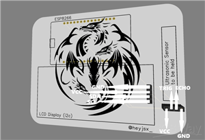
|
|
ESP8266 |
x 1 | |
|
|
LCD Display (i2C) |
x 1 | |
|
|
Ultrasonic Sensor |
x 1 |

|
KiCADKicad
|
|

|
arduino IDEArduino
|
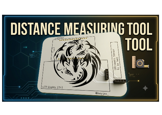
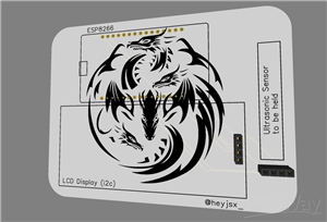
Distance Measuring Tool
# ESP8266 Distance Measurer - Complete Documentation
---
## 1. Project Overview
This is an ESP8266-based Distance Measurer that uses an HC-SR04 ultrasonic sensor to detect objects and display real-time distance readings on a 16x2 LCD screen. The system provides instant visual feedback of object proximity from 2cm to 400cm with an accuracy of ±0.3cm. The LCD continuously updates with distance measurements, making it ideal for robotics, parking assistance, industrial automation, and educational projects. The system can be extended with WiFi functionality for remote monitoring and data logging if needed.
---
## 2. Features
Real-time distance measurement from 2cm to 400cm with ±0.3cm accuracy. Live LCD display updates showing distance in centimeters. Built-in serial monitoring for debugging and data logging. Support for both I2C and standard 16x2 LCD modules. Simple plug-and-play operation with automatic continuous measurement. Optional WiFi connectivity for remote data access and logging. Low power consumption suitable for battery-powered applications. Compact design with minimal component requirements. Easy to modify and customize for various applications. No external power supply needed beyond USB or battery input.
---
## 3. Hardware Connections
### Pin Connection Diagram
ESP8266 Pin → Component Connection
D5 (GPIO14) → Ultrasonic Sensor TRIG Pin
D6 (GPIO12) → Ultrasonic Sensor ECHO Pin
VIN (5V Output) → Ultrasonic Sensor VCC (Red wire)
GND (Ground) → Ultrasonic Sensor GND (Black wire)
### For I2C LCD (Recommended - 4 wires)
D1 (GPIO5) → LCD SCL Pin (Clock)
D2 (GPIO4) → LCD SDA Pin (Data)
VIN (5V) or 3.3V → LCD VCC
GND → LCD GND
### For Standard LCD (16x2 - Without I2C)
D0 (GPIO16) → LCD RS Pin (Register Select)
D1 (GPIO5) → LCD EN Pin (Enable)
D2 (GPIO4) → LCD D4 Pin (Data Bit 4)
D3 (GPIO0) → LCD D5 Pin (Data Bit 5)
D4 (GPIO2) → LCD D6 Pin (Data Bit 6)
D7 (GPIO13) → LCD D7 Pin (Data Bit 7)
GND → LCD RW Pin (Read/Write - Connect to ground)
10K Potentiometer → LCD V0 Pin (Contrast adjust)
3.3V or 5V → LCD VDD and A (Backlight)
GND → LCD VSS and K (Backlight ground)
---
## 4. Software Requirements
### Required Libraries
LiquidCrystal_I2C by Frank de Brabander - Required for I2C LCD operation. Install through Arduino Library Manager.
LiquidCrystal - Built-in with Arduino IDE. Used for standard LCD without I2C.
ESP8266WiFi - Built-in with ESP8266 board package. Optional for WiFi functionality.
ESP8266WebServer - Built-in with ESP8266 board package. Optional for web server.
### Board Configuration
Board: NodeMCU 1.0 (ESP-12E Module) or Generic ESP8266 Module
Flash Size: 4MB
CPU Frequency: 80 MHz
Upload Speed: 115200
Port: Select your COM port (varies by system)
---
## 5. Installing Arduino IDE and Libraries
### Step 1: Install Arduino IDE
Download and install Arduino IDE from arduino.cc. Version 1.8.19 or later recommended. The IDE is available for Windows, Mac, and Linux operating systems.
### Step 2: Install ESP8266 Board Package
Open Arduino IDE and navigate to File then Preferences. In the Additional Boards Manager URLs field, add this URL: https://arduino.esp8266.com/stable/package_esp8266com_index.json
Go to Tools then Board then Boards Manager. Search for ESP8266 and install the package by Espressif Systems. This package provides all necessary tools to program ESP8266 boards.
### Step 3: Install Required Libraries
For I2C LCD: Go to Sketch then Include Library then Manage Libraries. Search for LiquidCrystal_I2C and install the version by Frank de Brabander.
For standard LCD: The LiquidCrystal library is already included with Arduino IDE and requires no installation.
For optional WiFi features: ESP8266WiFi and ESP8266WebServer libraries are included with the board package.
---
## 6. LCD Setup Configuration
### Finding I2C Address (For I2C LCD Only)
Upload an I2C scanner sketch to find your LCD address. Common addresses are 0x27 and 0x3F. Connect the LCD I2C pins to ESP8266 before scanning.
### Adjusting LCD Contrast (For Standard LCD Only)
Connect a 10K potentiometer to LCD V0 pin. Adjust the potentiometer until characters are clearly visible on the LCD. If using I2C LCD, contrast is fixed and requires no adjustment.
### Code Configuration
For I2C LCD, update this line with your correct address:
LiquidCrystal_I2C lcd(0x27, 16, 2); // Change 0x27 to 0x3F if needed
For standard LCD, update pin assignments if you use different pins:
LiquidCrystal lcd(RS, EN, D4, D5, D6, D7);
---
## 7. Code Configuration
### Basic Configuration
TRIG_PIN D5 - Ultrasonic trigger pin. ECHO_PIN D6 - Ultrasonic echo pin. These pins are fixed based on hardware connections.
### Measurement Settings
pulseIn(ECHO, HIGH, 30000) - Timeout in microseconds. 30000µs equals 30ms. Maximum range is approximately 400cm. Increase for longer range, decrease for faster response.
delay(500) - Update interval in milliseconds. Default is 500ms (0.5 seconds). Decrease for faster updates, increase to save power.
### Optional WiFi Configuration (If Enabled)
const char* ssid = "YOUR_WIFI_SSID"; - Your WiFi network name.
const char* password = "YOUR_WIFI_PASSWORD"; - Your WiFi password.
### LCD Display Format
The display shows "Distance:" on the first line. The second line shows the measured distance in centimeters or "Out of range!" if no object detected. The display clears previous text before updating to prevent ghosting.
---
## 8. How the System Works
### Ultrasonic Distance Measurement
The ultrasonic sensor measures distance by emitting a 40kHz sound wave and listening for its echo. The TRIG pin receives a 10-microsecond high pulse to trigger the burst. The sensor emits an ultrasonic pulse. The ECHO pin goes high immediately after the burst and stays high until the echo returns. The pulseIn function measures this duration. The duration in microseconds represents the round-trip time of the sound wave. The distance formula is: duration × 0.034 / 2 = distance in centimeters. The 0.034 factor represents the speed of sound in cm/µs at room temperature. Division by 2 accounts for the round trip (sound travels to object and back). The sensor provides readings from 2cm to 400cm with ±0.3cm accuracy.
### LCD Display Operation
The LCD operates in 4-bit mode to save GPIO pins. Characters are displayed using a 5x8 pixel matrix. The LiquidCrystal library handles all low-level communication. The I2C version uses only two data lines (SDA and SCL) plus power and ground. The standard version uses six data/control lines plus power and ground. Both versions update in real-time as measurements are taken. The display maintains the previous value while waiting for the next reading.
### Serial Communication
The Serial Monitor operates at 115200 baud. Each measurement is printed as "Distance: XX cm". This provides debug capability and data logging functionality. The serial output can be captured for analysis or used with other software.
---
## 9. System Workflow
Power on the ESP8266. The system initializes all GPIO pins. The LCD initializes and turns on the backlight. A startup message appears: "Distance Meter" on line 1 and "Initializing..." on line 2. After two seconds, the LCD clears. The main loop begins.
In the main loop, the trigger pin sends a 10µs pulse. The echo pin is read to measure pulse duration. The duration is converted to distance in centimeters. The LCD updates line 1 with "Distance:". Line 2 updates with the distance value or "Out of range!". The Serial Monitor prints the value for debugging. The system waits 500ms. The loop repeats continuously.
If WiFi is enabled (optional), the system connects to WiFi on startup. The web server starts hosting the distance page. Clients can view the current distance remotely.
---
## 10. Troubleshooting
### LCD Not Showing Text
If the LCD is blank, check power connections first. Ensure VCC and GND are properly connected. For standard LCD, adjust the contrast potentiometer until characters appear. For I2C LCD, verify the correct I2C address in code. Check that the backlight is enabled with lcd.backlight(). Ensure the LCD is properly initialized before writing text.
### I2C LCD Shows Blocks
If the I2C LCD shows solid blocks instead of text, the I2C address is incorrect. Run an I2C scanner sketch to find the correct address. Common addresses: 0x27 or 0x3F. Update the address in the code. Check SDA and SCL connections are secure. Ensure pull-up resistors are present (typically on I2C module).
### Distance Always 0
If distance always reads 0, check the ECHO pin connection. Ensure the ultrasonic sensor is receiving power. Verify the sensor is connected to the correct pins. Test the sensor with a simple sketch. Check that the ECHO pin is set as INPUT. Ensure the pulseIn function is not timing out.
### Distance Always Max
If distance always shows max or out of range, check the TRIG pin connection. Verify the TRIG pin is set as OUTPUT. Ensure the 10µs pulse is being sent. Check for loose connections. Test the sensor with a simple sketch. Verify no objects are too close to the sensor.
### Inconsistent Readings
If readings are inconsistent, add a 10µF capacitor between VCC and GND of the sensor. Ensure the sensor is mounted securely. Keep the sensor away from noise sources. Use shielded wires for long connections. Verify the power supply is stable. Add debouncing or averaging in code for smoother readings.
### Code Compilation Errors
If the code does not compile, ensure all required libraries are installed. Check the board is selected correctly. Verify the correct board package is installed. Check for missing semicolons or braces. Ensure library versions are compatible with ESP8266. Update all libraries to the latest versions.
### Serial Monitor Shows Garbage
If Serial Monitor shows garbage characters, check the baud rate. It should be set to 115200. Ensure the correct COM port is selected. Check the board is properly connected. Verify the board is not in a reset loop. Check power supply is sufficient.
### ESP8266 Not Connecting (WiFi)
If using WiFi features and the ESP8266 doesn't connect, check SSID and password are correct. Ensure the WiFi network is 2.4GHz (ESP8266 doesn't support 5GHz). Verify the router is within range. Check the antenna connection. Reset the router if necessary.
---
## 11. Configuration Parameters
### Pin Settings
TRIG_PIN D5 - Ultrasonic trigger output.
ECHO_PIN D6 - Ultrasonic echo input.
LCD address varies by module.
### Measurement Settings
pulseIn timeout: 30000µs (maximum range ~400cm).
Update delay: 500ms (adjustable between 100-2000ms).
Distance formula: duration × 0.034 / 2.
### LCD Settings
Rows: 2 lines.
Columns: 16 characters.
Backlight: ON (for I2C).
Contrast: Adjustable via potentiometer (standard LCD).
### Optional WiFi Settings
WiFi Mode: Station only (no AP fallback).
Web Server Port: 80.
Web Page Auto-refresh: 500ms.
---
## 12. Quick Reference
### Setup Steps Summary
Install Arduino IDE. Install ESP8266 board package. Install LiquidCrystal_I2C library (for I2C LCD). Connect hardware according to pin diagram. Update LCD address in code if using I2C. Upload code to ESP8266. Open Serial Monitor to verify readings. Adjust LCD contrast if needed.
### Common Commands
Serial Monitor baud rate: 115200.
pulseIn function: Measures echo duration in microseconds.
lcd.print: Displays text on LCD.
lcd.setCursor: Sets cursor position (column, row).
### Quick Troubleshooting
No LCD display: Check power and address/contrast.
No distance: Check sensor connections and pins.
Incorrect values: Add capacitor and verify power.
Compile errors: Check libraries and board selection.
---
## 13. Applications and Use Cases
### Robotics
Obstacle detection and avoidance for autonomous robots. Distance measurement for navigation and mapping. Proximity sensing for object manipulation. Collision prevention in automated systems.
### Parking Assistance
Vehicle parking distance indicators. Reverse parking sensors for cars. Garage parking alignment systems. Proximity warnings for tight spaces.
### Industrial Automation
Belt conveyor object detection. Level monitoring in tanks and silos. Material presence verification. Automated sorting and counting systems.
### Educational Projects
Physics experiments on sound wave propagation. Electronics learning and GPIO programming. Microcontroller sensor interfacing. Student projects in engineering courses.
### Home Automation
Door opening detection and alerts. Occupancy sensing for lighting control. Pet monitoring and tracking. Automated waste bin level monitoring.
---
## 14. Extension Possibilities
### WiFi Integration
Add remote monitoring through web browser. Send distance data to cloud services. Create mobile app for distance viewing. Enable data logging to SD card or cloud.
### Additional Sensors
Add temperature sensor to compensate for speed of sound variations. Include IR sensors for redundant detection. Add light sensor for ambient condition monitoring. Incorporate PIR sensor for motion detection.
### Display Enhancements
Use larger LCD or OLED displays for better visibility. Add graphical display showing distance as a bar graph. Include audible alerts with adjustable thresholds. Implement menu system for configuration.
### Power Optimization
Use deep sleep mode to extend battery life. Implement wake-on-change for events. Optimize measurement frequency for power saving. Use power-efficient components.
---
*Documentation Version: 1.0*
*Last Updated: 2026*
Distance Measuring Tool
Project images are for reference only. Actual production is based on the manufacturing files on the project page.
Please review the designer's notes (e.g., PCB thickness) and select the appropriate options.
PCBWay is not responsible
for issues caused by unsuitable parameter selections.
For more important ordering information, please refer to
Read More









Raspberry Pi 5 7 Inch Touch Screen IPS 1024x600 HD LCD HDMI-compatible Display for RPI 4B 3B+ OPI 5 AIDA64 PC Secondary Screen(Without Speaker)
BUY NOW


- Comments(0)
- Likes(0)
More by Heymant Visaakan J
-
 Automatic Barrier Controller
The Automatic Barrier Controller is a compact, single-PCB automated gate entry system designed for m...
Automatic Barrier Controller
The Automatic Barrier Controller is a compact, single-PCB automated gate entry system designed for m...
-
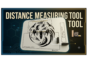 Distance Measuring Tool
# ESP8266 Distance Measurer - Complete Documentation---## 1. Project OverviewThis is an ESP8266-base...
Distance Measuring Tool
# ESP8266 Distance Measurer - Complete Documentation---## 1. Project OverviewThis is an ESP8266-base...
-
 Radar System
# ESP8266 Radar System - Complete Documentation---## 1. Project OverviewThis is an ESP8266-based Rad...
Radar System
# ESP8266 Radar System - Complete Documentation---## 1. Project OverviewThis is an ESP8266-based Rad...
-
 Desk Buddy
# Desk Buddy v2.0.0 - Complete Documentation---1. PROJECT OVERVIEWDesk Buddy v2.0.0 is a smart desk ...
Desk Buddy
# Desk Buddy v2.0.0 - Complete Documentation---1. PROJECT OVERVIEWDesk Buddy v2.0.0 is a smart desk ...
-
 Chess Clock
Project Overview:System Architecture & Control Logic:The ESP8266 acts as the central processor f...
Chess Clock
Project Overview:System Architecture & Control Logic:The ESP8266 acts as the central processor f...
-
 ESP32 Air Mouse
Project Overview:The ESP32 Air Mouse is an innovative, gesture-controlled mouse that lets you naviga...
ESP32 Air Mouse
Project Overview:The ESP32 Air Mouse is an innovative, gesture-controlled mouse that lets you naviga...
-
 Smart Clock
 PCB – Product DescriptionThe Smart Clock PCB is a custom-designed, 2-layer FR-4 printed ...
Smart Clock
Smart Clock PCB – Product DescriptionThe Smart Clock PCB is a custom-designed, 2-layer FR-4 printed ...
-
 Smart ThermoStat
Smart Thermostat using ESP8266 & Blynk IoT:This project is a Wi-Fi enabled smart thermostat buil...
Smart ThermoStat
Smart Thermostat using ESP8266 & Blynk IoT:This project is a Wi-Fi enabled smart thermostat buil...
-
Émetteur Récepteur Optique Expérimental (communication UART ATtiny + fibre optique)
140 0 1 -
SmallOLED - Live PC Stats, Animated Clocks & Audio Visualizer
990 0 3 -
"Talking Multimeter": Arduino-Based Speech Add-on for Multimeters with SCPI Protocol
566 0 1 -
Programmable Mist Maker - XIAO / QT PY Extension
3037 2 3 -
RadioHAT - Raspberry Pi radio development platform
2584 0 4 -
-
-