


|
|
NEO-6M-GPS |
x 1 | |
|
|
MPU-6050 |
x 1 | |
|
|
HMC5883L |
x 1 |

|
Soldering Iron Wire Welding Lead Roll |
|

|
Soldering iron |
|

|
arduino IDEArduino
|
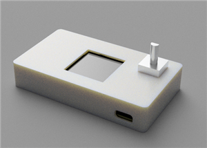
Positon Breakout Board
Position Sensors Breakout Board
In today's era of advanced technology, many electronics projects require an assortment of sensors to gather and process data for an array of applications.Featuring a GPS Module (u-blox NEO-6M), an Inertial Measurement Unit (IMU) (MPU-6050), and a 3-Axis Digital Compass Module (HMC5883L), this board facilitates seamless data collection from these distinct yet complementary sensors, unlocking a multitude of possibilities.
A Wide Spectrum of Applications:
- Global Positioning: The inclusion of the NEO-6M GPS Module allows for tracking the global position of objects with high accuracy. This feature proves indispensable in various applications such as vehicle tracking, asset management, and geofencing.
- Motion Tracking and Orientation: By utilizing the accelerometer and gyroscope of the MPU-6050, this breakout board can be deployed in projects that require motion tracking and orientation data. From creating an Inertial Measurement Unit (IMU) for drones to integrating into VR controllers, the applications are vast.
- Direction and Navigation: The HMC5883L's 3-axis digital compass data, coupled with the accelerometer and gyroscope data from the MPU-6050, can be used for building precise indoor and outdoor navigation systems. This combination can greatly enhance the capabilities of autonomous vehicles, wearables, or smartphone applications.
Developing the Breakout Board:
- Creating a professional and functional breakout board for position tracking requires a few steps:
- Collect the Required Materials: This includes a PCB board with pre-printed traces, the sensors (GPS module, IMU, and magnetometer), and other essentials such as a soldering iron, solder, flux, and cleaning supplies.
- Prepare the PCB Board: Clean the board using isopropyl alcohol and a lint-free cloth to ensure the proper adhesion of the components.
- Prepare and Place the Components: Inspect each component, straighten any bent pins, trim excess leads, and then place them on the PCB board, aligning the pins with the appropriate pads or holes.
- Soldering: Once the components are in place, solder each of them to the PCB board using a soldering iron. Ensure to achieve a shiny, concave fillet for each solder joint.
- Inspect the Solder Joints: Upon completion of soldering, examine each solder joint for any potential issues such as cold solder or solder bridges.
- Correct Any Soldering Issues: If any problems are found, they should be addressed immediately by reworking the solder joint.
- Clean the Assembled Board: After all components have been successfully soldered, clean the PCB board once more to remove flux residues.
- Test the Assembled Board: Connect the board to a power source and check each sensor for functionality.
- Program the Board: With the hardware part done, you can now upload Arduino codes to interact with the sensors, gather data, and perform further processing based on your project requirements.
Now your board should be ready for any application! The attached code can be used to test every sensor own the board and secure reliability.
// Include necessary libraries
#include <Wire.h>
#include <TinyGPS++.h>
#include <Adafruit_Sensor.h>
#include <Adafruit_HMC5883_U.h>

// Define GPS Module connections
#define RXPin 4
#define TXPin 3
#define GPSBaud 9600

// Create GPS object
TinyGPSPlus gps;
SoftwareSerial ss(RXPin, TXPin);

// Create magnetometer object
Adafruit_HMC5883_Unified mag = Adafruit_HMC5883_Unified(12345);

// MPU6050 object
#include <MPU6050.h>
MPU6050 mpu;

void setup() {
  // Start communication with devices
  Wire.begin();
  ss.begin(GPSBaud);
  Serial.begin(115200);

  // Initialise the magnetometer
  if(!mag.begin()) {
    Serial.println("Failed to initialize magnetometer");
    while(1);
  }

  // Initialise the MPU6050
  mpu.initialize();
  if(!mpu.testConnection()) {
    Serial.println("Failed to initialize MPU6050");
    while(1);
  }
}

void loop() {
  // Read from GPS
  while (ss.available() > 0) {
    gps.encode(ss.read());
    if (gps.location.isUpdated()) {
      Serial.print("Latitude= ");
      Serial.print(gps.location.lat(), 6);
      Serial.print(" Longitude= ");
      Serial.println(gps.location.lng(), 6);
    }
  }

  // Read from magnetometer
  sensors_event_t event;
  mag.getEvent(&event);
  Serial.print("Magnetic X: "); Serial.print(event.magnetic.x); Serial.print(" ");
  Serial.print("Y: "); Serial.print(event.magnetic.y); Serial.print(" ");
  Serial.print("Z: "); Serial.print(event.magnetic.z); Serial.print(" ");
  Serial.println("uT");

  // Read from MPU6050
  int16_t ax, ay, az, gx, gy, gz;
  mpu.getMotion6(&ax, &ay, &az, &gx, &gy, &gz);
  Serial.print("Acceleration X: "); Serial.print(ax); Serial.print(" ");
  Serial.print("Y: "); Serial.print(ay); Serial.print(" ");
  Serial.print("Z: "); Serial.print(az); Serial.print(" ");
  Serial.print("Gyro X: "); Serial.print(gx); Serial.print(" ");
  Serial.print("Y: "); Serial.print(gy); Serial.print(" ");
  Serial.print("Z: "); Serial.print(gz); Serial.println(" ");

  // Delay for readability of output
  delay(1000);
}
Positon Breakout Board
*PCBWay community is a sharing platform. We are not responsible for any design issues and parameter issues (board thickness, surface finish, etc.) you choose.


Raspberry Pi 5 7 Inch Touch Screen IPS 1024x600 HD LCD HDMI-compatible Display for RPI 4B 3B+ OPI 5 AIDA64 PC Secondary Screen(Without Speaker)
BUY NOW


- Comments(0)
- Likes(0)
More by Inaki Iturriaga
-
 Battery-Powered ESP32-CAM Continuous Video Recorder
OverviewThis project transforms an ESP32-CAM module into a standalone, battery-powered video recordi...
Battery-Powered ESP32-CAM Continuous Video Recorder
OverviewThis project transforms an ESP32-CAM module into a standalone, battery-powered video recordi...
-
 GPS Mobile Beacon
Building a GPS Emergency Beacon: A DIY TutorialWelcome to our latest DIY project: creating a GPS Eme...
GPS Mobile Beacon
Building a GPS Emergency Beacon: A DIY TutorialWelcome to our latest DIY project: creating a GPS Eme...
-
 Wireless RFID Card Copier.
Wireless RFID Card CopierIn today's digital world, security and accessibility are of paramount impor...
Wireless RFID Card Copier.
Wireless RFID Card CopierIn today's digital world, security and accessibility are of paramount impor...
-
 Piezo Alert System.
Within the fast-evolving sphere of security tools and home automation, creativity often paves the wa...
Piezo Alert System.
Within the fast-evolving sphere of security tools and home automation, creativity often paves the wa...
-
 Wifi Weather Station - Sensors board
WiFi Weather Station - Sensor unitIn our digital era, many electronics projects integrate diverse se...
Wifi Weather Station - Sensors board
WiFi Weather Station - Sensor unitIn our digital era, many electronics projects integrate diverse se...
-
 Building a GPS Speedometer with RP2040-Zero
Build a Feature-Packed GPS Speedometer with an RP2040This project guide will walk you through buildi...
Building a GPS Speedometer with RP2040-Zero
Build a Feature-Packed GPS Speedometer with an RP2040This project guide will walk you through buildi...
-
 RC Receiver
Build Your Own RC ReceiverHarnessing advanced electronics and precise control systems, the RC Receiv...
RC Receiver
Build Your Own RC ReceiverHarnessing advanced electronics and precise control systems, the RC Receiv...
-
 Universal RC Controller
Build Your Own Universal RC RemoteHarnessing the power of custom PCBs and wireless communication, th...
Universal RC Controller
Build Your Own Universal RC RemoteHarnessing the power of custom PCBs and wireless communication, th...
-
 Continuous GPS Tracker
This compact and efficient tracker provides real-time location updates, making it ideal for surveill...
Continuous GPS Tracker
This compact and efficient tracker provides real-time location updates, making it ideal for surveill...
-
 Air Quality Monitor
Welcome to our DIY tutorial on assembling an Air Quality Monitoring Device. This project is perfect ...
Air Quality Monitor
Welcome to our DIY tutorial on assembling an Air Quality Monitoring Device. This project is perfect ...
-
 Automatic Watch Winder
In the realm of luxury timepieces and watch aficionados, an automatic watch is...
Automatic Watch Winder
Automatic Watch WinderIn the realm of luxury timepieces and watch aficionados, an automatic watch is...
-
 Handheld GPS
Within the swiftly advancing realm of portable technology and travel essentials, innovation often sh...
Handheld GPS
Within the swiftly advancing realm of portable technology and travel essentials, innovation often sh...
-
 Dual Motor Controller for Model Robotics
In the thrilling world of robotics and DIY engineering, innovation continues to soar to new heights....
Dual Motor Controller for Model Robotics
In the thrilling world of robotics and DIY engineering, innovation continues to soar to new heights....
-
 Altitude Indicator with Beeper for Rocketry
Altitude Indicator for Model RocketryIn our ever-advancing technological landscape, countless projec...
Altitude Indicator with Beeper for Rocketry
Altitude Indicator for Model RocketryIn our ever-advancing technological landscape, countless projec...
-
 Wifi Weather Station - Display unit
WiFi Weather Station - Display UnitIn this technologically advanced age, countless electronics proje...
Wifi Weather Station - Display unit
WiFi Weather Station - Display UnitIn this technologically advanced age, countless electronics proje...
-
 Positon Breakout Board
Position Sensors Breakout Board In today's era of advanced technology, many electronics projects req...
Positon Breakout Board
Position Sensors Breakout Board In today's era of advanced technology, many electronics projects req...
-
 Ambient Sensors Breakout Board
In today's world, electronics projects often require the integration of multiple sensors to collect ...
Ambient Sensors Breakout Board
In today's world, electronics projects often require the integration of multiple sensors to collect ...
-
 Infrared Launch Controller
IntroductionHave you ever wanted to remotely launch a rocket, drone or other device using infrared t...
Infrared Launch Controller
IntroductionHave you ever wanted to remotely launch a rocket, drone or other device using infrared t...
-
Programmable Mist Maker - XIAO / QT PY Extension
413 0 0 -
RadioHAT - Raspberry Pi radio development platform
322 0 1 -
-
-
-
-
ARPS-2 – Arduino-Compatible Robot Project Shield for Arduino UNO
2875 0 6 -
A Compact Charging Breakout Board For Waveshare ESP32-C3
3377 3 8 -
AI-driven LoRa & LLM-enabled Kiosk & Food Delivery System
3695 2 2


