


|
|
TSOP4838VISHAY(威世)
|
x 1 | |
|
|
Arduino_UNO_R3 |
x 1 | |
|
|
LED-WHITE3014 |
x 1 |
IR Remote Tester and Decoder
Intro
What do you generally do when your remote controls starts playing up?
- Do you generally use a multimeter and check the voltage and current produced by the battery?
- Or do you point the remote control to a digital camera and try to visualize the infrared light?
In this video, I am going to show you guys how to create a simple InfraRed(IR) Receiver Circuit using TSOP4838 and will also show you how to read the code send by the remote controls. You can also use this circuit as an IR remote tester.
Setup Without Arduino

Lets first have a look at the setup without an Arduino.
The main component of this circuit is the Infrared Remote (IR) Receiver TSOP4838.
The TSOP4838 is tuned to 38kHz, which is typically the frequency range of the TV remote controls.
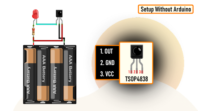
From left to right Pin-1 is the OUTput pin, Pin-2 is GND and Pin-3 is VCC. Just remember, the pin assignments can be different depending upon the TSOP variant. So, please be very careful while hooking it up to your circuit.
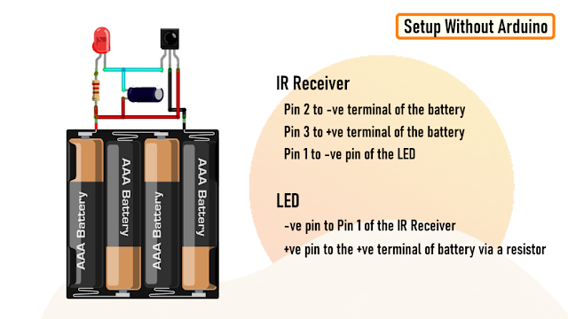
Now, lets have a look at the setup.
Connect Pin-2 of IR Receiver to the -ve and Pin-3 to the +ve terminal of the battery.
Then connect the -ve pin of the LED to Pin-1 of the IR Receiver and the +ve pin to the +ve terminal of the battery by placing a current limiting resistance in-between.
To reduce the flickering rate of the LED, you can add a capacitor anything between 10mfd to 100mfd between Pin-3 and VCC of the circuit.
That's it, as easy as that.
Demo Without Arduino
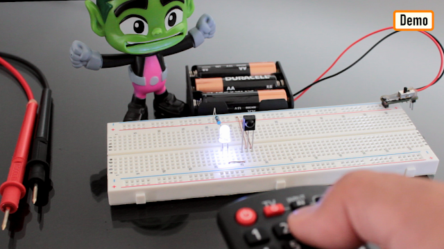
Now, lets do a quick test.
As you can see, when I press any button on the the remote control the LED starts flickering.
TSOP4838 demodulates the signals received from the remote control and gives the output in the form of active low to the LED.
Adding a capacitor will lower the flickering rate of the LED.
The supply voltage has to be strictly between 5V-6V.
Setup Using Arduino

Now, lets set this up using a MicroController and try to read the demodulated signals.
Connect the +ve pin of the IR Receiver to 5V, -ve to GND and the OUT pin to Pin-2 of the Arduino.
You can also add the optional LED to this setup to get a visual effect when the Receiver decodes the signal.

The Code
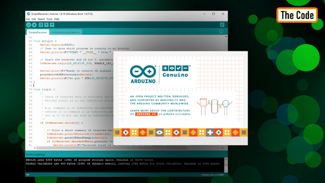
Now, go ahead and launch Arduino IDE and go to "Tools" > "Manage Libraries".
Download and Install the latest release of the "IRremote" library from the library manager.
Then, go to "Examples" and open the "SimpleReceiver" example. Go ahead and load the code without making any modification to the Arduino Board.
Demo Using Arduino

For this demo, I am using a Panasonic and a Sony remote control. The decoded data will be shown using the Arduino IDE's Serial Monitor.
As you can see when I press a button on the remote control, the LED lights up and the decoded data is displayed on the serial monitor.

The serial monitor displays a lot of information, but the one of my interest is the "Source" and the "Command" send by the remote control.
Uses
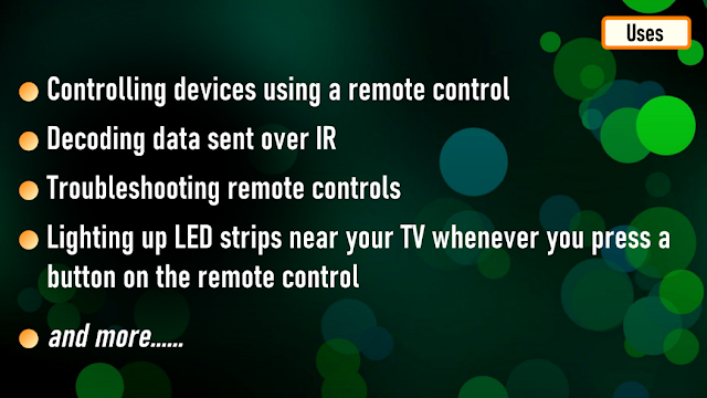
Some common uses of this project includes:
Controlling devices using a remote control
Decoding data sent over IR
Troubleshooting remote controls
Lighting up LED strips near your TV whenever you press a button on the remote control
Thanks
Thanks again for checking my post. I hope it helps you.
If you want to support me subscribe to my YouTube Channel: https://www.youtube.com/user/tarantula3
Video: Video Link
Full Blog Post: Blog Post
Datasheet: Download
Support My Work:
- BTC: 15cNh9hup8jidCVPwa1DTcxeoh2FPijVrX
- LTC: LbquH9Ku78vHtcm3LZnWXpD1JQWdKzeV4v
- DOGE: DEB2QBAihnBRhGsaB8P7kz559TDiucQhX6
- ETH: 0x5d8c9ba0e54d8354d4af81871db26daa190d2194
- BAT: 0x939aa4e13ecb4b46663c8017986abc0d204cde60
- LBC: bZ8ANEJFsd2MNFfpoxBhtFNPboh7PmD7M2
- COS: bnb136ns6lfw4zs5hg4n85vdthaad7hq5m4gtkgf23 Memo: 572187879
- BNB: 0x5d8c9ba0e54d8354d4af81871db26daa190d2194
Thanks, ca again in my next tutorial.
IR Remote Tester and Decoder


Raspberry Pi 5 7 Inch Touch Screen IPS 1024x600 HD LCD HDMI-compatible Display for RPI 4B 3B+ OPI 5 AIDA64 PC Secondary Screen(Without Speaker)
BUY NOW


- Comments(0)
- Likes(2)
More by Ashish Adhikari
-
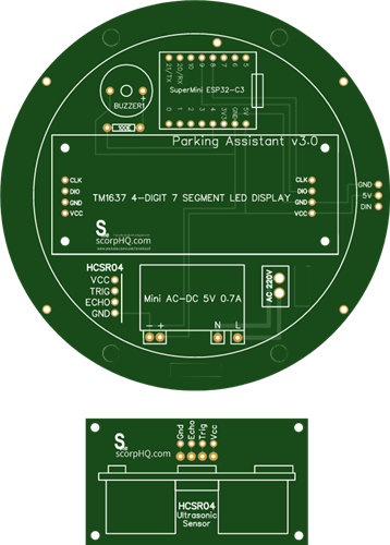 Arduino Parking Assistant V3
The ESP32-C3 Based Parking Assistant is an advanced parking sensor system that utilizes the ESP32-C3...
Arduino Parking Assistant V3
The ESP32-C3 Based Parking Assistant is an advanced parking sensor system that utilizes the ESP32-C3...
-
 100 LED Chaser Circuit Using IC555 and CD4017
A Chaser Circuit consists of a clocked IC or other electronic unit like an Arduino that drives an ar...
100 LED Chaser Circuit Using IC555 and CD4017
A Chaser Circuit consists of a clocked IC or other electronic unit like an Arduino that drives an ar...
-
 Cute Medusa 3D Printed Humidifier
Humidifiers add moisture to the air. They can help people with dry skin, allergies, and respiratory ...
Cute Medusa 3D Printed Humidifier
Humidifiers add moisture to the air. They can help people with dry skin, allergies, and respiratory ...
-
 4x4x4 PCB LED CUBE
Note from PCBWay: This project includes two PCBs, if both need to be produced, please inform your sa...
4x4x4 PCB LED CUBE
Note from PCBWay: This project includes two PCBs, if both need to be produced, please inform your sa...
-
 Getting Started With Raspberry Pi Pico
Couple of months ago, I bought a "Raspberry Pi Pico" to get some hands-on experience of it and to cr...
Getting Started With Raspberry Pi Pico
Couple of months ago, I bought a "Raspberry Pi Pico" to get some hands-on experience of it and to cr...
-
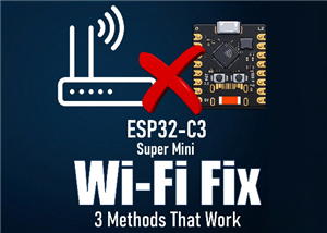 ESP32 C3 Super Mini WiFi Fix - 3 Methods That Work
Hi everyone! I’ve recently started working with a tiny, super affordable microcontroller board calle...
ESP32 C3 Super Mini WiFi Fix - 3 Methods That Work
Hi everyone! I’ve recently started working with a tiny, super affordable microcontroller board calle...
-
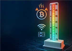 Programmable RGB Thermometer
Summer has been relentless this year. My passion for Bitcoin mining took a major hit due to the imme...
Programmable RGB Thermometer
Summer has been relentless this year. My passion for Bitcoin mining took a major hit due to the imme...
-
 All About PC817 Optocoupler
An Optocoupler also known as Photocoupler or Optical Isolator is a component that transfers electric...
All About PC817 Optocoupler
An Optocoupler also known as Photocoupler or Optical Isolator is a component that transfers electric...
-
 Make Your Own 3D Printed Diwali Diyas at Home
Diyas are the heart of major Indian festivals, most notably Diwali, the "Festival of Lights." Lighti...
Make Your Own 3D Printed Diwali Diyas at Home
Diyas are the heart of major Indian festivals, most notably Diwali, the "Festival of Lights." Lighti...
-
 Arduino Based 3D Printed Color Adjustable Minecraft Lantern
For this Halloween, I'm fusing the creative blocky world of Minecraft with the spooky glow of the co...
Arduino Based 3D Printed Color Adjustable Minecraft Lantern
For this Halloween, I'm fusing the creative blocky world of Minecraft with the spooky glow of the co...
-
 3D Printed Breathing IC555 LED Trophy
This project features a custom 3D-printed 'Mortal Kombat' trophy shell paired with a basic NE555 tim...
3D Printed Breathing IC555 LED Trophy
This project features a custom 3D-printed 'Mortal Kombat' trophy shell paired with a basic NE555 tim...
-
 Destiny Internet Ghost - Internet Notifier
The Internet has changed the way we live our lives. From communication, education, banking, entertai...
Destiny Internet Ghost - Internet Notifier
The Internet has changed the way we live our lives. From communication, education, banking, entertai...
-
 Liquid level indicator Using ULN2003
A water level indicator detects and indicates the level of water in an overhead tank and relays the ...
Liquid level indicator Using ULN2003
A water level indicator detects and indicates the level of water in an overhead tank and relays the ...
-
 All About IC UNL2003
The UNL2003 IC contains 7 High Voltage, High Current NPN Darlington Transistor Arrays each rated at ...
All About IC UNL2003
The UNL2003 IC contains 7 High Voltage, High Current NPN Darlington Transistor Arrays each rated at ...
-
 NodeMCU Based: 3D Printed Indoor Gauge Thermometer
Had some time this weekend and a desire to create something new and interesting, so went ahead and c...
NodeMCU Based: 3D Printed Indoor Gauge Thermometer
Had some time this weekend and a desire to create something new and interesting, so went ahead and c...
-
 Rechargeable Gothic Lantern
A Gothic Lantern is a captivating piece of lighting that brings the allure of the Victorian Era into...
Rechargeable Gothic Lantern
A Gothic Lantern is a captivating piece of lighting that brings the allure of the Victorian Era into...
-
 555 Adjustable Delay On Off Timer Circuit
The 555 timer IC is an integrated circuit (IC) that is used in a variety of timer, delay, pulse gene...
555 Adjustable Delay On Off Timer Circuit
The 555 timer IC is an integrated circuit (IC) that is used in a variety of timer, delay, pulse gene...
-
 3D Printed Arduino Halloween Décor
When the full moon is shining and the wolves are howling, it's time for Halloween's spooky spectacle...
3D Printed Arduino Halloween Décor
When the full moon is shining and the wolves are howling, it's time for Halloween's spooky spectacle...
-
Programmable Mist Maker - XIAO / QT PY Extension
399 0 0 -
RadioHAT - Raspberry Pi radio development platform
313 0 1 -
-
-
-
-
ARPS-2 – Arduino-Compatible Robot Project Shield for Arduino UNO
2865 0 6 -
A Compact Charging Breakout Board For Waveshare ESP32-C3
3368 3 8 -
AI-driven LoRa & LLM-enabled Kiosk & Food Delivery System
3685 2 2


