


|
Autodesk Fusion 360Autodesk
|
Focus Stacking Mechanism
In my previous project, I shared the PCB for this mechanism. In this project, I share the parts of the linear actuator that I designed for focus stacking.
The mechanism's base is a 250 mm long 2080 aluminium extrusion profile. I picked this part because it is stiff, it is easy to source, it is cheap, and it is very easy to attach things to it.
The mechanism is driven by a NEMA 17 stepper motor. The motor is mounted at the end of this 250 mm long profile by a bracket that I designed for this purpose using four M3x10 bolts. The bracket is attached to the 2080 profile by four M4x10 bolts and corresponding T-nuts.
Continuing the chain from the motor, there is a 5 mm to 8 mm flexible coupler. This allows the power transmission between the shaft of the stepper motor and the lead screw. The lead screw is an 8 mm diameter, 200 mm long and 1 mm pitch version. The 1 mm pitch provides quite a small step size even when the motor is at the full step (1.8° / step) setting: 5 micrometres. Further increasing the microstepping, the theoretical step size can be brought below a micrometre. The lead screw drives a spring-loaded anti-backlash nut. The anti-backlash nut has tightly spaced holes, so I just directly screwed M3 bolts in the holes on the 3d-printed crosshead.
The lead screw is supported by two KFL08 flange bearings. The bearings are held by custom-designed 3d-printed supports at each end of the linear rails. I designed these pieces so they fit the 2080 profile perfectly. The supports are attached to the 2080 profile by 4 screws each. Two from each side of the profile (M4x15 hex), and two from the top (M4x10 hex). The bearings can be attached to the supports in two different ways: either by pressing the M4 insert nut in the holes and attaching the bearings to these insert nuts (I used this method) or by using longer M4 or M5 bolts that go through the whole support. In this case, at least 22 mm long bolts should be used.
Parallel with the lead screw, there is a linear guide rail on each side of the screw. Both rails are 8 mm in diameter and 200 mm long. These guides snap in their holes in the supports, there is no need for adhesives or bolts...etc.
Finally, these guides support a so-called crosshead. This crosshead has the anti-backlash nut fitted in it and it is driven by the lead screw. It also has two Drylin Igus linear sliding bearings to support the linear shafts. The crosshead can be closed by a cap after inserting the Drylin bearings. There are four holes around the bearings on each side for tightly attaching the cap to the crosshead.
There are four, 5 mm diameter holes on the top of the crosshead. They support the mounting plate for the camera quick-release plate. You can use 4 mm insert nuts in these four holes, or directly use 5 mm bolts. As you turn them in the holes, they will cut the thread for themselves. The holder for the quick-release plate has a 6 mm hole in its centre. I directly bolted an M6 bolt in the hole (1/4" camera bolt also works).
2023-04-10 Update:
I designed an attachment for the already existing rig so it can be used in a vertical alignment too. The attachment requires the following components:
- a 250 mm long 2040 aluminium profile,
- two, 250 mm long 2020 aluminium profiles,
- twenty pieces of M5 bolts (10 mm thread length), M5 T-nuts, and washers
- three, 3D printable parts that can be found below
- 2040_clamp_closedEnd-STL
- 2040_clamp_openEnd-STL
- centerPiece-STL
The holes on the pieces might run a bit tight, so it is recommended to ream the holes with a 5 mm drill bit. In my test, the vertical rig was able to move a load of 3119 grams upwards while maintaining 10 um step size consistently.
Focus Stacking Mechanism
*PCBWay community is a sharing platform. We are not responsible for any design issues and parameter issues (board thickness, surface finish, etc.) you choose.


Raspberry Pi 5 7 Inch Touch Screen IPS 1024x600 HD LCD HDMI-compatible Display for RPI 4B 3B+ OPI 5 AIDA64 PC Secondary Screen(Without Speaker)
BUY NOW


- Comments(10)
- Likes(5)
 More by Curious Scientist
-
 USB PD Breadboard Power Supply
In this article, I show you my new creation. It is a USB PD decoy-based breadboard power supply. All...
USB PD Breadboard Power Supply
In this article, I show you my new creation. It is a USB PD decoy-based breadboard power supply. All...
-
 ADS1256 - RP2040 Custom DAQ Front Panel with GPIO
This is just a simple PCB panel that belongs to my other project which is a high-performance DAQ.A r...
ADS1256 - RP2040 Custom DAQ Front Panel with GPIO
This is just a simple PCB panel that belongs to my other project which is a high-performance DAQ.A r...
-
 ADS1256 - RP2040 Custom DAQ Front Panel without GPIO
This is just a simple PCB panel that belongs to my other project which is a high-performance DAQ.A r...
ADS1256 - RP2040 Custom DAQ Front Panel without GPIO
This is just a simple PCB panel that belongs to my other project which is a high-performance DAQ.A r...
-
 10th Anniversary Badge
I designed this small badge for PCBWay's 10th anniversary.I tried to make a deeper meaning to the bo...
10th Anniversary Badge
I designed this small badge for PCBWay's 10th anniversary.I tried to make a deeper meaning to the bo...
-
 ADS1256 - Atmega32u4 Custom DAQ board
IntroductionIn this project, I show you two things. One is a new version (v1.2) of my custom DAQ bas...
ADS1256 - Atmega32u4 Custom DAQ board
IntroductionIn this project, I show you two things. One is a new version (v1.2) of my custom DAQ bas...
-
 Debounced rotary encoder module
In this project, I show you my approach to making a rotary encoder module.One can buy different rota...
Debounced rotary encoder module
In this project, I show you my approach to making a rotary encoder module.One can buy different rota...
-
 Custom ADS1256 board with ATmega32U4
I created my own ADS1256 PCB after working with this AD converter for several years. I wanted to bui...
Custom ADS1256 board with ATmega32U4
I created my own ADS1256 PCB after working with this AD converter for several years. I wanted to bui...
-
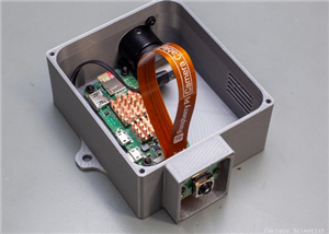 Raspberry Pi Zero 2W Bird Feeder Camera
In this article, I show you how I built my own Raspberry Pi Zero 2 W-based bird camera. The project ...
Raspberry Pi Zero 2W Bird Feeder Camera
In this article, I show you how I built my own Raspberry Pi Zero 2 W-based bird camera. The project ...
-
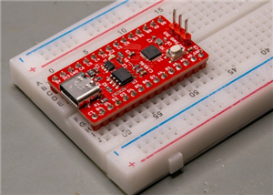
 CH32V003J4M6 - Miniature microcontroller board
I wanted something small but relatively capable, and since I have some experience with the CH32V003J...
CH32V003J4M6 - Miniature microcontroller board
I wanted something small but relatively capable, and since I have some experience with the CH32V003J...
-
 3-axis stepper motor controller with CNC pendant connectivity
In this article, I show you the updated version of my motorized microscope. In one of my older video...
3-axis stepper motor controller with CNC pendant connectivity
In this article, I show you the updated version of my motorized microscope. In one of my older video...
-
 Light meter for analog cameras [CH32V006F8P6 + TSL2591]
In this article, I show you how I built my ow...
Light meter for analog cameras [CH32V006F8P6 + TSL2591]
Light meter for analog cameras [CH32V006F8P6 + TSL2591]In this article, I show you how I built my ow...
-
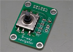 5-way navigator PCB
In this article, I show you a genius way of handling multiple buttons with a microcontroller. I “dis...
5-way navigator PCB
In this article, I show you a genius way of handling multiple buttons with a microcontroller. I “dis...
-
 CH32V006K8U6 Development Board
IntroductionSo, I have been working with the CH32 microcontrollers and chips for a while, and I even...
CH32V006K8U6 Development Board
IntroductionSo, I have been working with the CH32 microcontrollers and chips for a while, and I even...
-
 PCBWay 11-year Anniversary Badge
This visual design was created by https://www.instagram.com/guiye.perez.bongiovanni/ ; however, only...
PCBWay 11-year Anniversary Badge
This visual design was created by https://www.instagram.com/guiye.perez.bongiovanni/ ; however, only...
-
 TCD1304 - STM32F401CCU6 breakout board
The recent modifications made to the circuit board design have improved its functionality and space ...
TCD1304 - STM32F401CCU6 breakout board
The recent modifications made to the circuit board design have improved its functionality and space ...
-
 TCD1304 miniature PCB rev2
The redesign of the PCB involved several key changes to improve its performance and decrease its siz...
TCD1304 miniature PCB rev2
The redesign of the PCB involved several key changes to improve its performance and decrease its siz...
-
 2-channel breadboard voltmeter
The project originally stems from my CH32 tutorial series. I started working with this chip not so l...
2-channel breadboard voltmeter
The project originally stems from my CH32 tutorial series. I started working with this chip not so l...
-
 ADS1256 - RP2040 Custom DAQ Rear Panel
This is just a simple PCB panel that belongs to my other project which is a high-performance DAQ.A r...
ADS1256 - RP2040 Custom DAQ Rear Panel
This is just a simple PCB panel that belongs to my other project which is a high-performance DAQ.A r...
-
Programmable Mist Maker - XIAO / QT PY Extension
172 0 0 -
RadioHAT - Raspberry Pi radio development platform
182 0 1 -
-
-
-
-
ARPS-2 – Arduino-Compatible Robot Project Shield for Arduino UNO
2767 0 5 -
A Compact Charging Breakout Board For Waveshare ESP32-C3
3275 3 8 -
AI-driven LoRa & LLM-enabled Kiosk & Food Delivery System
3530 2 2


