


|
KiCad 8.0KiCad
|
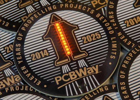
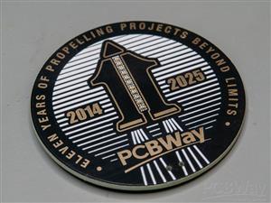
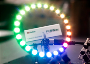
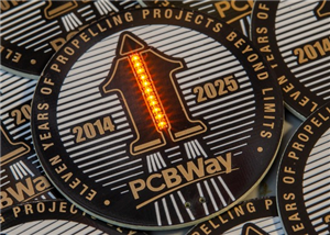
PCBWay 11-year Anniversary Badge
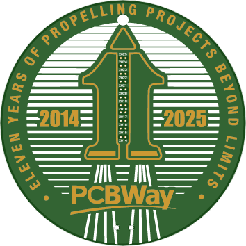
This visual design was created by https://www.instagram.com/guiye.perez.bongiovanni/ ; however, only the graphical part. The sketch of the electrical design had several mistakes in it, and it was incomplete.
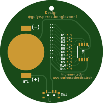
I got the task to turn the visual design into a working badge and circuit. So, based on the graphical elements and a simple Arduino source code (originally with Spanish comments) I had to come up with a design in KiCAD.
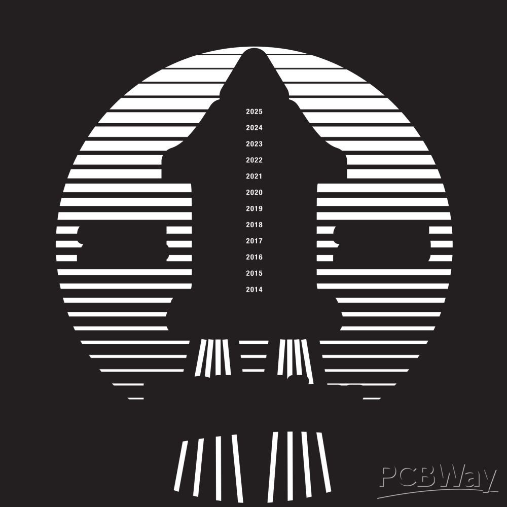
First, I reverse-engineered the circuit and fixed the design issues. Then I created the corresponding footprints from the two main graphical elements, which are the front silk screen and the front mask. The front silk screen was straightforward since it was just a simple silk screen print in white colour. The front mask was a bit different because, according to the design, it had to have a golden colour. This is achieved by exposing the copper on the front layer by placing the mask layer over a copper layer and assigning immersion gold (ENIG) surface finish to the board when ordering.
When you upload the code for the ATtiny85, first, you need to burn the bootloader on the chip. The clock source has to be selected as "Internal 16 MHz". After the bootloader has been successfully burned on the chip, upload the code as usual.
// Pins where the LED pairs are connected
const int ledPins[] = {0, 1, 2, 4, 3};
const int numSteps = sizeof(ledPins) / sizeof(ledPins[0]);

void setup() {
  // Configure each pin as output and turn off LEDs at the beginning
  for (int i = 0; i < numSteps; i++) {
    pinMode(ledPins[i], OUTPUT);
    digitalWrite(ledPins[i], HIGH); // HIGH = OFF since LEDs are connected to V+ and sink to MCU
  }
}

void loop() {
  // ---- Animation 1: Turns on one by one, then turns off ----
  for (int i = 0; i < numSteps; i++) {
    digitalWrite(ledPins[i], LOW);  // Turn on LED (sink current)
    delay(1000);
    digitalWrite(ledPins[i], HIGH); // Turn off LED
  }

  delay(800); // Pause between animations

  // ---- Animation 2: Turns on one by one and stays on ----
  for (int i = 0; i < numSteps; i++) {
    digitalWrite(ledPins[i], LOW);  // Turn on LED
    delay(700);
  }

  delay(1500); // Pause while all LEDs are on

  // Turn off all LEDs together
  for (int i = 0; i < numSteps; i++) {
    digitalWrite(ledPins[i], HIGH); // Turn off LED
  }

  delay(1000); // Pause before repeating
}
PCBWay 11-year Anniversary Badge
*PCBWay community is a sharing platform. We are not responsible for any design issues and parameter issues (board thickness, surface finish, etc.) you choose.


Raspberry Pi 5 7 Inch Touch Screen IPS 1024x600 HD LCD HDMI-compatible Display for RPI 4B 3B+ OPI 5 AIDA64 PC Secondary Screen(Without Speaker)
BUY NOW


- Comments(2)
- Likes(0)
 More by Curious Scientist
-
 USB PD Breadboard Power Supply
In this article, I show you my new creation. It is a USB PD decoy-based breadboard power supply. All...
USB PD Breadboard Power Supply
In this article, I show you my new creation. It is a USB PD decoy-based breadboard power supply. All...
-
 ADS1256 - RP2040 Custom DAQ Front Panel with GPIO
This is just a simple PCB panel that belongs to my other project which is a high-performance DAQ.A r...
ADS1256 - RP2040 Custom DAQ Front Panel with GPIO
This is just a simple PCB panel that belongs to my other project which is a high-performance DAQ.A r...
-
 ADS1256 - RP2040 Custom DAQ Front Panel without GPIO
This is just a simple PCB panel that belongs to my other project which is a high-performance DAQ.A r...
ADS1256 - RP2040 Custom DAQ Front Panel without GPIO
This is just a simple PCB panel that belongs to my other project which is a high-performance DAQ.A r...
-
 10th Anniversary Badge
I designed this small badge for PCBWay's 10th anniversary.I tried to make a deeper meaning to the bo...
10th Anniversary Badge
I designed this small badge for PCBWay's 10th anniversary.I tried to make a deeper meaning to the bo...
-
 ADS1256 - Atmega32u4 Custom DAQ board
IntroductionIn this project, I show you two things. One is a new version (v1.2) of my custom DAQ bas...
ADS1256 - Atmega32u4 Custom DAQ board
IntroductionIn this project, I show you two things. One is a new version (v1.2) of my custom DAQ bas...
-
 Debounced rotary encoder module
In this project, I show you my approach to making a rotary encoder module.One can buy different rota...
Debounced rotary encoder module
In this project, I show you my approach to making a rotary encoder module.One can buy different rota...
-
 Custom ADS1256 board with ATmega32U4
I created my own ADS1256 PCB after working with this AD converter for several years. I wanted to bui...
Custom ADS1256 board with ATmega32U4
I created my own ADS1256 PCB after working with this AD converter for several years. I wanted to bui...
-
 Raspberry Pi Zero 2W Bird Feeder Camera
In this article, I show you how I built my own Raspberry Pi Zero 2 W-based bird camera. The project ...
Raspberry Pi Zero 2W Bird Feeder Camera
In this article, I show you how I built my own Raspberry Pi Zero 2 W-based bird camera. The project ...
-
 CH32V003J4M6 - Miniature microcontroller board
I wanted something small but relatively capable, and since I have some experience with the CH32V003J...
CH32V003J4M6 - Miniature microcontroller board
I wanted something small but relatively capable, and since I have some experience with the CH32V003J...
-
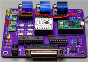 3-axis stepper motor controller with CNC pendant connectivity
In this article, I show you the updated version of my motorized microscope. In one of my older video...
3-axis stepper motor controller with CNC pendant connectivity
In this article, I show you the updated version of my motorized microscope. In one of my older video...
-
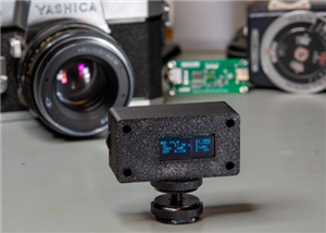 Light meter for analog cameras [CH32V006F8P6 + TSL2591]
In this article, I show you how I built my ow...
Light meter for analog cameras [CH32V006F8P6 + TSL2591]
Light meter for analog cameras [CH32V006F8P6 + TSL2591]In this article, I show you how I built my ow...
-
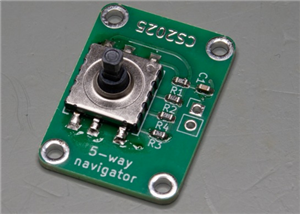 5-way navigator PCB
In this article, I show you a genius way of handling multiple buttons with a microcontroller. I “dis...
5-way navigator PCB
In this article, I show you a genius way of handling multiple buttons with a microcontroller. I “dis...
-
 CH32V006K8U6 Development Board
IntroductionSo, I have been working with the CH32 microcontrollers and chips for a while, and I even...
CH32V006K8U6 Development Board
IntroductionSo, I have been working with the CH32 microcontrollers and chips for a while, and I even...
-
 PCBWay 11-year Anniversary Badge
This visual design was created by https://www.instagram.com/guiye.perez.bongiovanni/ ; however, only...
PCBWay 11-year Anniversary Badge
This visual design was created by https://www.instagram.com/guiye.perez.bongiovanni/ ; however, only...
-
 TCD1304 - STM32F401CCU6 breakout board
The recent modifications made to the circuit board design have improved its functionality and space ...
TCD1304 - STM32F401CCU6 breakout board
The recent modifications made to the circuit board design have improved its functionality and space ...
-
 TCD1304 miniature PCB rev2
The redesign of the PCB involved several key changes to improve its performance and decrease its siz...
TCD1304 miniature PCB rev2
The redesign of the PCB involved several key changes to improve its performance and decrease its siz...
-
 2-channel breadboard voltmeter
The project originally stems from my CH32 tutorial series. I started working with this chip not so l...
2-channel breadboard voltmeter
The project originally stems from my CH32 tutorial series. I started working with this chip not so l...
-
 ADS1256 - RP2040 Custom DAQ Rear Panel
This is just a simple PCB panel that belongs to my other project which is a high-performance DAQ.A r...
ADS1256 - RP2040 Custom DAQ Rear Panel
This is just a simple PCB panel that belongs to my other project which is a high-performance DAQ.A r...
-
Programmable Mist Maker - XIAO / QT PY Extension
419 0 0 -
RadioHAT - Raspberry Pi radio development platform
325 0 1 -
-
-
-
-
ARPS-2 – Arduino-Compatible Robot Project Shield for Arduino UNO
2881 0 6 -
A Compact Charging Breakout Board For Waveshare ESP32-C3
3381 3 8 -
AI-driven LoRa & LLM-enabled Kiosk & Food Delivery System
3702 2 2


