


|
KiCad 9.0 |
|

|
arduino IDEArduino
|
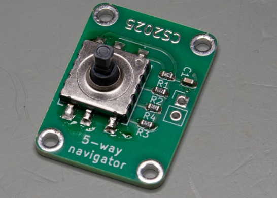
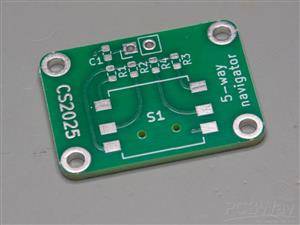
5-way navigator PCB
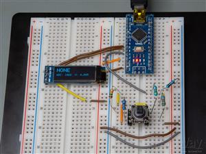
In this article, I show you a genius way of handling multiple buttons with a microcontroller. I “discovered” this method when I got my Hawkeye Firefly Split V6 PRO camera and used its remote controller. The remote controller has 5 buttons, but there are only two cables coming from it. This made me curious; therefore, I reverse-engineered the circuit and studied its working principles. Below, I will show you everything about the circuit, and I will explain how you can make your own circuit based on the principles I present.
In this remote, all buttons share a common ground return. One button - the DOWN button - connects the signal line directly to ground, bypassing all onboard resistors. The remaining four buttons each connect a dedicated resistor to ground when pressed:
- UP → 15 kΩ
- LEFT → 27 kΩ
- ENTER → 45.3 kΩ
- RIGHT → 6.8 kΩ
On the main board, the other wire from the remote connects to an ADC input via a pull-up resistor (presumably around 10 kΩ) tied to the supply rail (assume 5 V for this example). The second wire from the remote is tied to system ground.
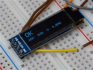
When no button is pressed, the ADC pin is pulled high to VCC through the pull-up, with the remote’s resistors effectively floating. Pressing one of the four resistor-equipped buttons completes a voltage divider between the pull-up resistor on the main board and the corresponding resistor in the remote, producing a distinct voltage at the ADC input. By reading this voltage, the firmware can determine which button was pressed.
The DOWN button is the exception: when pressed, it shorts the ADC pin directly to ground through zero ohms, producing a reading of (ideally) 0 V.
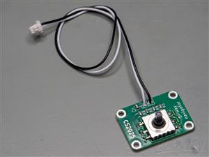
In summary, this design uses a resistor ladder to multiplex multiple button inputs into a single ADC channel, reducing the wiring requirement from six conductors to just two.
Of course, no circuit is without its limitations.
From the table above, it’s clear that the intended detection method is to identify a specific button press by measuring the corresponding voltage at the ADC input. For instance, if the ADC returns a code of approximately 414 (≈ 2.024 V), the firmware can infer that the RIGHT button is pressed.
However, this only holds true if the supply voltage is close to 5 V and the resistor values match their nominal specifications. The resistor tolerances can be addressed by using precision components -1 % or better. Supply voltage is less controllable, but with a quality USB power source, it will usually be close enough to 5 V. In addition, the firmware can implement an initial calibration routine to determine the actual ADC codes for each button at runtime, further compensating for component and supply variations.
Another potential complication arises if two buttons are pressed simultaneously - for example, moving the switch diagonally so that two resistors are connected to ground in parallel. This would produce an “invalid” ADC code that does not correspond to any single button, making identification ambiguous. Fortunately, in this particular design, the physical construction of the 5-way switch prevents true simultaneous actuation of two directional buttons. Even if it were possible, the application (navigating a camera menu) provides no meaningful scenario for pressing two buttons at once - pressing UP and LEFT simultaneously, or ENTER together with any other key, has no functional value. From both a mechanical and logical standpoint, it’s safe to assume that only one button will be pressed at a time.
Because high-precision resistors yield stable, repeatable voltage levels, the same method can be extended to support a greater number of inputs on a single ADC pin. By carefully selecting resistor values, multiple distinct voltage levels can be created, allowing many more buttons to be multiplexed onto one analogue input -provided the one-button-at-a-time assumption still holds.
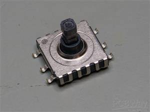
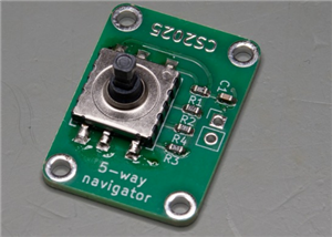
So, of course, I had to add my own twist to this circuit. To continue the elegance of having so few wires, I also reduced the number of components. Instead of five buttons, I used a MU-AS90R multidirectional switch in my circuit. This made it possible to halve the size of the original board while still having four mounting holes on it.
With this improvement, the circuit becomes easier to assemble and easier to use as well. The switch basically acts as a joystick; however, it does not have tilt angle-dependent values. It is just ON/OFF in a certain direction.
5-way navigator PCB
Project images are for reference only. Actual production is based on the manufacturing files on the project page.
Please review the designer's notes (e.g., PCB thickness) and select the appropriate options.
PCBWay is not responsible
for issues caused by unsuitable parameter selections.
For more important ordering information, please refer to
Read More


Raspberry Pi 5 7 Inch Touch Screen IPS 1024x600 HD LCD HDMI-compatible Display for RPI 4B 3B+ OPI 5 AIDA64 PC Secondary Screen(Without Speaker)
BUY NOW


- Comments(0)
- Likes(0)
 More by Curious Scientist
-
 USB PD Breadboard Power Supply
In this article, I show you my new creation. It is a USB PD decoy-based breadboard power supply. All...
USB PD Breadboard Power Supply
In this article, I show you my new creation. It is a USB PD decoy-based breadboard power supply. All...
-
 ADS1256 - RP2040 Custom DAQ Front Panel with GPIO
This is just a simple PCB panel that belongs to my other project which is a high-performance DAQ.A r...
ADS1256 - RP2040 Custom DAQ Front Panel with GPIO
This is just a simple PCB panel that belongs to my other project which is a high-performance DAQ.A r...
-
 ADS1256 - RP2040 Custom DAQ Front Panel without GPIO
This is just a simple PCB panel that belongs to my other project which is a high-performance DAQ.A r...
ADS1256 - RP2040 Custom DAQ Front Panel without GPIO
This is just a simple PCB panel that belongs to my other project which is a high-performance DAQ.A r...
-
 10th Anniversary Badge
I designed this small badge for PCBWay's 10th anniversary.I tried to make a deeper meaning to the bo...
10th Anniversary Badge
I designed this small badge for PCBWay's 10th anniversary.I tried to make a deeper meaning to the bo...
-
 ADS1256 - Atmega32u4 Custom DAQ board
IntroductionIn this project, I show you two things. One is a new version (v1.2) of my custom DAQ bas...
ADS1256 - Atmega32u4 Custom DAQ board
IntroductionIn this project, I show you two things. One is a new version (v1.2) of my custom DAQ bas...
-
 Debounced rotary encoder module
In this project, I show you my approach to making a rotary encoder module.One can buy different rota...
Debounced rotary encoder module
In this project, I show you my approach to making a rotary encoder module.One can buy different rota...
-
 Custom ADS1256 board with ATmega32U4
I created my own ADS1256 PCB after working with this AD converter for several years. I wanted to bui...
Custom ADS1256 board with ATmega32U4
I created my own ADS1256 PCB after working with this AD converter for several years. I wanted to bui...
-
 100 W USB PD Programmable Power Supply
In this article, I show you how I designed my own USB-PD (power delivery) programmable power supply ...
100 W USB PD Programmable Power Supply
In this article, I show you how I designed my own USB-PD (power delivery) programmable power supply ...
-
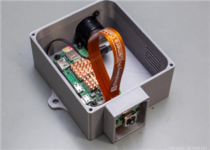 Raspberry Pi Zero 2W Bird Feeder Camera
In this article, I show you how I built my own Raspberry Pi Zero 2 W-based bird camera. The project ...
Raspberry Pi Zero 2W Bird Feeder Camera
In this article, I show you how I built my own Raspberry Pi Zero 2 W-based bird camera. The project ...
-
 CH32V003J4M6 - Miniature microcontroller board
I wanted something small but relatively capable, and since I have some experience with the CH32V003J...
CH32V003J4M6 - Miniature microcontroller board
I wanted something small but relatively capable, and since I have some experience with the CH32V003J...
-
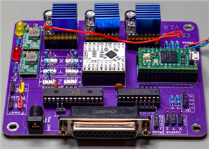 3-axis stepper motor controller with CNC pendant connectivity
In this article, I show you the updated version of my motorized microscope. In one of my older video...
3-axis stepper motor controller with CNC pendant connectivity
In this article, I show you the updated version of my motorized microscope. In one of my older video...
-
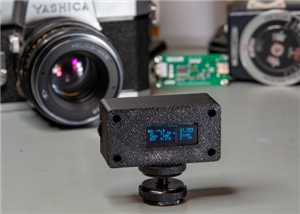 Light meter for analog cameras [CH32V006F8P6 + TSL2591]
In this article, I show you how I built my ow...
Light meter for analog cameras [CH32V006F8P6 + TSL2591]
Light meter for analog cameras [CH32V006F8P6 + TSL2591]In this article, I show you how I built my ow...
-
 5-way navigator PCB
In this article, I show you a genius way of handling multiple buttons with a microcontroller. I “dis...
5-way navigator PCB
In this article, I show you a genius way of handling multiple buttons with a microcontroller. I “dis...
-
 CH32V006K8U6 Development Board
IntroductionSo, I have been working with the CH32 microcontrollers and chips for a while, and I even...
CH32V006K8U6 Development Board
IntroductionSo, I have been working with the CH32 microcontrollers and chips for a while, and I even...
-
 PCBWay 11-year Anniversary Badge
This visual design was created by https://www.instagram.com/guiye.perez.bongiovanni/ ; however, only...
PCBWay 11-year Anniversary Badge
This visual design was created by https://www.instagram.com/guiye.perez.bongiovanni/ ; however, only...
-
 TCD1304 - STM32F401CCU6 breakout board
The recent modifications made to the circuit board design have improved its functionality and space ...
TCD1304 - STM32F401CCU6 breakout board
The recent modifications made to the circuit board design have improved its functionality and space ...
-
 TCD1304 miniature PCB rev2
The redesign of the PCB involved several key changes to improve its performance and decrease its siz...
TCD1304 miniature PCB rev2
The redesign of the PCB involved several key changes to improve its performance and decrease its siz...
-
 2-channel breadboard voltmeter
The project originally stems from my CH32 tutorial series. I started working with this chip not so l...
2-channel breadboard voltmeter
The project originally stems from my CH32 tutorial series. I started working with this chip not so l...
-
Programmable Mist Maker - XIAO / QT PY Extension
1150 2 1 -
RadioHAT - Raspberry Pi radio development platform
960 0 2 -
-
-
-
-
ARPS-2 – Arduino-Compatible Robot Project Shield for Arduino UNO
3382 0 6 -
A Compact Charging Breakout Board For Waveshare ESP32-C3
4001 3 8 -
AI-driven LoRa & LLM-enabled Kiosk & Food Delivery System
4389 2 2


